Transcription
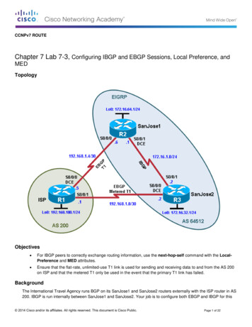
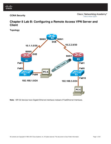
CCNPv7 ROUTEChapter 7 Lab 7-1, Configuring BGP with Default RoutingTopologyObjectives Configure BGP to exchange routing information with two ISPs.BackgroundThe International Travel Agency (ITA) relies extensively on the Internet for sales. For this reason, the ITA has decidedto create a multihomed ISP connectivity solution and contracted with two ISPs for Internet connectivity with faulttolerance. Because the ITA is connecting to two different service providers, you must configure BGP, which runsbetween the ITA boundary router and the two ISP routers.Note: This lab uses Cisco 1941 routers with Cisco IOS Release 15.4 with IP Base. The switches are Cisco WSC2960-24TT-L with Fast Ethernet interfaces, therefore the router will use routing metrics associated with a 100 Mb/s 2014 Cisco and/or its affiliates. All rights reserved. This document is Cisco Public.Page 1 of 11
CCNPv7 ROUTELab 7-1, Configuring BGP with Default Routinginterface. Depending on the router or switch model and Cisco IOS Software version, the commands available andoutput produced might vary from what is shown in this lab.Required Resources 3 routers (Cisco IOS Release 15.2 or comparable) Serial and Ethernet cablesStep 0: Suggested starting configurations.a. Apply the following configuration to each router along with the appropriate hostname. The exec-timeout 0 0command should only be used in a lab environment.Router(config)# no ip domain-lookupRouter(config)# line con 0Router(config-line)# logging synchronousRouter(config-line)# exec-timeout 0 0Step 1: Configure interface addresses.a. Using the addressing scheme in the diagram, create the loopback interfaces and apply IPv4 addresses to theseand the serial interfaces on ISP1 (R1), ISP2 (R3), and ITA (R2). The ISP loopbacks simulate real networks thatcan be reached through the ISP. The two loopbacks for the ITA router simulate the connections between the ITAboundary router and their core routers. Set a clock rate on the DCE serial interfaces.ISP1(config)# interface Lo0ISP1(config-if)# description ISP1 Internet NetworkISP1(config-if)# ip address 10.1.1.1 255.255.255.0ISP1(config-if)# exitISP1(config)# interface Serial0/0/0ISP1(config-if)# description ISP1 - ITAISP1(config-if)# ip address 10.0.0.1 255.255.255.252ISP1(config-if)# clock rate 128000ISP1(config-if)# no shutdownISP1(config-if)# endISP1#ITA(config)# interface Lo0ITA(config-if)# description Core router network link 1ITA(config-if)# ip address 192.168.0.1 255.255.255.0ITA(config)# exitITA(config-if)# interface Lo1ITA(config-if)# description Core router network link 2ITA(config-if)# ip address 192.168.1.1 255.255.255.0ITA(config-if)# exitITA(config)# interface Serial0/0/0ITA(config-if)# description ITA - ISP1ITA(config-if)# ip address 10.0.0.2 255.255.255.252ITA(config-if)# no shutdownITA(config-if)# exitITA(config)# interface Serial0/0/1ITA(config-if)# description ITA - ISP2ITA(config-if)# ip address 172.16.0.2 255.255.255.252 2014 Cisco and/or its affiliates. All rights reserved. This document is Cisco Public.Page 2 of 11
CCNPv7 ROUTELab 7-1, Configuring BGP with Default RoutingITA(config-if)# clock rate 128000ITA(config-if)# no shutdownITA(config-if)# endITA#ISP2(config)# interface Lo0ISP2(config-if)# description ISP2 Internet NetworkISP2(config-if)# ip address 172.16.1.1 255.255.255.0ISP2(config)# exitISP2(config-if)# interface Serial0/0/1ISP2(config-if)# description ISP2 - ITAISP2(config-if)# ip address 172.16.0.1 255.255.255.252ISP2(config-if)# no shutdownISP2(config-if)# endISP2#b. Use ping to test the connectivity between the directly connected routers. Note that router ISP1 cannot reachrouter ISP2.Step 2: Configure BGP on the ISP routers.On the ISP1 and ISP2 routers, configure BGP to peer with the ITA boundary router and advertise the ISP loopbacknetworks.ISP1(config)# router bgp 200ISP1(config-router)# neighbor 10.0.0.2 remote-as 100ISP1(config-router)# network 10.1.1.0 mask 255.255.255.0ISP2(config)# router bgp 300ISP2(config-router)# neighbor 172.16.0.2 remote-as 100ISP2(config-router)# network 172.16.1.0 mask 255.255.255.0Step 3: Configure BGP on the ITA boundary router.a. Configure the ITA router to run BGP with both Internet providers.ITA(config)# nfig-router)#ITA(config-router)#bgp 100neighbor 10.0.0.1 remote-as 200neighbor 172.16.0.1 remote-as 300network 192.168.0.0network 192.168.1.0You should see BGP neighbor peering messages on the console similar to the following.*Sep8 16:00:21.587: %BGP-5-ADJCHANGE: neighbor 10.0.0.1 Upb. To verify the configuration, check the ITA routing table with the show ip route command.ITA# show ip routeCodes: L - local, C - connected, S - static, R - RIP, M - mobile, B - BGPD - EIGRP, EX - EIGRP external, O - OSPF, IA - OSPF inter areaN1 - OSPF NSSA external type 1, N2 - OSPF NSSA external type 2E1 - OSPF external type 1, E2 - OSPF external type 2i - IS-IS, su - IS-IS summary, L1 - IS-IS level-1, L2 - IS-IS level-2ia - IS-IS inter area, * - candidate default, U - per-user static routeo - ODR, P - periodic downloaded static route, H - NHRP, l - LISPa - application route - replicated route, % - next hop override 2014 Cisco and/or its affiliates. All rights reserved. This document is Cisco Public.Page 3 of 11
CCNPv7 ROUTELab 7-1, Configuring BGP with Default RoutingGateway of last resort is not setCLBCLBCLCLITA#10.0.0.0/8 is variably subnetted, 3 subnets, 3 masks10.0.0.0/30 is directly connected, Serial0/0/010.0.0.2/32 is directly connected, Serial0/0/010.1.1.0/24 [20/0] via 10.0.0.1, 00:01:10172.16.0.0/16 is variably subnetted, 3 subnets, 3 masks172.16.0.0/30 is directly connected, Serial0/0/1172.16.0.2/32 is directly connected, Serial0/0/1172.16.1.0/24 [20/0] via 172.16.0.1, 00:00:53192.168.0.0/24 is variably subnetted, 2 subnets, 2 masks192.168.0.0/24 is directly connected, Loopback0192.168.0.1/32 is directly connected, Loopback0192.168.1.0/24 is variably subnetted, 2 subnets, 2 masks192.168.1.0/24 is directly connected, Loopback1192.168.1.1/32 is directly connected, Loopback1ITA has BGP routes to the loopback networks at each ISP router.c.Run the following Tcl script on all routers to verify connectivity If these pings are not successful, troubleshoot. Useexit to exit the Tcl script.Note: The WAN subnets connecting ITA (R2) to the ISPs (R1 and R3) are not advertised in BGP, so the ISPs willnot be able to ping each other’s serial interface address.ITA# tclshforeach address 6.1.1192.168.0.1192.168.1.1} {ping address }Step 4: Verify BGP on the routers.a. To verify the BGP operation on ITA, issue the show ip bgp command.ITA# show ip bgpBGP table version is 5, local router ID is 192.168.1.1Status codes: s suppressed, d damped, h history, * valid, best, i - internal,r RIB-failure, S Stale, m multipath, b backup-path, f RT-Filter,x best-external, a additional-path, c RIB-compressed,Origin codes: i - IGP, e - EGP, ? - incompleteRPKI validation codes: V valid, I invalid, N Not found* * * * 168.1.0Next Hop10.0.0.1172.16.0.10.0.0.00.0.0.0Metric LocPrf Weight Path00 200 i00 300 i032768 i032768 i 2014 Cisco and/or its affiliates. All rights reserved. This document is Cisco Public.Page 4 of 11
CCNPv7 ROUTELab 7-1, Configuring BGP with Default RoutingWhat is the local router ID?Which table version is displayed?An asterisk (*) next to a route indicates that it is valid. An angle bracket ( ) indicates that the route has beenselected as the best route.b. To verify the operation of ISP1, issue the show ip bgp command.ISP1# show ip bgpBGP table version is 5, local router ID is 10.1.1.1Status codes: s suppressed, d damped, h history, * valid, best, i - internal,r RIB-failure, S Stale, m multipath, b backup-path, f RT-Filter,x best-external, a additional-path, c RIB-compressed,Origin codes: i - IGP, e - EGP, ? - incompleteRPKI validation codes: V valid, I invalid, N Not foundNetwork* 10.1.1.0/24* 172.16.1.0/24* 192.168.0.0* 192.168.1.0ISP1#Next Hop0.0.0.010.0.0.210.0.0.210.0.0.2Metric LocPrf Weight Path032768 i0 100 300 i00 100 i00 100 iWhich table version is displayed and is it the same as the BGP table version for ITA?From ISP1, what is the path to network 172.16.1.0/24?c.On the ISP1 router, issue the shutdown command on Loopback0. Then on ITA, issue the show ip bgpcommand again.ISP1(config)# interface loopback 0ISP1(config-if)# shutdownISP1(config-if)#ITA# show ip bgpBGP table version is 6, local router ID is 192.168.1.1Status codes: s suppressed, d damped, h history, * valid, best, i - internal,r RIB-failure, S Stale, m multipath, b backup-path, f RT-Filter,x best-external, a additional-path, c RIB-compressed,Origin codes: i - IGP, e - EGP, ? - incompleteRPKI validation codes: V valid, I invalid, N Not foundNetwork* 172.16.1.0/24* 192.168.0.0* 192.168.1.0ITA#Next Hop172.16.0.10.0.0.00.0.0.0Metric LocPrf Weight Path00 300 i032768 i032768 iWhich table version is displayed? Why? 2014 Cisco and/or its affiliates. All rights reserved. This document is Cisco Public.Page 5 of 11
CCNPv7 ROUTELab 7-1, Configuring BGP with Default RoutingWhat happened to the route for network 10.1.1.0/24?d. Bring ISP1 router Loopback0 back up by issuing the no shutdown command.ISP1(config)# interface loopback 0ISP1(config-if)# no shutdownISP1(config-if)#e. On ITA, issue the show ip bgp neighbors command. The following is a partial sample output of the commandshowing neighbor 172.16.0.1.ITA# show ip bgp neighborsBGP neighbor is 10.0.0.1, remote AS 200, external linkBGP version 4, remote router ID 10.1.1.1BGP state Established, up for 00:20:47Last read 00:00:49, last write 00:00:41, hold time is 180, keepalive interval is60 secondsNeighbor sessions:1 active, is not multisession capable (disabled)Neighbor capabilities:Route refresh: advertised and received(new)Four-octets ASN Capability: advertised and receivedAddress family IPv4 Unicast: advertised and receivedEnhanced Refresh Capability: advertised and receivedMultisession Capability:Stateful switchover support enabled: NO for session 1Message statistics:InQ depth is 0OutQ depth is ves:1517Route Refresh:00Total:2119Default minimum time between advertisement runs is 30 seconds output omitted Based on the output of this command, what is the BGP state between this router and ISP2?How long has this connection been up?Step 5: Configure route filters.a. Check the ISP2 routing table using the show ip route command. ISP2 should have a route that belongs to ISP1,network 10.1.1.0.ISP2# show ip route output omitted 2014 Cisco and/or its affiliates. All rights reserved. This document is Cisco Public.Page 6 of 11
CCNPv7 ROUTEBCLCLBBISP2#Lab 7-1, Configuring BGP with Default Routing10.0.0.0/24 is subnetted, 1 subnets10.1.1.0 [20/0] via 172.16.0.2, 00:09:26172.16.0.0/16 is variably subnetted, 4 subnets, 3 masks172.16.0.0/30 is directly connected, Serial0/0/1172.16.0.1/32 is directly connected, Serial0/0/1172.16.1.0/24 is directly connected, Loopback0172.16.1.1/32 is directly connected, Loopback0192.168.0.0/24 [20/0] via 172.16.0.2, 00:28:05192.168.1.0/24 [20/0] via 172.16.0.2, 00:28:05If ITA advertises a route belonging to ISP1, ISP2 installs that route in its table. ISP2 might then attempt to routetransit traffic through the ITA. This would make ITA a transit router. A traceroute to ISP1’s Lo0 interface illustratesthis issue.ISP2# traceroute 10.1.1.1Type escape sequence to abort.Tracing the route to 10.1.1.1VRF info: (vrf in name/id, vrf out name/id)1 172.16.0.2 8 msec 4 msec 8 msec2 * * *3 * * *4 * * * control-shift-6 to break ISP2#The traceroute 10.1.1.1 fails because ISP1 does not have a route to the source IPv4 address of the traceroute,172.16.0.1. It is common in BGP networks not to advertise the links between providers in BGP. A traceroute usingthe source IPv4 address of ISP2’ Lo0 interface is successful, showing that ITA is a transit router for this network.ISP2# traceroute 10.1.1.1 source loopback0Type escape sequence to abort.Tracing the route to 10.1.1.1VRF info: (vrf in name/id, vrf out name/id)1 172.16.0.2 8 msec 4 msec 8 msec2 10.0.0.1 12 msec * 12 msecISP2#b. Configure the ITA router so that it advertises only ITA networks 192.168.0.0 and 192.168.1.0 to both providers.On the ITA router, configure the following access list.ITA(config)# access-list 1 permit 192.168.0.0 0.0.1.255c.Apply this access list as a route filter using the distribute-list keyword with the BGP neighbor statement.ITA(config)# router bgp 100ITA(config-router)# neighbor 10.0.0.1 distribute-list 1 outITA(config-router)# neighbor 172.16.0.1 distribute-list 1 outd. Check the routing table for ISP2 again. The route to 10.1.1.0, ISP1, should still be in the table.ISP2# show ip route output omitted BC10.0.0.0/24 is subnetted, 1 subnets10.1.1.0 [20/0] via 172.16.0.2, 00:25:14172.16.0.0/16 is variably subnetted, 4 subnets, 3 masks172.16.0.0/30 is directly connected, Serial0/0/1 2014 Cisco and/or its affiliates. All rights reserved. This document is Cisco Public.Page 7 of 11
CCNPv7 ROUTELab 7-1, Configuring BGP with Default RoutingL172.16.0.1/32 is directly connected, Serial0/0/1C172.16.1.0/24 is directly connected, Loopback0L172.16.1.1/32 is directly connected, Loopback0B192.168.0.0/24 [20/0] via 172.16.0.2, 00:43:53B192.168.1.0/24 [20/0] via 172.16.0.2, 00:43:53ISP2#e. Return to ITA and issue the clear ip bgp * command. Wait until the routers reach the established state, whichmight take several seconds, and then recheck the ISP2 routing table. The route to ISP1, network 10.1.1.0, shouldno longer be in the routing table for ISP2, and the route to ISP2, network 172.16.1.0, should not be in the routingtable for ISP1.ITA# clear ip bgp *ITA#*Sep 8 16:47:25.179: %BGP-5-ADJCHANGE: neighbor 10.0.0.1 Down User reset*Sep 8 16:47:25.179: %BGP SESSION-5-ADJCHANGE: neighbor 10.0.0.1 IPv4 Unicasttopology
CCNPv7 ROUTE Chapter 7 Lab 7-1, Configuring BGP with Default Routing Topology Objectives Configure BGP to exchange routing information with two ISPs. Background The International Travel Agency (ITA) relies extensively on the Internet for sales. For this reason, the ITA has decided to create a multihomed ISP connectivity solution and contracted with two ISPs for Internet connectivity with fault .