Transcription
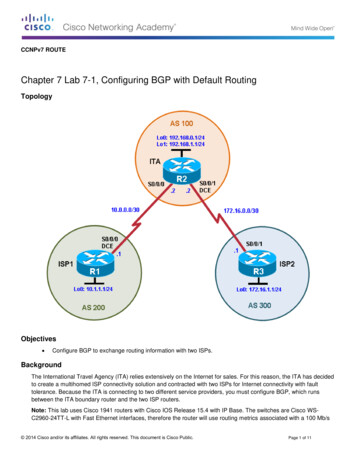
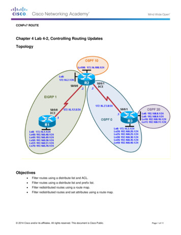
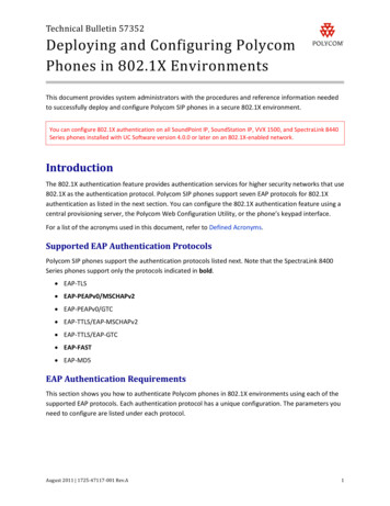
CCNA SecurityChapter 8 Lab B: Configuring a Remote Access VPN Server andClientTopologyNote: ISR G2 devices have Gigabit Ethernet interfaces instead of FastEthernet Interfaces.All contents are Copyright 1992–2012 Cisco Systems, Inc. All rights reserved. This document is Cisco Public Information.Page 1 of 24
CCNA SecurityIP Addressing TableDeviceR1R2R3InterfaceFa0/1IP Address192.168.1.1Subnet Mask255.255.255.0Default GatewayN/ASwitch PortS1 Fa0/5S0/0/0 5.255.255.252N/AN/AS0/0/1 255.255.255.0N/AS3 .168.1.3255.255.255.0192.168.1.1S1 Fa0/6PC-CNIC192.168.3.3255.255.255.0192.168.3.1S3 Fa0/18ObjectivesPart 1: Basic Router Configuration Configure host names, interface IP addresses, and access passwords. Configure static routing.Part 2: Configuring a Remote Access VPN Configure a zone-based firewall (ZBF) on R3 using CCP. Configure Router R3 to support Cisco Easy VPN Server using CCP. Configure the Cisco VPN Client on PC-A and connect to R3. Verify the configuration. Test VPN functionality.BackgroundVPNs can provide a secure method of transmitting data over a public network, such as the Internet. Acommon VPN implementation is used for remote access to a corporate office from a telecommuter locationsuch as a small office or home office (SOHO).In this lab, you build a multi-router network and configure the routers and hosts. You configure a remoteaccess IPsec VPN between a client computer and a simulated corporate network. You start by using CCP toconfigure a zoned-based firewall (ZBF) to prevent connections from outside the corporate network. You nextuse CCP to configure Cisco Easy VPN Server on the corporate gateway router. Finally, you configure theCisco VPN Client on a host and connect to the corporate network through a simulated ISP router.The Cisco VPN Client allows organizations to establish end-to-end, encrypted (IPsec) VPN tunnels for secureconnectivity for mobile employees or teleworkers. It supports Cisco Easy VPN, which allows the client toreceive security policies upon a VPN tunnel connection from the central site VPN device (Cisco Easy VPNServer), minimizing configuration requirements at the remote location. Easy VPN is a scalable solution forremote access deployments for which it is impractical to individually configure policies for multiple remotePCs.Router R1 represents a remote site, and R3 represents the corporate headquarters. Host PC-A simulates anemployee connecting from home or a small office over the Internet. Router R2 simulates an Internet ISProuter and acts as a passthrough with no knowledge of the VPN connection running through it.Note: The router commands and output in this lab are from a Cisco 1841 with Cisco IOS Release 12.4(20)T(Advanced IP image). Other routers and Cisco IOS versions can be used. See the Router Interface Summarytable at the end of the lab to determine which interface identifiers to use based on the equipment in the lab.All contents are Copyright 1992–2012 Cisco Systems, Inc. All rights reserved. This document is Cisco Public Information.Page 2 of 24
CCNA SecurityDepending on the router model and Cisco IOS version, the commands available and the output producedmight vary from what is shown in this lab.Note: Make sure that the routers and the switches have been erased and have no startup configurations.Required Resources 3 routers with Cisco 1841 with Cisco IOS Release 12.4(20)T1 or comparable 2 switches (Cisco 2960 or comparable) PC-A: Windows XP, Vista, or Windows 7 with Cisco VPN Client PC-C: Windows XP, Vista, or Windows 7 with CCP 2.5 installed Serial and Ethernet cables as shown in the topology Rollover cables to configure the routers via the consoleCCP Notes: Refer to Chp 00 Lab A for instructions on how to install CCP. Hardware/software recommendationsfor CCP include Windows XP, Vista, or Windows 7 with Java version 1.6.0 11 up to 1.6.0 21,Internet Explorer 6.0 or above and Flash Player Version 10.0.12.36 and later. If the PC on which CCP is installed is running Windows Vista or Windows 7, it may be necessary toright-click on the CCP icon or menu item, and choose Run as administrator. In order to run CCP, it may be necessary to temporarily disable antivirus programs and O/S firewalls.Make sure that all pop-up blockers are turned off in the browser.All contents are Copyright 1992–2012 Cisco Systems, Inc. All rights reserved. This document is Cisco Public Information.Page 3 of 24
CCNA SecurityPart 1: Basic Router ConfigurationIn Part 1, you set up the network topology and configure basic settings, such as the interface IP addressesand static routing. Perform the steps on the routers as indicated.Step 1: Cable the network as shown in the topology.Attach the devices shown in the topology diagram, and cable as necessary.Step 2: Configure basic settings for all routers.a. Configure host names as shown in the topology.b. Configure the physical interface IP addresses as shown in the IP addressing table.c.Configure a clock rate for the routers with a DCE serial cable attached to their serial interface.R1(config)# interface S0/0/0R1(config-if)# clock rate 64000d. Disable DNS lookup to prevent the router from attempting to translate incorrectly entered commandsas though they were host names.R1(config)# no ip domain-lookupStep 3: Configure static default routes on R1 and R3.Configure a static default route from R1 to R2 and from R3 to R2.R1(config)# ip route 0.0.0.0 0.0.0.0 10.1.1.2R3(config)# ip route 0.0.0.0 0.0.0.0 10.2.2.2Step 4: Configure static routes on R2.a. Configure a static route from R2 to the R1 LAN.R2(config)# ip route 192.168.1.0 255.255.255.0 10.1.1.1b. Configure a static route from R2 to the R3 LAN.R2(config)# ip route 192.168.3.0 255.255.255.0 10.2.2.1Step 5: Configure PC host IP settings.Configure a static IP address, subnet mask, and default gateway for PC-A and PC-C, as shown in the IPaddressing table.Step 6: Verify connectivity between PC-A and R3.From PC-A, ping the R3 S0/0/1 interface at IP address 10.2.2.1.PC-A:\ ping 10.2.2.1Are the results successful?If the pings are not successful, troubleshoot the basic device configurations before continuing.Step 7: Configure a minimum password length.Note: Passwords in this lab are set to a minimum of 10 characters, but are relatively simple for the benefitof performing the lab. More complex passwords are recommended in a production network.Use the security passwords command to set a minimum password length of 10 characters.R1(config)# security passwords min-length 10All contents are Copyright 1992–2012 Cisco Systems, Inc. All rights reserved. This document is Cisco Public Information.Page 4 of 24
CCNA SecurityStep 8: Configure the enable secret password and console and vty lines.a. Configure the enable secret password cisco12345 on R1.R1(config)# enable secret cisco12345b. Configure a console password and enable login for router R1. For additional security, the exectimeout command causes the line to log out after 5 minutes of inactivity. The loggingsynchronous command prevents console messages from interrupting command entry.Note: To avoid repetitive logins during this lab, the exec-timeout can be set to 0 0, which prevents itfrom expiring. However, this is not considered a good security practice.R1(config)# )#R1(config-line)#c.console 0password ciscoconpassexec-timeout 5 0loginlogging synchronousConfigure the password on the vty lines for router R1.R1(config)# )#vty 0 4password ciscovtypassexec-timeout 5 0logind. Repeat these configurations on R2 and R3.Step 9: Encrypt clear text passwords.a. Use the service password-encryption command to encrypt the console, aux, and vtypasswords.R1(config)# service password-encryptionb. Issue the show run command. Can you read the console, aux, and vty passwords? Why or whynot?c.Repeat this configuration on R2 and R3.Step 10: Configure a login warning banner on routers R1 and R3.Configure a message-of-the-day (MOTD) warning banner to unauthorized users.R1(config)# banner motd Unauthorized access strictly prohibited andprosecuted to the full extent of the law Step 11: Save the basic running configuration for all three routers.Save the running configuration to the startup configuration from the privileged EXEC prompt.R1# copy running-config startup-configPart 2: Configuring a Remote Access VPNIn Part 2 of this lab, configure a firewall and a remote access IPsec VPN. You will use CCP to configure R3 asa VPN server. On PC-C you will enable and configure the Cisco VPN client.Task 1: Prepare R3 for CCP AccessStep 1: Configure HTTP router access and a AAA user.a. Enable the HTTP server on R3.All contents are Copyright 1992–2012 Cisco Systems, Inc. All rights reserved. This document is Cisco Public Information.Page 5 of 24
CCNA SecurityR3(config)# ip http serverNote: For added security, you can enable the HTTP secure server on R3 using the ip http secureserver command. The HTTP server and the HTTP secure server are disabled by default.b. Create an admin01 account on R3 with privilege level 15 and a password of admin01pass for usewith AAA.R3(config)# username admin01 privilege 15 password 0 admin01passc.Configure R3 so that CCP use the local database to authenticate web sessions.R3(config)# ip http authentication localStep 2: Access CCP and discover R3.a. Run the CCP application on PC-C. In the Select/Manage Community window, input the R1 IPaddress 192.168.3.1 in the Hostname/Address field, admin01 in the Username field andadmin01pass in the Password field. Click on the OK button.b. At the CCP Dashboard, click the Discovery button to discover and connect to R3. If the discoveryprocess fails, click the Discover Details button to determine the problem in order to resolve theissue.All contents are Copyright 1992–2012 Cisco Systems, Inc. All rights reserved. This document is Cisco Public Information.Page 6 of 24
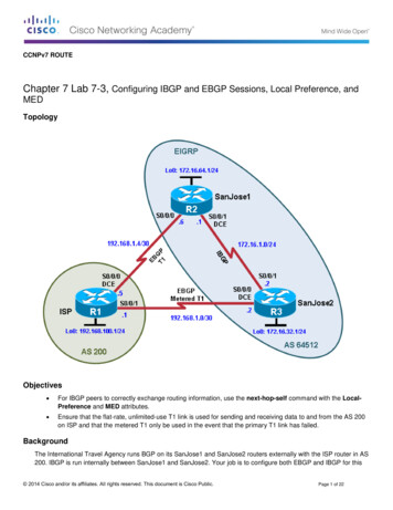
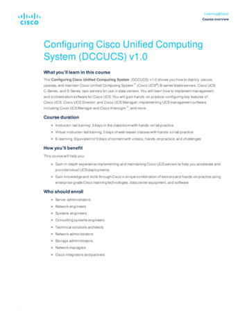
CCNA SecurityTask 2: Configure a ZBF Firewall on R3Step 1: Use the CCP firewall wizard to configure a zone-based firewall (ZBF) on R3.a. Click the Configure button at the top of the CCP screen, and choose Security Firewall Firewall.b. Choose Basic Firewall and click the Launch the selected task button. On the Basic FirewallConfiguration wizard screen, click Next.c.Check the Inside (Trusted) check box for FastEthernet0/1 and the Outside (Untrusted) check boxfor Serial0/0/1. Click Next. Click OK when the CCP launch warning for Serial0/0/1 is displayed.All contents are Copyright 1992–2012 Cisco Systems, Inc. All rights reserved. This document is Cisco Public Information.Page 7 of 24
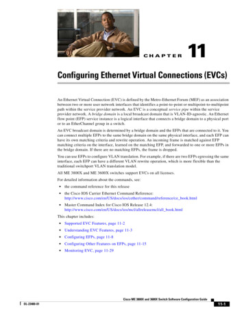
CCNA Securityd. In the next window, select Low Security for the security level and click Next.e. In the Summary window, click Finish.f.Click Deliver to send the commands to the router. Click OK in the Commands Delivery Statuswindow. Click OK on the Information window. You are returned to the Edit Firewall Policy tab asshown below.Step 2: Verify firewall functionality.a. From PC-C, ping the R2 interface S0/0/1 at IP address 10.2.2.2.All contents are Copyright 1992–2012 Cisco Systems, Inc. All rights reserved. This document is Cisco Public Information.Page 8 of 24
CCNA SecurityAre the pings successful? Why or why not?b. From external router R2, ping PC-C at IP address 192.168.3.3Are the pings successful? Why or why not?Task 3: Use the CCP VPN Wizard to Configure the Easy VPN ServerStep 1: Launch the Easy VPN Server wizard and configure AAA services.a. Click the Configure button at the top of the CCP home screen. Choose Security VPN Easy VPNServer.b. Click on the Launch Easy VPN Server Wizard button.c.The Easy VPN Server wizard checks the router configuration to see if AAA is enabled. If AAA is notenabled, the Enable AAA window displays. AAA must be enabled on the router before the Easy VPNServer configuration starts. Click Yes to continue with the configuration.d. When prompted to deliver the configuration to the router, click Deliver.e. In the Command Delivery Status window, click OK. When the message “AAA has been successfullyenabled on the router” displays, click OK.f.When returned to the Easy VPN Server wizard window, click Next.g. Now that AAA is enabled, you can start the Easy VPN Server wizard by clicking the Launch EasyVPN Server Wizard button. Read through the descriptions of the tasks that the wizard guides youthrough.All contents are Copyright 1992–2012 Cisco Systems, Inc. All rights reserved. This document is Cisco Public Information.Page 9 of 24
CCNA SecurityHow does the client receive the IPsec policies?How does the Easy VPN remote server configuration differ from the site-to-site?h. Click Next when you are finished answering the above questions.Step 2: Configure the virtual tunnel interface and authentication.a. Select the interface on which the client connections terminate. Click the Unnumbered to radio buttonand select the Serial0/0/1 interface from the pull-down menu.b. Choose Pre-shared Keys for the authentication type and click Next to continue.All contents are Copyright 1992–2012 Cisco Systems, Inc. All rights reserved. This document is Cisco Public Information.Page 10 of 24
CCNA SecurityStep 3: Select an IKE proposal.a. In the IKE Proposals window, the default IKE proposal is used for R3.What is the encryption method used with the default IKE policy?What is the hash algorithm used to ensure that the keys have not been tampered with?b. Click Next to accept the default IKE policy.Note: Configurations on both sides of the tunnel must match exactly. The Cisco VPN client automaticallyselects the proper configuration for itself. Therefore, an IKE configuration is not necessary on the clientPC.Step 4: Select the transform set.a. In the Transform Set window, the default CCP transform set is used. What ESP encryption method isused with the default transform set?All contents are Copyright 1992–2012 Cisco Systems, Inc. All rights reserved. This document is Cisco Public Information.Page 11 of 24
CCNA Securityb. Click Next to accept the default transform set.Step 5: Specify group authorization and group policy lookup.a. In the Group Authorization and Group Policy Lookup window, choose the Local option.b. Click Next to create a new AAA method list for group policy lookup that uses the local routerdatabase.All contents are Copyright 1992–2012 Cisco Systems, Inc. All rights reserved. This document is Cisco Public Information.Page 12 of 24
CCNA SecurityStep 6: Configure user authentication (XAuth).a. In the User Authentication (XAuth) window, you can select where user credentials will be configured.You can select an external server, such as a RADIUS server, a local database, or both. Check theEnable User Authentication check box and accept the default of Local Only.Where does the router look for valid user accounts and passwords to authenticate remote VPN userswhen they attempt to log in?b. Click the Add User Credentials button. In the User Accounts window, you can view currently definedusers or add new users.What is the name of the user currently defined and what is the user privilege level?How was this user defined?c.In the User Accounts window, click the Add button to add another user. Enter the usernameVPNuser1 with a password of VPNuser1pass. Select the check box for encrypting the passwordusing the MD5 hash algorithm. Leave the privilege level at 1.What is the range of privilege level that can be set for a user?All contents are Copyright 1992–2012 Cisco Systems, Inc. All rights reserved. This document is Cisco Public Information.Page 13 of 24
CCNA Securityc.Click OK to accept the VPNuser1 entries, and then click OK to close the User Accounts window.d. In the User Authentication (XAuth) window, click Next to continue.All contents are Copyright 1992–2012 Cisco Systems, Inc. All rights reserved. This document is Cisco Public Information.Page 14 of 24
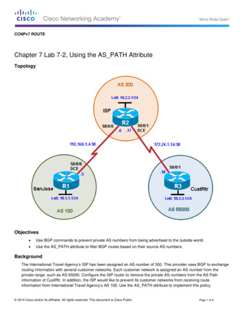
CCNA SecurityStep 7: Specify group authorization and user group policies.a. In the Group Authorization and User Group Policies window, you must create at least one grouppolicy for the VPN server.b. Click Add to create a group policy.c.In the Add Group Policy window, enter VPN-Access as the name of this group. Enter a new preshared key of cisco12345 and then re-enter it.d. Leave the Pool Information box checked and enter a starting address of 192.168.3.100, an endingaddress of 192.168.3.150, and a subnet mask of 255.255.255.0.e. Enter 50 for the Maximum Connections Allowed.f.Click OK to accept the entries.All contents are Copyright 1992–2012 Cisco Systems, Inc. All rights reserved. This document is Cisco Public Information.Page 15 of 24
CCNA Securityg. A CCP warning message displays indicating that the IP addresses in the pool and the IP address ofthe Fast Ethernet0/1 interface are in the same subnet. Click Yes to continue.h. When you return to the Group Authorization window, check the Configure Idle Timer check box andenter one hour (1). This disconnects idle users if there is no activity for one hour and allows others toconnect. Click Next to continue.i.When the Cisco Tunneling Control Protocol (cTCP) window displays, do not enable cTCP. Click Nextto continue.All contents are Copyright 1992–2012 Cisco Systems, Inc. All rights reserved. This document is Cisco Public Information.Page 16 of 24
CCNA Securityj.When the Easy VPN Server Passthrough Configuration window displays, make sure that the ActionModify check box is checked. This option allows CCP to modify the firewall on S0/0/1 to allow IPsecVPN traffic to reach the internal LAN. Click OK to continue.All contents are Copyright 1992–2012 Cisco Systems, Inc. All rights reserved. This document is Cisco Public Information.Page 17 of 24
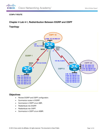
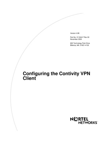
CCNA SecurityStep 8: Review the configuration summary and deliver the commands.a. Scroll through the commands that CCP will send to the router. Do not check the check box to test theVPN. Click Finish.b. When prompted to deliver the configuration to the router, click Deliver.c.In the Command Delivery Status window, click OK. How many commands are delivered?Step 9: Test the VPN Server.a. You are returned to the main VPN window with the Edit Easy VPN Server tab selected. Click theTest VPN Server button in the lower right corner of the screen.b. In the VPN Troubleshooting window, click the Start button.Your screen should look similar to the one below. Click OK to close the information window. Click Closeto exit the VPN Troubleshooting window.All contents are Copyright 1992–2012 Cisco Systems, Inc. All rights reserved. This document is Cisco Public Information.Page 18 of 24
CCNA SecurityNote: If you receive a failure after testing the VPN server, close the VPN Troubleshooting window.1. Click the Edit button on top right of Edit Easy VPN Server Tab.2. Click OK in the Edit Easy VPN Server Connection window.3. Click OK in the Easy VPN Server Passthrough Configuration window.4. Check the box to the right of the FastEthernet0/1 interface indicating that it is inside (Trusted).5. Rerun Test VPN Server by clicking on that button on bottom right of Edit Easy VPN Server Tab.6. Click Start button and test should pass this time.Task 4: Use the Cisco VPN Client to Test the Remote Access VPNStep 1: (Optional) Install the Cisco VPN client.If the Cisco VPN Client software on host PC-A is not installed, install it now. If you do not have the Cisco VPNClient software, contact your instructor.All contents are Copyright 1992–2012 Cisco Systems, Inc. All rights reserved. This document is Cisco Public Information.Page 19 of 24
CCNA SecurityStep 2: Configure PC-A as a VPN client to access the R1 VPN server.a. Start the Cisco VPN Client and choose Connection Entries New, or click the New icon with thered plus sign (
Cisco VPN Client on a host and connect to the corporate network through a simulated ISP router. The Cisco VPN Client allows organizations to establish end-to-end, encrypted (IPsec) VPN tunnels for secure connectivity for mobile employees or teleworkers. It supports