Transcription
Selectable Resolution LVDT Probes and DisplaysSENSOR SYSTEMSMu-CheckerBulletin No. 2215(3)
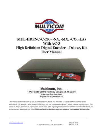
Mitutoyo Selectable Resolution LVDT ProbeDemands Suited to a Wide Application RanBuilding into a Production Line!A low-measuring-force sensor enables even a soft workpieceto be measured without significant deformation.Standard type measuring force: 0.2N (No. 519-521)Low-force type measuring force: 0.02N (No. 519-522)Compact models are best suited for in-line use.No. 519-346No. 519-347Analog and digital indicator units are both equippedwith a Zero-setting function.No. 519-552A2No. 519-562A
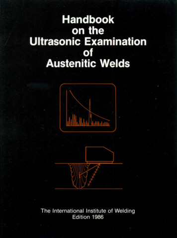
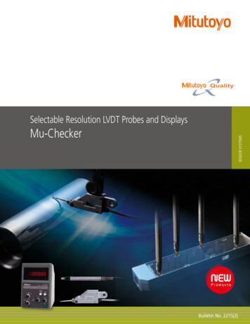
es and Displays Adaptable to Customernge from the Inspection Room toMeasurement PrincipleMoving iron orunitThis instrument uses a differentialinductance displacement sensor energizedby a 5kHz AC exciting voltage appliedacross two identical series-connected coils,L1 and L2. An iron core connected to thestylus moves close to both cores and variesthe impedance of each coil depending onits position, and the voltage at the junctionbetween the coils varies as the impedancedifference. Two resistors, R1 and R2, forma bridge circuit with the coils and thebridge output voltage drives electronicamplification and conditioning circuits toprovide a voltage signal proportional todisplacement of the stylus.Mu-checker Block atorcircuitAmplifierAnalog indicatorA/DconverterPower supply g output(to a recorder, etc.)Digital outputBCD outputRS-232C outputDigital indicator3
ApplicationsMeasuring runoutMeasuring the inclination of a pinThe distortion of a core is measured with lever head No.519-522 and Mu-checker No. 519-552A.The inclination of a capstan pin is measured with cartridgehead No. 519-385 and digital Mu-checker No. 519-562A.Pin inclination measurement (X-axis direction)(Max - Min) measurement(Max - Min) measurementPin inclination measurement (Y-axis direction)Measuring the thickness of rolled sheetMeasuring the maximum runout of a gearThe thickness of a rolled sheet material is measured withlever head No. 519-521 and Mu-checker counter EV-16A.The maximum runout of a gear is measured with lever headNo. 519-521 and Mu-checker counter EV-16A.振れ測定Multipoint measurement/judgment振れ測定Maximum value measurementMeasuring straightness of sheet metalMultipoint measurement on a VTR chassisThe straightness of a component is measured with cartridge厚さ測定head No. 519-385 and Mu-checker No. 519-552A.A VTR chassis is measured at multiple points with cartridgehead No. 519-385 and Mu-checker counter EV-16A.Note: A measuring fixture isolates thegage from the component to avoidsliding wear on the gage contact point asthe component is moved as shown.最大値測定Straightness measurementMultipoint measurement/judgment4
Measuring the pitch of HDD head componentsMeasuring the concentricity of a shaftThe pitch of HDD detector head components is measured withlever head No. 519-521 and Mu-checker counter EV-16A.The concentricity and runout of a shaft are measured withcartridge head No. 519-385 and Mu-checker counterEV-16A.Note: Measuring fixtures isolate the gagesfrom the component to avoid sliding wearon the gage contact points as thecomponent is rotated.Multipoint measurement/judgmentMultipoint measurement/judgmentMeasuring the inside width of a wheelMeasuring the height of a piston headThe inside width of a car wheel is measured with lever headNo. 519-521 and digital Mu-checker No. 519-562A.The height of a piston head is measured with cartridge headNo. 519-385 and Mu-checker counter EV-16A.Inside widthmeasurementMultipoint measurement/judgmentMeasuring the pitch and runout of slitter bladesMeasuring the warp on an LCD panelThe pitch and runout of slitter blades are measured with leverhead No. 519-521 and Mu-checker counter EV-16A.The warp of an LCD panel is measured with lever head No.519-522 and Mu-checker No. 519-552A. This lever headwith a low measuring force allows measurement withoutscratching the workpiece.振れ測定/判定Multipoint measurement/judgmentHeight measurement5
Mu-Checker System DiagramLever HeadNo. 519-327 0.5mmP8Lever HeadNo. 519-521 0.5mmP8Standard typeMu-CheckerNo. 519-552ALever HeadNo. 519-522 0.5mmP8Lever HeadNo. 519-326 0.5mmP8Cartridge HeadNo. 519-331No. 519-332 0.5mmP10P14Differential typeMu-CheckerNo. 519-554A P14Cartridge HeadNo. 519-346 0.25mmP10Cartridge HeadNo. 519-347 0.5mmCartridge HeadNo. 519-385 1.5mmCartridge HeadNo. 519-341 2.5mmCartridge HeadNo. 519-348 1.0mm6P10Digital differential typeMu-CheckerNo. 519-562A(with Digimatic output) P15P10P10P10Mu-checker PC interfaceEV-16ANo. 519-355 P16
Analog signalDigimatic signalPersonal Computer(separately required)Programmable Controller(sold separately)Digimatic Mini-ProcessorDP-1VR No. 264-504-5ADisplay unit D-EVNo. 02ADD400Analog Recorder(sold separately)7
ProbesLever Head TypeThis type allows multipoint measurement of small parts, flatness and straightness measurement on an X/Y table, etc. and runout measurement of shafts.SpecificationsMeasuring range Stylus stroke[mm][mm]External dimensions[mm]5417φ6.6No. 519-521(27.75)1.75φ6.5 φ14352621.3199.2147Order No.24.930.75.8135417φ6.6No. 519-522(27.75)1.75φ6.5 φ14352621.39.2 1914752.324.930.7 0.5 0.6 0.5 0.655.81352.3131443ø6.56.5 9 74.5ø2R7268No. 519-32622.5 5.567.61356No. 519-32724ø6.57R7824732.36.5 15.83.51625.3
Note on stylus angleMeasuringforceLinearity[%]Approx.0.2NBearing unitstructurePivot bearing typeIf the stylus of a pivot bearing type probe (No. 519-521, No. 519-522, orNo. 519-327) makes an angle with a workpiece surface, as in the figure,calibration should be performed for accurate measurement. Alternatively,the displayed value may be corrected by multiplying it by the appropriatecorrection factor as given in the table.Remarks/Interchangeable stylusAngleCorrection factor0 1.0010 0.9820 0.9430 0.8740 0.77θ50 0.6460 0.50Display value Correction factor Corrected valueMeasuring directionchanged with the forwardreverse leverNo. 520940 (ø1)No. 520939 (ø2)No. 520938 (ø3)60 15Dimensions of Dovetail Plateon probe body(5.934)1.5 0.3Transfer Standø30ø880Stem mounting holewithout Bush ø9.53with Bush ø8AnvilFlatness of 1.3 µm or lessø58160(W) 100(D)21545Order No.519-109-10Mounting hole[mm]ø9.53, ø8 with BushEffective transfer range Fine adjustment range[mm][mm]0-3201Lever Head Mounting Brackets (Option)クランプClampStemø18ø610.9 0.3168Major Specifications6Approx.0.15NThe measuring force isadjustable with the upperdial.No need for displayed valuecorrection when stylus makesParallel leaf spring an angle with surfacetypeNo. 102824 (ø1)No. 102832 (ø2)No. 102826 (ø3)Note: Only the ø2 stylus tipis a standard accessory.12.2ø4 dovetail-grooved stem ø6 dovetail-grooved stem Clamp for ø6/ø8 dovetailNo. 902802No. 902803grooved stemø6No. 9020535.8No need for change ofmeasuring direction due tono-clutch typeApprox.0.15N 0.5Pivot bearing type No. 102824 (ø1)No. 102832 (ø2)No. 102826 (ø3)Note: Only the ø2 stylus tipis a standard accessory.65No. 519-109-10(with a serrated anvil)5945平面度1μm以下4303851644ø58 焼入鋼6354060Pivot bearing type No. 520940 (ø1)No. 520939 (ø2)No. 520938 (ø3)430Approx.0.02Nø308050Low measuring force16.227.5ø8No. 902053ø8 dovetail-grooved stem ø9.5 dovetail-grooved stem Clamp for o6/o9.5 dovetail-grooved stemNo. 900320No. 902804No. 902805Holder 扌ø6扌ø6扌 扌Holder arm A (square 9 9 100)No. 900209.25” x .5"Holder arm B (ø8 115)No. 900211953639 (Length: 2")900306 (Length: 4")9
Cartridge Head TypeA cartridge head type is easily built-in to the equipment due to its slim and compact shape.This type of sensor is optimal for an automatic measuring machine.SpecificationsOrder No.8.1 (0-point position)1.3R1.5715 154.5 0.57.3ø120ø8h6 -0.009No. 519-331No. 519-332Measuringrange [mm]External dimensions [mm]* for 519-332: (ø) .375" stem, 4-48UNF contact point25123.5 (0-point position)0.26No. 519-3460.34 0.250.85R1.5No. 519-3476.8 (0-point position)21.65 (0-point position)1.65SR 0.522.534.5112.358312.35 1.51.50φ8h6 -0.009No. 519-385ø3.50ø8h6 -0.0090.650ø8h6 -0.009.25R1No. 519-341R1.5 2.52714.5815.25 (0-point position)No. 519-3484831 2.5R1.51.15ø8h60-0.00914.75 (0-point position)0ø8h6 -0.0092.83.21.35Common SpecificationsConnection �———————— Half-bridge typeExciting 3.0VRMSExciting �� 5kHzExciting —————————————— Sinusoidal10Cord ��——— 2mCord ��— ø4mmConnector ��———————— Mas-5100 (DIN5P)
Maximum stylus stroke[mm]Measuring forceLinearity [%] *Dust-proof rubberbootBearing unit structure 0.650.25N 0.5NoPlain typeLow measuring force 0.34–0.260.7N 0.3NoLinear ball bearing typeCompact typeSuitable for insidediameter measurementRemarks/Interchangeable stylusAcceptsinterchangeable stylifor dial indicatorsM2.5 5Dedicated stylus usedNon-interchangeable 0.85–0.650.7N 0.3YesLinear ball bearing typeCompact type 2.35–1.650.7N 0.3YesLinear ball bearing typeStandard type withcable strain-relief 3.2–2.80.9N 0.5YesLinear ball bearing typeStandard type 1.35–1.150.7N 0.3YesLinear ball bearing typeStandard type withcable strain-reliefAcceptsinterchangeable stylifor dial indicatorsM2.5 5* Indicates a value with respect to that at full scale.11
Styli/Extension Rods (interchangeable styli for dial indicators are usable) All threaded portions are M2.5x0.45 5mm. When exchanging a stylus, firmly tighten the screw so it will not loosen during use. (Recommended tightening torque: 5N·cm) Carbide styli are resistant to abrasion.Unit: mmSø3Grooved(Waterproof)Ungrooved7.3 8.31 2.11415171 9.32022 253 0Order No.Order No.Order No.Order No.Order No.Order No.Order No.Order No.Order No.Order No.Order 55–21AAA252–21AAA253–Note: If a probe using the flat point stylus requires squareness to the stem and parallelism withthe reference plane, these must be adjusted including the cartridge head before use.Please consult Mitutoyo for special orders. Spherical point (Carbide)L1.7øDødUnit: mmMaterial: Carbide (only for tip of sphere)L810 Flat point (Carbide)LOrder No.Order No.ø7.5(ø6.5 10)ø10.5(ø9.5 10)5120058–7–12005910–120060Unit: mm8Material: CarbideNo.120056 (Flatness: 3µm)102 31.7Note: A flat point diameter (ød) of up to 40 isavailable by special order.Order �m)d0ø3ø4.5dø6.4ø8Dø7ø9Order No. 137255 137399(Flatness: 3μm)3105Note: If a probe using the flat point stylus requires squareness to the stem and parallelism withthe reference plane, these must be adjusted including the cartridge head before use.Please consult Mitutoyo for special orders. Needle pointConvenient for measuring the bottom face of a groove or hole.LUnit: mmMaterial: Hardened steelℓø5SR 5 10ø5.2(ø4.3 5)Order 0Note: A flat point diameter (øD) of up to 50 is available by special order.Note: A spherical point with ød of up to 40 is available by special order.DøDNote: If a probe using the flat point stylus requires squareness to the stem and parallelism withthe reference plane, these must be adjusted including the cartridge head before use.Please consult Mitutoyo for special orders.SRLOrder No.1316521AAA340øDødCarbideBall materialLNo.101117(Flatness: 5µm)No.131365(Flatness: 3µm)Note: A tip ball of ø0.5 to 10 is available by special order.Unit: mmMaterial: Hardened steelø5Sø31038ø2Lø10øDGroovedLø5Ungrooved Flat pointConvenient for measuring a workpiece with a spherical measuring surface.øDødød0 Ball pointStandard styli are provided. Shell type pointProvided with a large spherical point. This stylus is convenient for plane measurement.L2.551012202530Order No.10138610111813739310138710138821AAA254L Needle point (Carbide)12ød11.51.82.545Order 1.87ℓSR Ball pointConvenient for measuring an der No.10112113741321AAA25521AAA256Unit: mmMaterial: Hardened steeløDNote: A shell type point with øD of 0.5 to 40,SR of 0.2 or more and L of up to 100 isavailable by special order.SR0.4Note: A needle point with SR of 0.2 and ℓ of up to 20 is available by special order.3581013Unit: mmMaterial: CarbideFlatness: 3µm18202840ø0.45 Order No. 120066 21AAA329ø 1Order No. 120065 21AAA330 21AAA331 21AAA33221AAA33521AAA33321AAA336 12006421AAA33421AAA33721AAA338Unit: mmMaterial: Hardened steelø 1.5 Order No.No.101122Note: Consult Mitutoyo for the specifications of products shown in the table above.* A tip ball of ø0.5 to 10 is available by special order.ø 2Order No.13725721AAA25721AAA258 21AAA339Note: If a probe using the flat point stylus requires squareness to the stem and parallelism withthe reference plane, these must be adjusted including the cartridge head before use.Please consult Mitutoyo for special orders.
Conical pointUsed for positioning a measuring point accurately.The stylus is not suitable for measuring a soft workpiece since its tipeasily scratches the workpiece.φ5H10Unit: mmMaterial: Carbide102.5Unit: mmMaterial: Hardened steeløDTip angle: 60 Blade point (Carbide)Convenient for measuring a cylindrical workpiece.No.1011205Note: A blade point with H of 0.4 or more and D of ø0.5or more is available by special order.5ø5Tip angle: 90 No.101385ø2 ø4 Conical point (Carbide)ø29Unit: mmMaterial: Carbide (only for tip of sphere)ø590 DLOrder No.Order No.0.40.61120061–120062––120063Note: If a probe using the blade point stylus requires squareness to the stem, parallelism withthe reference plane and stylus orientation, these must be adjusted including thecartridge head before use. Please consult Mitutoyo for special orders.No.12005715ø2ø590 890 ø1No.120068 Roller pointConvenient for measuring a moving workpiece such as rolled strip.The stylus is also convenient for sliding a workpiece underthe roller point from the side.Note: Other angles are availableby special order.hexagon nutUnit: mmRoller material: Hardened steelRoller runout: 10µmR5Note: A roller point with a desiredøD is available by special order.Note: A high-accuracy type styluswith a roller runout of 5μm isalso available. (special order)15230.5 Knife-edge point (Carbide)Convenient for measuring a narrow groovediameter.Unit: mm8φ10Material: Carbide (only for tip of 067Note: A knife edge point with øD of 0.5 ormore and ℓ of 5 to 40 is availableby special order. Spherical pointConvenient for sliding a workpiece under the point from the sidesince it has a large spherical face.Unit: mmMaterial: Hardened steeløDLSRDLSR35 Order No.Order No.ø5.5ø7.9ø105111460–5–1252587–101119 Extension rodφ5φ5.2Note: If a probe using the knife-edge point stylus requires squareness to the stem, parallelismwith the reference plane and stylus orientation, these must be adjusted including thecartridge head before use. Please consult Mitutoyo for special orders.5Linternal threadM2.5 0.45external threadM2.5 0.45L101520253035404550Order AAA259D21AAA259E21AAA259FL55606570758090100Order 259M30414730361413
Mu-checkersAnalog Type Zero-setting can be performed with a single touch of a button. A Mu-checker can be combinedwith peripheral devices because zero-setting is enabled with an external signal input. Easy to read, highly responsiveDifferential type analog Mu-Checker(for step and sheet thickness measurement)No. 519-554ADifferential type analog Mu-Checker(for step and sheet thickness measurement)No. 519-552AIndividual SpecificationsCommon SpecificationsIndication accuracyAnalog output accuracyAnalog outputMeter indication responseZero-setting enabled zoneZero point thermal coefficientSensitivity thermal coefficientPower consumptionOperating temperature range (ºC)Storage temperature range (ºC)Power supplyExternal dimensions (mm)Measuring range (μm)Minimum reading (μm)Measuring range (in)Minimum reading (in) 1%/ full scale 0.1% within full scale (excluding the probe) 1V/ full scaleApprox. 0.3s1/3 scale or less (CMP mode)100ppm/ C or less100ppm/ C or less5VA or less0 to 40-10 to 50120VAC134 (W) 210 (H) 183 (D) 1500, 500, 150, 50, 15, 550, 10, 5, 1, 0.5, 0.1 .05, .015, .005, .0015, .0005, .00015.001", .0005", .0001, .000050", .000010", .000005"Order No. ACalculation mode B A BTolerance judgmentTolerance judgment outputTolerance judgment output modeNumber of connectable YesYesYes———21.8kg Special OptionsDescription/IllustrationDigimatic mini processorNo. 264-504-5ADP-1VR connecting cableNo. 936937Analog output cord ANo. 934795External output connectorNo. 529035Extension cord ANo. 934386Note: Items marked with14DP-1VR1.1m10P10P1m7PBanana-shaped tipAnalog, limit output (7P)Extension cord (5m) to enable probeand indicator to be separatedare optional accessories.Analog typeDigital typeEV-16A
Easy-to-read, digital readout A measurement data output function is standard, allowing connection to various processors. Dual inputDigital TypeDifferential type digital Mu-Checker(for step and sheet thickness measurement)No. 519-562ASpecificationsOrder No.Readout rangeResolutionCalculation modeMeasurement modeZero-setting enabled zoneLL: 1/3 scale or less, H: Full scaleIndication accuracyOperating temperature range (ªC)Storage temperature range (ªC)Analog outputAnalog output accuracyDigital outputDigital output modePower consumptionExternal dimensions (mm)Power supply519-562AHigh: 2.000mm / .08"Low: 0.2000mm / .008"On High range: 0.001mm / .000010"On Low range: 0.0001mm / .000001" A, B, A BABS/CMP603 LCD0 to 40-10 to 50 1V/ FS 0.1% or lessDigimatic code format1 ch5VA or less134 (W) 183 (H) 210 (D)120 VAC Digital Output Connector⑨DATA OUT⑩①②PIN No.123456SignalGNDDATACKNCREQNC(1) Digimatic code formatA data string for each measurement consists of 13 digits (d1 to d13), assigning 4 bits to 1digit. data strings are output as 1 set according to the timing.d1d2d3d4d5d6MSDSign0: 8:-All "F"Data type(2) Timing chartd7d8d9 d10 d11 d12 d13Measured valueUnit0 : mmDecimal point position (0 to 5) 1 : E5msREQ2.5ms(MAX)CK2.5msDATAAnalog Output Connector Pin Assignment and InterfaceAnalog output connector⑥⑦①③⑤②④Pin No.①②③④⑤⑥⑦Signal name NG outputHOLD input (tolerance judgment result hold)Analog output 1V0V (logic GND)0V (analog GND)–NG outputZERO SETApplicable plug: No. 529035 (Option)Signal nameAnalogoutputMu-checker I/O interface Driving circuit and recommended load200Ω100Ω⑦10KΩ12VCMOSFor a transistor④230ms MAXZero-setting isenabled P or equivalent NG outputtFor a relay6.8KΩ2SC1815YHOLD300KΩ ormore⑤12VZEROSETTiming③1μs or less V V①Or ⑥④Relay VIc30mA 50mA MAX V 35V MAX15
Features The EV-16A allows 6 probes to be connected unit simultaneously. one unit.The use of the RS link enables easy construction of a multi-point measuringsystem that allows a maximum of 10 units (60 probes). I/O outputs such as RS-232C, BCD, tolerance judgment and segment are selectable. Peak measurement and arithmetic operation between axes (in the same unit)are also possible in addition to normal measurement for each axis.Mu-Checker Counter EV-16AMajor FunctionsSpecificationsExternal dimensionsUnit: mm413644514416M4 8 pan-head screwsunting fixtureseces, standard accessory)(8 pieces, standard accessory)4.56.51364144519-355EV-16AOrder No.Model No.Number of input probesQuantizingM4 8 pan-headscrews errorResolution[mm] ( ): Max. counting range(8 pieces, standardaccessory)LED displayError messageExternal displayNumber of input switchesInput switch functionTolerance judgment outputInput/OutputBCD output6.5 outputSegmentControl outputControl input6 axes 1 LCD0.001( 2.000mm), 0.0001( 0.200mm)Parameter display: 8 digits (setting display), error message: 1 digitPower supply voltage error, probe malfunction, etc.Dedicated external display unit: D-EV (special option) connectable4Measurement mode selection, parameter setting1 to 6 axes (L1, L2, L3), open collectorBCD parallel output (positive-true logic/negative logic, open collectorFunction to turn output ON only for the terminal corresponding to the count value, open collectorNormal operation signal (Normal), open collectorOutput channel designation (upon segment output or in the BCD mode), presetting,peak clear, range selection (upon segment output), count value hold, open-collector5161or no-voltage contact signal (contact/noncontact)13916Measured data output and control input, compatible with EIA RS-232CInterfaceRS-232CHome position DTE (terminal definition): Use a crossover cable.Fixing bracketsMaximum number of connectable units: 10RS link(4 pieces, standard accessory)Connecting cable length: Up to 10m (total length of all linked cables)Data transmission time: 1.1 sec/60CH (at a baud rate of 19200bps)Power supply voltage Terminal board (M3 screws), 12 to 24VDCRatingConsumption current 1AOperating temperature (humidity) range0 to 40 C(20 to 80%RH, non condensing)Storage temperature (humidity) range-10 to 50 C(20 to 80%RH, non condensing)External dimensions144(W) 72(H) 139(D)mmMassApprox. 1000gStandard accessoriesFixing bracket (4), mounting fixture (4), mounting screw M4 8 (8)Optional accessories (custom-ordered)I/O output connector (No. 02ADB440)D-EV external unit (No. 02ADD400)RS-link connecting cable 0.5m (No. 02ADD950)RS-link connecting cable 1m (No. 936937)RS-link connecting cable 2m (No. 965014)Applicable probesLever head, cartridge head*1. To calibrate the EV-16A properly, be sure to purchase dedicated display unit D-EV. When multiple units of EV-16A units are tobe used, at least one D-EV unit is required.*2. As a power supply is not supplied as standard, an appropriate power supply with a current capacity of 1A or more must beprovided for each EV-16A.4.5644Mounting fixtures(4 pieces, standard accessory) External control (zero-setting, presetting, etc.) Direction switching Error messaging Tolerance judgment output Various data output (RS-232C, BCD, segment) Peak measurement (maximum value, minimum value, runout) and arithmeticoperation (addition, average, maximum value, minimum value, maximumwidth) between axes516116139516Fixing brackets(4 pieces, standard accessory)Display unit for the EV counterDisplay Unit D-EVD-EV No. 02ADD400 This display unit allows an EV-16A to be set up without using a PC. D-EV can display each axis measurement value, go/no go judgment results, setting data,go/no go judgment bars of all axes and error messages.SpecificationsConnecting conditionNumber of displayed digitsOperating temperature(humidity) rangeStorage temperature(humidity) rangeExternal dimensionsOption0 to 40ºC (20 to 80%RH, non condensing)GAGEDISPFnMODE NGGO-NG966.667 NGGO-NGDISPFnMODE V -VOUTUnit: mm91.4Code No. 02ADD400ModelEV-ISerial No. 00000144.4MINRS LINK(11)TIRMAXINP.SETGAGEUNITDC12-24V200mAMADE IN JAPAN44.4MIN48External dimensionsDC12-24V200mAMADE IN JAPANINRS LINKOUTP.SET966.667(11)-10 to 50ºC (20 to 80%RH, non condensing)96 (W) 48 (H) 84.6 (D) mmRS-link connecting cable 0.5m: No. 02ADD950 *1RS-link connecting cable 1m: No. 936937 *1RS-link connecting cable 2m: No. 965014 *1Terminal board connecting cable: No. 02ADD930 *2AC adapter: No. 02ADN460/AC cord: No. 02ZAA000V12-24DC 0mA20 -V00 VD402AD. EV-I 010000NodeCo del .Morial NoSeDEMAINRSIN*1: Required for connecting with an EV-16A.*2: Connected to the terminal board when using the AC adapter.16Code No. 02ADD400ModelEV-ISerial No. 000001TIRMAXUNIT48Allows external display and setting control of one EV-16A unit.Sign 6 digits (EV16-A processes 8-digit data internally)Channel display (shared with judgment result display): 3 digits (3 color LEDs)LED displayMeasurement mode (current value, maximum value, minimum value, runout) display: 2 digitsStatus display: 1 digit (2 colors)Operation switch4selection, measurement mode selection (current value, maximum value,Operation switch function Channelminimum value, runout), parameter setting, presetting and tolerance limit settingInput/outputRS-link connector IN, OUT each 1Error messagePower supply voltage error, probe malfunction, etc.Power supplyTerminal board (M3 screws), 12 to 24VDC, 200mA00D402-IAD.No EV000100deCoodel .TM rial No JAPANOUSeINDEMARSINKLIN4V12-2DC 0mA20 -V VANJAPKLINTOU91.4 V -V
I/O connectorRS-link connecting cableNo. 02ADB440 (with cover)Order No.02ADD950936937965014Receptacle to fit the I/O output plug ofthe EV-16ATerminal boardconnecting cableThis cable is used to connect the EH/EV counters and the RS unit.AC adapter AC cordNo. 02ADN460No. 02ADD930Cable length0.5m1m2mNo. 02ZAA010This AC adapter is used to connect to the power supply terminal of the EV-16A anddisplay unit D-EV. This terminal board connecting cable is used to supply power tothe EV-16A and display unit D-EV.RS Link FunctionThis function allows up to 10 EV-16A units to connect with each other, thus enabling multipoint measurement of up to 60 channels. The dedicated RS-linkconnecting cable No. 02ADD950 (0.5m), No. 936937 (1m) or No. 965014 (2m) is used for connection. (The total length of RS-link connecting cables is limitedto a maximum of 10m over the entire system.)Unit 1Unit 2INRS-232CcableOUTINOUTRS-232C connectorININOUTOUTRS-232C connectorEV-16AD-EVEV-16AD-EVExternal display unit 1External display unit 2Personal computer Probe No.01 06RS-232C Communication FunctionThis function enables remote operation of measurement data entry andvarious settings such as zero-setting for the EV-16A.Command ,01234567CRLFCS**CRLFCK**CRLFCT CRLFCorresponding outputG**, RLFCH**CRLFCH**CRLFCH**CRLFCH**CRLFCH**CRLFCH**, CRLF ( 0 or 1)CH , 01234.567CRLFOperation detailsOutput of [display value] via RS-232CSwitching display to [current value]Switching display to [maximum value]Switching display to [minimum value]Switching display to [TIR (runout)]Zero-settingClear of peak valueInput of preset value and execution of presettingInput of lower tolerance limitInput of upper tolerance limitCancel of errorVerification of HOLD statusOutput of [calculation value] via RS-232CNote 1: "**" indicates a probe channel number between 01 and 60 (all channels for 00).Note 2: "#" indicates a type of data [N: current value, X: maximum value, M: minimum value, W: TIR(runout)].Note 3: CRLF means carriage return (CR) and line feed (LF).Note 4: Input presetting and tolerance setting values with a sign and 8-digit numerical value withoutplacing a decimal point.Note 5: Set a tolerance limit in order of command CD and CG.Note 6: Upon data request of a calculation value, all channels cannot be specified.Note 7: The RS communication function is temporarily stopped during key operation (for setting of aparameter, preset value or tolerance limit) and then executes command and data output whenthe count enabled status is restored.Note 8: Execute cancellation of the count standby status with CS00CRLF (all-channel designation).0712 RS-232C Specifications(1) Suitable plug: D-sub 9-pin (female), inch screw1569ReceptacleD-sub 9-pin (male),inch screw specification(2) Pin assignmentPin No.23456781, 9Signal TIN—Description (use)Receive dataTransmit dataData terminal readyGroundData set readyRequest to sendClear to sendNo connection(3) Communication specification (compatible with EIA RS-232C)Home positionDTE (terminal definition), A crossover cable must be used.Communication methodHalf-duplex, nonproceduralBaud rate4800 9600 19200bpsStart bit: 1Data bit: 7 & 8, ASCII, upper caseParity bit: none, even number, odd numberStop bit: 2Bit configurationCommunication condition settingSetting with a parameter17
Powersupply(3) I/O circuitryMin 2secMin 35msHOLDNORMAL(nominal),(1) Output circuitry: Output of tolerance judgment, NOMsegment, etc.Max 2secThe transistor turns "ON" at input 'low'. (Open Collector output).External device reference circuitEV-16ATD62583 or equivalent0.01μF74HC14or equivalentCOMNORMALMax 35msMin 15msMax 2secMin 70ms5ms・6msMin 15msHOLDNORMALMax 35msMax 2secI/O output(2) Tolerance judgment result output timeEach CEL output is not concurrent.Upper tolerance limitLower tolerance limitMax 35ms(Max 10ms) Min 70ms[Max 90ms]( ): Time upon outputhigh-speed modeMin in15msHowever, only for the specified CEL(excluding All-CEL)HOLD[ ]: Time upon output in calculation modeData latch 2.5ms (40ms at smoothingMax 35msON)-STARTNG(Max 10ms)PowerMin 2secsupply[Max 40ms5ms・6ms Max 90ms]Min 35ms1.6ms・2ms NGHOLDREADYNORMALjudgment, segment, BCD dataMax 35msToleranceMax 2sec(3) DataoutputCEL1 CEL2 CEL3 CEL4 CEL5 CEL6I/O outputData output is provided with two methods,SET 1, 2, 3command mode and interval mode which can beP.SET set with each I/O output mode parameter.1) Command mode (All-CEL output)Min 10msMin 10msMin 15msThis mode allows data output of All-CEL (specifiedMin 15ms withMin 70msDATASET1 to SET3) underMaxtheconcurrentcontrol of HOLD and40msHOLDREADY.Data latch 2.5ms (40ms at smoothing ON)Min 15msMin 70msMax 40ms( ): Time upon output in(Max 15ms) 12ms・15mshigh-speed mode[Max 80ms] (1.6ms・2ms)[ ]: Time uponData latch 2.5ms (40ms at smoothingON)output incalculation modeSET 1, 2,START3READYMax 40ms・6ms5msTolerancejudgment, segment, BCDdataOUTSEL1.6ms・2msCEL4READYwith one ofDataSET1latchto SET3)underattheconcurrent2.5ms (40mssmoothingON) controlSTARTTolerancejudgment,segment, BCD dataof HOLDand READY.5ms・6msCEL2 CEL3 CEL4Min
head No. 519-385 and Mu-checker No. 519-552A. A VTR chassis is measured at multiple points with cartridge head No. 519-385 and Mu-checker counter EV-16A. 振れ測定 (Max - Min) measurement The inclination of a capstan pin is measured with cartridge head No. 519-385 and digital Mu-checker No. 519-562A. Pin inclination measurement (X-axis .