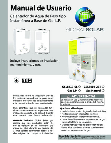
Transcription
INSTALLATION INSTRUCTIONSFOR UPFLOW & DOWNFLOW/HORIZONTAL HIGHEFFICIENCY CONDENSING GAS FURNACES90RJ AND 90TJ SERIES92-24161-32-08SUPERSEDES 92-24161-32-07
INSTALLATION CHECK LISTREFER TO INSTALLATION INSTRUCTIONSGAS SUPPLYAdequate pipe sizeTERMINATIONS – DIRECT VENTVERTICALCorrect supply pressure (during furnace operation)Intake – 12" min. above roof/snow levelManifold pressureCorrect relationship – exhaust to intakeNo gas leaksL.P. Kit Number (if applicable)ELECTRICAL115 V.A.C. supply (Single Circuit)Polarity observedHORIZONTAL/VERTICAL – CONCENTRIC (RXGY-E03)Intake – 12" min. above roof/snow levelIntake “Y” rotated above centerExhaust sloped toward furnaceHORIZONTAL – STANDARD (RXGY-D02, -D03)Furnace properly groundedCorrect relationship – exhaust to intakeAdequate wire size12" min. above grade/snow levelFURNACE INSTALLATIONHORIZONTAL – ALTERNATE (RXGY-D02, -D03 OR -D04)Adequate clearance to combustiblesCorrect relationship – exhaust to intakeAdequate clearance for service (at front)Above anticipated snow levelDUCT STATIC PRESSUREin. w.c. on heating speedin. w.c. on cooling speedAir temperature riseVENTING – NON-DIRECT VENTin. diameter – exhaust pipeft. of pipe – exhaustno. of elbowsCONDENSATE LINETERMINATION – NON-DIRECT VENTTrap filled with waterVERTICALVentedSloped toward drainCondensate drain line hoses connectedand clampedFreeze protection (if necessary)VENTING – DIRECT VENTHORIZONTAL – STANDARD12" min. above grade/snow levelHORIZONTAL – ALTERNATEAbove anticipated snow levelin. diameter – intake pipeModel Numberin. diameter – exhaust pipeSerial #ft. of pipe – intake airDate of Installationno. of elbows – intake airft. of pipe – exhaust pipeno. of elbows – exhaust pipeExhaust vent temp.212" min. above roof/snow level
IMPORTANT: All ICECO productsmeet current Federal OSHA Guidelinesfor safety. California Proposition 65warnings are required for certainproducts, which are not covered by theOSHA standards.California's Proposition 65 requireswarnings for products sold in Californiathat contain, or produce, any of over600 listed chemicals known to the Stateof California to cause cancer or birthdefects such as fiberglass insulation,lead in brass, and combustion productsfrom natural gas.CONTENTSSafety Precautions .1Installation Check List .2General Information.4Safety Information .5Location Requirements and Considerations .6Ducting .11Venting and Combustion Air Piping .12All “new equipment” shipped for sale inCalifornia will have labels stating thatthe product contains and/or producesProposition 65 chemicals. Although wehave not changed our processes,having the same label on all ourproducts facilitates manufacturing andshipping. We cannot always know“when, or if” products will be sold in theCalifornia market.Combustion and Ventilation Air.14You may receive inquiries fromcustomers about chemicals found in, orproduced by, some of our heating andair-conditioning equipment, or found innatural gas used with some of ourproducts. Listed below are thosechemicals and substances commonlyassociated with similar equipment inour industry and other manufacturers.Accessories .39 Glass Wool (Fiberglass) InsulationCarbon Monoxide (CO)FormaldehydeBenzeneMore details are available at theWebsites for OSHA (OccupationalSafety and Health Administration), atwww.osha.gov and the State ofCalifornia's OEHHA (Office ofEnvironmental Health HazardAssessment), at www.oehha.org.Consumer education is important sincethe chemicals and substances on thelist are found in our daily lives. Mostconsumers are aware that productspresent safety and health risks, whenimproperly used, handled andmaintained.Vent Pipe Installation.17Condensate Drain/Neutralizer.29Converting Downflow to Horizontal .31Gas Supply and Piping.33Electrical Wiring.38Furnace Twinning.39High Altitude Instructions.42Start-Up Procedures.45Air Flow.47Maintenance.50Troubleshooting.53Wiring Diagrams.54IMPORTANT: TO INSURE PROPER INSTALLATION AND OPERATION OFTHIS PRODUCT, COMPLETELY READ ALL INSTRUCTIONS PRIOR TOATTEMPTING TO ASSEMBLE, INSTALL, OPERATE, MAINTAIN OR REPAIRTHIS PRODUCT. UPON UNPACKING OF THE FURNACE, INSPECT ALLPARTS FOR DAMAGE PRIOR TO INSTALLATION AND START-UP.3
GENERAL INFORMATIONThe 90RJ and 90TJ series furnacesare design-certified by CSA for usewith natural and propane gases asfollows:1. As non-direct vent central forcedair furnaces taking combustionair from the installation area orusing air ducted from the outside.2. As direct vent central forced airfurnaces with all combustion airsupplied directly to the furnaceburners through a special airintake system outlined in theseinstructions.Install this furnace in accordance withthe American National StandardZ223.1 – latest edition entitled“National Fuel Gas Code” (NFPA54)and requirements or codes of thelocal utilities or other authoritieshaving jurisdiction. This is availablefrom the following:CSA-INTERNATIONAL8501 East Pleasant Valley RoadCleveland, Ohio 44131-5575National Fire ProtectionAssociation, Inc.Batterymarch ParkQuincy, MA 02269CSA-INTERNATIONAL178 Rexdale Blvd.Toronto, OntarioCanada M9W, 1R3Install units in Canada in accordancewith CSA-B149, local installationcodes and authorities havingjurisdiction. CSA-B149 is availablefrom:FIGURE 1FIGURE 2UPFLOW FURNACEDOWNFLOW/HORIZONTAL FURNACEI409ITEMNO.1234567891011124PART NAMECONDENSATE TRAPDOOR SWITCHJUNCTION BOXTRANSFORMERBLOCKED DRAIN PRESSURE SWITCHMAIN PRESSURE SWITCHEXHAUST TRANSITIONCONNECTOROUTLET AIR PIPESHIPPING PLUGFLAME SENSOROVERTEMPERATURE SWITCHITEMNO.13141516171819202122PART NAMETOP PLATEBURNERIGNITER (HSI ONLY)COMBUSTION AIR INLETGAS VALVEINDUCED DRAFT BLOWERCAPACITORLOW VOLTAGE (THERMOSTAT)TERMINALCONTROL MOUNTING PLATEBLOWERI409ITEMNO.12345678910111213PART NAMEINDUCED DRAFT BLOWERCAPACITORINLET AIR CHASEDOOR SWITCHJUNCTION BOXINLET PIPE CONNECTORTOP PLATECONTROL MOUNTING PLATEAUXILIARY LIMITSHIPPING PLUGEXHAUST CONNECTIONBLOWEREXHAUST PIPE EXTENSIONITEMNO.1415161718192021222324252627PART NAMELOW VOLTAGE TERMINAL (THERMOSTAT)TRANSFORMERPRESSURE SWITCHOUTLET AIR PIPEGAS VALVECONNECTOREXHAUST TRANSITIONCONDENSATE TRAPIGNITER (HSI)MANIFOLDOVERTEMPERATURE SWITCHROLLOUT SWITCHFLAME SENSORBURNER
SAFETY INFORMATION!WARNINGUSE ONLY WITH TYPE OF GASAPPROVED FOR THIS FURNACE.REFER TO THE FURNACE RATINGPLATE.!WARNINGINSTALL THIS FURNACE ONLY INA LOCATION AND POSITION ASSPECIFIED IN THE LOCATIONREQUIREMENTS ANDCONSIDERATIONS SECTION OFTHESE INSTRUCTIONS. PROVIDEADEQUATE COMBUSTION ANDVENTILATION AIR TO THEFURNACE SPACE AS SPECIFIEDIN THE VENTING SECTION OFTHESE INSTRUCTIONS.!WARNINGPROVIDE ADEQUATECOMBUSTION AND VENTILATIONAIR TO THE FURNACE SPACE ASSPECIFIED IN THE COMBUSTIONAND VENTILATION AIR SECTIONOF THESE INSTRUCTIONS.!NEVER TEST FOR GAS LEAKSWITH AN OPEN FLAME. USE ACOMMERCIALLY AVAILABLESOAP SOLUTION MADESPECIFICALLY FOR THEDETECTION OF LEAKS TO CHECKALL CONNECTIONS, ASSPECIFIED IN GAS SUPPLY ANDPIPING SECTION OF THESEINSTRUCTIONS.! WARNINGALWAYS INSTALL FURNACE TOOPERATE WITHIN THEFURNACE'S INTENDEDTEMPERATURE-RISE RANGEWITH A DUCT SYSTEM WHICHHAS AN EXTERNAL STATICPRESSURE WITHIN THEALLOWABLE RANGE, ASSPECIFIED IN DUCTING SECTIONOF THESE INSTRUCTIONS. SEEALSO FURNACE RATING PLATE.!WARNING!WARNINGDO NOT OPERATE THE SYSTEMFOR EXTENDED PERIODSWITHOUT FILTERS. A PORTIONOF THE DUST ENTRAINED IN THEAIR MAY TEMPORARILY LODGEIN THE AIR DUCT RUNS AND ATTHE SUPPLY REGISTERS. ANYCIRCULATED DUST PARTICLESWILL BE HEATED AND CHARREDBY CONTACT WITH THEFURNACE HEAT EXCHANGER.THIS SOOTY RESIDUE WILL SOILCEILINGS, WALLS, DRAPES,CARPETS AND OTHERHOUSEHOLD ARTICLES. SOOTDAMAGE MAY ALSO RESULTWITH, OR WITHOUT, FILTERS INPLACE, WHEN CERTAIN TYPESOF CANDLES ARE BURNED, ORCANDLEWICKS ARE LEFTUNTRIMMED.!WARNINGWHEN THIS FURNACE ISINSTALLED IN A RESIDENTIALGARAGE, IT MUST BE INSTALLEDSO THE BURNERS AND IGNITIONSOURCE ARE LOCATED NO LESSTHAN 18 INCHES ABOVE THEFLOOR. THIS IS TO REDUCE THERISK OF IGNITING FLAMMABLEVAPORS WHICH MAYBE PRESENT IN A GARAGE.ALSO, THE FURNACE MUST BELOCATED OR PROTECTED TOAVOID PHYSICAL DAMAGE BYVEHICLES. FAILURE TO FOLLOWTHESE WARNINGS CAN CAUSE AFIRE OR EXPLOSION, RESULTINGIN PROPERTY DAMAGE,PERSONAL INJURY OR DEATH.!WARNINGINSTALLATION MUST COMPLYWITH ALL INSTALLATIONINSTRUCTIONS INCLUDING: PROPER VENT INSTALLATION;!COMBUSTION PRODUCTS MUSTBE DISCHARGED OUTDOORS.CONNECT THIS FURNACE TO ANAPPROVED VENT SYSTEM ONLY,AS SPECIFIED IN VENT PIPEINSTALLATION SECTION OFTHESE INSTRUCTIONS.WARNINGWARNINGWHEN A FURNACE IS INSTALLEDSO THAT SUPPLY DUCTS CARRYAIR CIRCULATED BY THEFURNACE TO AREAS OUTSIDETHE SPACE CONTAINING THEFURNACE, THE RETURN AIRSHALL ALSO BE HANDLED BYDUCT(S) SEALED TO THEFURNACE CASING ANDTERMINATING OUTSIDE THESPACE CONTAINING THEFURNACE.!WARNINGDO NOT INSTALL THIS FURNACEIN A MOBILE HOME!! THISFURNACE IS NOT APPROVEDFOR INSTALLATION IN A MOBILEHOME. DOING SO COULD CAUSEFIRE, PROPERTY DAMAGE,PERSONAL INJURY OR DEATH. FURNACE OPERATING UNDERTHERMOSTATIC CONTROL; RETURN AIR DUCT SEALED TOTHE FURNACE; AIR FILTERS IN PLACE; SET FURNACE INPUT RATEAND TEMPERATURE RISE PERRATING PLATE MARKING; MEANS FOR PROVIDINGOUTDOOR AIR REQUIRED FORCOMBUSTION; RETURN AIR TEMPERATUREMAINTAINED BETWEEN 55 F(13 C) AND 80 F (27 C); AND CLEAN FURNACE, DUCT WORKAND COMPONENTS UPONSUBSTANTIAL COMPLETION OFTHE CONSTRUCTIONPROCESS, AND VERIFYFURNACE OPERATINGCONDITIONS INCLUDINGIGNITION, INPUT RATE,TEMPERATURE RISE ANDVENTING, ACCORDING TO THEINSTRUCTIONS.5
LOCATION REQUIREMENTS AND CONSIDERATIONSGENERAL INFORMATION!WARNINGDO NOT USE THIS FURNACEDURING CONSTRUCTION IF AIRLADEN CORROSIVECOMPOUNDS ARE PRESENTSUCH AS CHLORINE ANDFLUORINE. OTHERWISE,PROVISIONS MUST BE TAKEN TOPROVIDE CLEAN,UNCONTAMINATEDCOMBUSTION AND VENTILATIONAIR TO THE FURNACE. FURNACECOMBUSTION AND VENTILATIONAIR CONTAMINATED WITH THESECOMPOUNDS FORMS ACIDSDURING COMBUSTION WHICHCORRODES THE HEATEXCHANGER AND COMPONENTPARTS. SOME OF THESECONTAMINANTS ARE FOUND IN,BUT NOT LIMITED TO, PANELING,DRY WALL, ADHESIVES, PAINTS,STAINES, VARNISHES, SEALERS,AND MASONRY CLEANINGMATERIALS.!WARNINGDO NOT INSTALL THIS FURNACEIN A MOBILE HOME!! This furnaceis not approved for installation in amobile home. Doing so could causeFIRE, PROPERTY DAMAGE,PERSONAL INJURY OR DEATH.!WARNINGWHEN THIS FURNACE ISINSTALLED IN A RESIDENTIALGARAGE, IT MUST BE INSTALLEDSO THE BURNERS AND IGNITIONSOURCE ARE LOCATED NO LESSTHAN 18 INCHES ABOVE THEFLOOR. THIS IS TO PREVENTTHE RISK OF IGNITINGFLAMMABLE VAPORS WHICHMAY BE PRESENT IN A GARAGE.ALSO, THE FURNACE MUST BELOCATED OR PROTECTED TOAVOID PHYSICAL DAMAGE BYVEHICLES. FAILURE TO FOLLOWTHESE WARNINGS CAN CAUSE AFIRE OR EXPLOSION, RESULTINGIN PROPERTY DAMAGE,PERSONAL INJURY OR DEATH.1. IMPORTANT: If installing theunit over a finished ceiling orliving area, be certain to install anauxiliary condensate drain panunder the entire unit. Thisauxiliary drain pan should extendunder any evaporator coilinstalled with the furnace and theopen portion of the condensatedrain assembly. See“Condensate Drain/Neutralizer”section for more details.2. IMPORTANT: If using a coolingevaporator coil with this furnace:a. be sure the air passes overthe heat exchanger beforepassing over the coolingcoil. The cooled air passingover the warm ambient airinside the heat exchangertubes can causecondensation inside the tubesresulting in corrosion andeventual failure.b. install a parallel duct systemto divert all the air from thefurnace allowing it to passover the cooling coil only. Usedampers or other means toprevent chilled air frompassing over the heatexchanger.If these are manual dampers, theymust be equipped to prevent heatingor cooling operation unless thedamper is in the full heat or coolposition.3. IMPORTANT: Install the furnacelevel. If it is not level, condensatecannot drain properly, possiblycausing furnace shut down.NOTE: These furnaces are approvedfor installation in attics, as well asalcoves, utility rooms, closets andcrawlspaces. Provisions must bemade to prevent freezing ofcondensate.4.! CAUTIONIf this furnace is installed in agarage, attic and/or anyunconditioned space, install aself-regulating heat tapearound the condensate trapand along the entire length ofthe condensate drain in theunconditioned space. SeeFigure 3.When the condensing horizontalgas furnace is installed in anunconditioned space where thetemperature would be capable ofreaching close to or below 32 F(0 C). a self-regulating heat tapeis required on the condensatedrain, along with an insulationwrap. The heat tape should meetthe following requirements:a. The heat tape must be ULlisted.b. The heat tape must beinstalled per themanufacturer’s instructions forthe entire length of drain pipein the unconditioned space.c. The heat tape should be ratedFIGURE 3HORIZONTAL FURNACE W/HEAT TAPE ON CONDENSATE TRAPDRAINPIPEHEATTAPETRAPI5266
at 5 or 6 watts per foot at120V.IMPORTANT: Support this unitwhen installed. Since this furnaceis suitable for attic or crawl spaceinstallation, it may be installed oncombustible wood flooring or byusing support brackets. SeeFigure 4.FIGURE 4HORIZONTAL FURNACE INSTALLED W/SUPPORT BRACKETSGASPIPEINTAKEVENTELECTRICALCONDUIT5. IMPORTANT: If installing in autility room, be sure the dooris wide enough to:a. allow the largest part of thefurnace to pass; orb. allow any other appliance(such as a water heater)to pass.EXHAUSTFAN6. IMPORTANT: This furnace is notapproved or recommended forinstallation on its back, withaccess doors facing upwards.TRAPCLEARANCE ACCESSIBILITYThe design of forced air furnaces withinput ratings as listed in the tablesunder Figures 5, 6, and 7 are certifiedby CSA-International for theclearances to combustible materialsshown in inches.See name/rating plate and clearancelabel for specific model number andclearance information.Service clearance of at least 24inches is recommended in front ofall furnaces.NOTE: Use recommended 24”clearance if accessibility clearancesare greater than fire protectionclearances.! WARNINGUPFLOWAND HORIZONTALFURNACES ARE DESIGNCERTIFIED FOR INSTALLATIONON COMBUSTIBLE FLOORS.NOTE, HOWEVER, THATFURNACES MUST NOT BEINSTALLED DIRECTLY ONCARPETING, TILE OR OTHERCOMBUSTIBLE MATERIAL OTHERTHAN WOOD FLOORING.INSTALLATION ON ACOMBUSTIBLE MATERIAL CANRESULT IN FIRE, CAUSINGPROPERTY DAMAGE, PERSONALINJURY OR DEATH.Upflow furnaces are shipped with abottom closure panel installed.When bottom return air is used,remove the panel by removing thetwo screws attaching the panel tothe front base angle. See Figure 50.SITE SELECTION1. Select a site in the building nearthe center of the proposed, orexisting, duct system.2. Give consideration to the ventsystem piping when selecting thefurnace location. Be sure theventing system can get from thefurnace to the termination withminimal length and elbows.3. Locate the furnace near theexisting gas piping. Or, if runninga new gas line, locate thefurnace to minimize the lengthand elbows in the gas piping.4. Locate the furnace to maintainproper clearance to combustiblesas shown in the following tables.!I522WARNINGCOMBUSTIBLE MATERIAL MUSTNOT BE PLACED ON OR AGAINSTTHE FURNACE JACKET. THEAREA AROUND THE FURNACEMUST BE KEPT CLEAR AND FREEOF ALL COMBUSTIBLEMATERIALS INCLUDINGGASOLINE AND OTHERFLAMMABLE VAPORS ANDLIQUIDS. PLACEMENT OFCOMBUSTIBLE MATERIALS ON,AGAINST OR AROUND THEFURNACE JACKET CAN CAUSEAN EXPLOSION OR FIRERESULTING IN PROPERTYDAMAGE, PERSONAL INJURY ORDEATH. THE HOMEOWNERSHOULD BE CAUTIONED THATTHE FURNACE AREA MUST NOTBE USED AS A BROOM CLOSETOR FOR ANY OTHER STORAGEPURPOSES.! WARNINGDO NOT LIFT THE UNIT BY THEHEAT EXCHANGER TUBES.DOING SO CAN CRACK THE HEATEXCHANGER ASSEMBLY ANDCAUSE CO2 TO BE RELEASEDINTO THE ENVIRONMENT, WHICHCAN RESULT IN PERSONALINJURY OR DEATH.7
8SUPPLYAIRAIRFLOWRETURNAIR225 8155 8222222D22181 2181 2151515E2025 32179 32179 321325 321325 321325 2*2*000000FRONT VENTMINIMUM CLEARANCE (IN.)RIGHTSIDE*A service clearance of at least 24 inches is recommended in front of all furnaces.2311 32241 212191 81927 322110191 81927 3207211611 32171 20609155 81611 32171 2155 81611 32171 204CBAMODELUPFLOW MODELS160152148123117111SHIPWGTSFIGURE 5CLEARANCE TO COMBUSTIBLES, UPFLOW UNITSI392
AIRFLOWSUPPLYAIR2311 32241 212225 8193 16155 8222222D235 8201 8201 8165 8165 8165 8E207 8173 8173 8137 8137 8137 *2*000000FRONT VENTMINIMUM CLEARANCE (IN.)RIGHTSIDE*A service clearance of at least 24 inches is recommended in front of all furnaces.1911 3209211911 32210710193 161611 32171 206NOTE: IN DOWNFLOW CONFIGURATION, OPTIONAL AIR CUTOUT IS NOT PERMITTED.RETURNAIR155 81611 32171 2155 81611 32171 204CBAMODELDOWNFLOW MODELS160152148123117111SHIPWGTSFIGURE 6CLEARANCE TO COMBUSTIBLES, DOWNFLOW UNITSI3939
10155 8193 16193 16193 161611 321611 321927 321927 321927 322311 32171 2171 2212121241 20607070910122222222D235 8201 8201 8201 8165 8165 8165 8E205 8173 8173 8173 8137 8137 8137 000000FRONT VENT160152148123123117111SHIPWGTSIMPORTANT: This furnace is not approved or recommended forinstallation on its back, with access doors facing upwards.1111111TOPMINIMUM CLEARANCE (IN.)RIGHTSIDE*A service clearance of at least 24 inches is recommended in front of all furnaces.225 8155 8155 81611 32171 204CBAMODELDOWNFLOW MODELSCLEARANCE TO COMBUSTIBLES, HORIZONTAL UNITSFIGURE 7I520
DUCTINGProper air flow is required for thecorrect operation of this furnace.Too little air flow can cause erraticoperation and can damage the heatexchanger. The duct system mustcarry the correct amount of air forheating and cooling if summer airconditioning is used.Size the ducts according toacceptable industry standards andmethods. The total static pressuredrop of the air distribution systemshould not exceed 0.5" w.c.NOTE: Return air grilles and warm airregisters must not be obstructed!WARNINGNEVER ALLOW THE PRODUCTSOF COMBUSTION FROM THEFLUE TO ENTER THE RETURN AIRDUCTWORK OR THECIRCULATED AIR SUPPLY. ALLRETURN DUCTWORK MUST BEADEQUATELY SEALED ANDSECURED TO THE FURNACEWITH SHEET METAL SCREWS;AND JOINTS, TAPED. ALL OTHERDUCT JOINTS MUST BE SECUREDWITH APPROVED CONNECTIONSAND SEALED AIRTIGHT. WHEN ANUPFLOW FURNACE IS MOUNTEDON A PLATFORM WITH RETURNTHROUGH THE BOTTOM, IT MUSTBE SEALED AIRTIGHT BETWEENTHE FURNACE AND THE RETURNAIR PLENUM. THE FLOOR ORPLATFORM MUST PROVIDESOUND PHYSICAL SUPPORT OFTHE FURNACE WITHOUTSAGGING, CRACKS, OR GAPS,AROUND THE BASE, PROVIDING ASEAL BETWEEN THE SUPPORTAND THE BASE.FAILURE TO PREVENTPRODUCTS OF COMBUSTIONFROM BEING CIRCULATED INTOTHE LIVING SPACE CAN CREATEPOTENTIALLY HAZARDOUSCONDITIONS, INCLUDINGCARBON MONOXIDE POISONINGTHAT COULD RESULT INPERSONAL INJURY OR DEATH.DO NOT, UNDER ANYCIRCUMSTANCES, CONNECTRETURN OR SUPPLY DUCTWORKTO OR FROM ANY OTHER HEATPRODUCING DEVICE SUCH AS AFIREPLACE INSERT, STOVE, ETC.DOING SO MAY RESULT IN FIRE,CARBON MONOXIDE POISONING,EXPLOSION, PERSONAL INJURYOR PROPERTY DAMAGE.IMPORTANT: Some high efficiencyfilters have a greater than normalresistance to air flow. This canadversely affect furnace operation.BE SURE TO CHECK AIR FLOW.IMPORTANT: When using outsideair, design and adjust the system tomaintain a return air temperatureABOVE 50 F during the heatingseason.UPFLOW UNITS1. Position the unit to minimize longruns of duct or runs of duct withmany turns and elbows.2. Open the return air compartment.!5. If summer air conditioning isdesired, position the indoor coilon the top of the unit. Insure thatno air can bypass this coil.6. Connect the supply air plenum tothe furnace plenum opening.WARNINGUPFLOW FURNACE: A SOLIDMETAL BASE PLATE MUST BEINSTALLED IN THE FURNACEBOTTOM WHEN USING SIDERETURN. FAILURE TO INSTALL ABASE PLATE COULD CAUSE THEPRODUCTS OF COMBUSTION TOCIRCULATE INTO THE LIVINGSPACE AND CREATE POTENTIALLY HAZARDOUS CONDITIONS,INCLUDING CARBON MONOXIDEPOISONING OR DEATH.a. Cut an opening in the side.The opening shouldbe cut the full width of theknockouts on the unit. SeeFigure 8.NOTE: Where the maximum air flowis 1800 CFM or more, both sides orthe bottom must be used for returnair.3. Connect the return duct or returnair cabinet to the unit. Make theconnection air tight to prevententraining combustion gasesfrom an adjacent fuel-burningappliance.4. Be sure to have adequatespace for the unit filter.NOTE: DO NOT take return airfrom bathrooms, kitchens,furnace rooms, garages, utility orlaundry rooms, or cold areas.IMPORTANT: If a flexible ductconnector must be used, itMUST be rated for a minimumtemperature of 250 F.continuous.DOWNFLOW UNITS1. Position the unit to minimize longruns of duct or runs of duct withmany turns and elbows.2. If summer air conditioning isdesired, position the indoor coilon the bottom of the unit. Insurethat no air can bypass this coil.3. If installing on a combustible floorand not using an airconditioning plenum, install thespecial non-combustible floorbase. See Figure 9.!WARNINGTHE DOWNFLOW FURNACEDESIGN IS CERTIFIED FORINSTALLATION ON A NONCOMBUSTIBLE FLOOR. USE THESPECIAL BASE SPECIFIED ONTHE FURNACE CLEARANCELABEL. FAILURE TO INSTALL THESPECIAL BASE MAY RESULT INFIRE, PROPERTY DAMAGE,PERSONAL INJURY OR DEATH.THIS SPECIAL BASE IS SHIPPEDFROM THE FACTORY AS ANACCESSORY.NOTE: DO NOT use a rear airreturn.FIGURE 8CUTOUT AND DRILL INFORMATIONJACKETDRILL (2)3/16" DIA.HOLES8.0004.8751.53111
4. Connect the furnace to thesupply air plenum.5. Connect the return air ducting tothe return air opening at the topof the unit. Make the connectionair tight to prevent entrainingcombustion gases from anadjacent fuel-burning appliance.6. Be sure to have adequatespace for the unit filter.NOTE: DO NOT take return airfrom bathrooms, kitchens,furnace rooms, garages, utility orlaundry rooms, or cold areas.end of the unit. Make theconnection air tight to preventpulling combustion gases froman adjacent fuel-burningappliance.5. Be sure to have adequatespace for the unit filter.NOTE: DO NOT take return airfrom bathrooms, kitchens,furnace rooms, garages, utility orlaundry rooms, or cold areas.FIGURE 9NON-COMBUSTIBLE FLOOR BASEHORIZONTAL UNITIMPORTANT: This furnace may onlybe installed so as when facing thefront of the furnace, supply air isdischarged on the left hand side.1. Position the unit to minimize longruns or runs with many turns andelbows.2. If summer air conditioning isdesired, position the indoor coilon the left end of the unit. Insurethat no air can bypass this coil.3. Connect the furnace to thesupply air plenum.4. Connect the return air ducting tothe return air opening at the rightVENTING AND COMBUSTION AIR PIPINGGENERAL INFORMATION!WARNINGREAD AND FOLLOW ALLINSTRUCTIONS IN THIS SECTION.FAILURE TO PROPERLY VENTTHIS FURNACE CAN CAUSECARBON MONOXIDE POISONINGOR AN EXPLOSION OR FIRE,RESULTING IN PROPERTYDAMAGE, PERSONAL INJURYOR DEATH.This furnace removes both sensibleand latent heat from the combustionflue gases. Removal of latent heatresults in condensation of flue gaswater vapor. This condensed watervapor drains from the secondary heatexchanger and out of the unit into adrain trap.When installed as a non-direct ventfurnace, only exhaust piping isrequired and inside combustion airmay be used. Refer to section on“COMBUSTION & VENTILATION AIRFOR FURNACE INSTALLATIONS.”Direct vent installations require adedicated combustion air and ventingsystem. All air for combustion is takenfrom the outside atmosphere and allcombustion products are dischargedto the outdoors.12The combustion air and vent pipefittings must conform to AmericanNational Standards Institute (ANSI)and American Society for TestingMaterials (ASTM) standardsD1785 (Schedule 40 PVC), D2665(PVC-DWV), D2241 (SDR-21 andSDR26-26 PVC), D2661 (ABS-DWV)or F628 (Schedule 40 ABS-DWV).NOTE: Cellular core PVC is alsoapproved for use. It must be schedule40PVC-DWV cellular pipemanufactured under ASTM F-891.IMPORTANT: The plastic combustionair and venting components are ofSchedule 40 PVC. If using ABSpiping, ensure that the solventcement is compatible for joining PVCto ABS components or use amechanical connection that canwithstand the vent temperatures andare corrosion resistant.NOTE: Schedule 40 ABS-DWV pipeand fittings may be used as analternate to PVC pipe for thecombustion air inlet and vent pipes.OVERTEMPERATURESAFETY SWITCHESFurnaces are equipped with safetyswitches in the control compartmentto protect against overtemperatureconditions caused by inadequatecombustion air supply. The switchesfor the upflow and downflow modelsare located in the burnercompartment. If a switch is tripped itmust be manually reset.!WARNINGDO NOT JUMPER THESEDEVICES! IF ONE OF THESESWITCHES SHOULD TRIP, AQUALIFIED INSTALLER, SERVICEAGENCY OR THE GAS SUPPLIERMUST BE CALLED TO CHECKAND/OR CORRECT FORADEQUATE COMBUSTION AIRSUPPLY. DO NOT RESET THESWITCHES WITHOUT TAKINGCORRECTIVE ACTION TO ASSURETHAT AN ADEQUATE SUPPLY OFCOMBUSTION AIR IS MAINTAINEDUNDER ALL CONDITIONS OFOPERATION. FAILURE TO DO SOCAN RESULT IN CARBONMONOXIDE POISONING ORDEATH. IF THIS UNIT IS MOUNTEDIN A CLOSET, THE DOOR MUSTBE CLOSED WHEN MAKING THISCHECK.REPLACE THESE SWITCHESONLY WITH THE IDENTICALREPLACEMENT PART.EXISTING VENT SYSTEMSWhen the installation of this furnacereplaces an existing furnace that is
removed from a vent system servingother appliances, the vent system islikely to be too large to properly ventthe remaining attached appliances.The following steps should befollowed with each applianceremaining connected to the originalcommon vent system. Place theappliance to be tested in operation,while the other appliances remainingconnected to the common ventsystem are not in operation. Test theoperation of each applianceindividually by the following method.1. Permanently seal any unusedopenings in the common ventingsystem.2. Visually inspect the ventingsystem for proper size andhorizontal pitch and determinethat there is no blockage,restriction, leakage, corrosion orother deficiencies which couldcause an unsafe condition.3. If practical, close all buildingdoors, windows and all doorsbetween the space where theappliances remaining connectedto the common venting systemare located.Turn on clothes dryers and anyappliance not connected to thecommon venting system. Turn onany exhaust fans, such as rangehoods and bathroom exhausts,so they will operate at maximumspeed. Do not operate a summerexhaust fan. Close fireplacedampers.4. Follow the lighting instructions.Place the appliance beinginspected into operation. Adjustthe thermostat so the appliancewill operate continuously.5. Test for spillage at the draft hoodrelief opening after 5 minutes ofmain burner operation. Use theflame of a match or candle, orsmoke from a cigarette, cigaror pipe.6. After it has been determined thateach appliance that remainsconnected to the commonventing system properly vents(when tested as outlined above),return doors, windows, exhaustfans, fireplace dampers and anyother gas-burning appliance totheir previous conditions of use.7. If improper venting is observedduring any of the above tests, thecommon venting system must beresized. See vent tables in theseinstructionsWhen the furnace is installed in thesame space with other gasappliances such as a water heater, besure there is an adequate supply ofcombustion and ventilation air for theother appliances. Do not delete orreduce the combustion air supplyrequired by the other gas appliancesin this space. See Z223.1, NationalFuel Gas Code (NFPA54) fordetermining the combustion airrequirements for gas appliances. Anunconfined space must have at least50 cubic feet (volume) for each1,000 BTUH of the total input of allappliances in the space. If the openspace containing the appliances is ina building with tight construction(contemporary construction), outsideair may still be required for theappliances to burn and vent properly.Outside air openings should be sizedthe same as for a confined space.JOINING PIPE ANDFITTINGS!WARNINGPVC SOLVENT CEMENTS ANDPRIMERS ARE HIGHLYFLAMMABLE. PROVIDEADEQUATE VENTILATION AND DONOT ASSEMBLE NEAR HEATSOURCE OR AN OPEN FLAME. DONOT SMOKE. AVOID SKIN OR EYECONTACT. OBSERVE A
furnace casing and terminating outside the space containing the furnace. when this furnace is installed in a residential garage, it must be installed so the burners and ignition source are located no less than 18 inches above the floor. this is to reduce the risk of igniting flammable vapors which may be present in a garage. also, the furnace .