Transcription
DatasheeteMMC v1.5 Total IP SolutionIncluding eMMC 5.1 PHY in 40nm, 28nm and 16nm FinFET (16FF )eMMC Spec Version 5.1 CompliantArasan Chip Systems Inc.2010 North First Street, Suite #510, San Jose, CA 95131Ph: 408-282-1600Fax: 408-282-7800www.arasan.com
DatasheetDisclaimerThis document is written in good faith with the intent to assist the readers in the use of the product.Circuit diagrams and other information relating to Arasan Chip Systems’ products are included as ameans of illustrating typical applications. Although the information has been checked and isbelieved to be accurate, no responsibility is assumed for inaccuracies. Information contained in thisdocument is subject to continuous improvement and development.Arasan Chip Systems’ products are not designed, intended, authorized or warranted for use in anylife support or other application where product failure could cause or contribute to personal injuryor severe property damage. Any and all such uses without prior written approval of an Officer ofArasan Chip Systems Inc. will be fully at the risk of the customer.Arasan Chip Systems Inc. disclaims and excludes any and all warranties, including, withoutlimitation, any and all implied warranties of merchantability, fitness for a particular purpose, title,and infringement and the like, and any and all warranties arising from any course or dealing orusage of trade.This document may not be copied, reproduced, or transmitted to others in any manner. Nor mayany use of information in this document be made, except for the specific purposes for which it istransmitted to the recipient, without the prior written consent of Arasan Chip Systems Inc. Thisspecification is subject to change at any time without notice. Arasan Chip Systems Inc. is notresponsible for any errors contained herein.In no event shall Arasan Chip Systems Inc. be liable for any direct, indirect, incidental, special,punitive, or consequential damages; or for loss of data, profits, savings or revenues of any kind;regardless of the form of action, whether based on contract; tort; negligence of Arasan ChipSystems Inc or others; strict liability; breach of warranty; or otherwise; whether or not any remedyof buyers is held to have failed of its essential purpose, and whether or not Arasan Chip SystemsInc. has been advised of the possibility of such damages.Restricted RightsUse, duplication, or disclosure by the Government is subject to restrictions as set forth inFAR52.227-14 and DFAR252.227-7013 et seq. or its successor.Copyright NoticeNo part of this specification may be reproduced in any form or means, without the prior writtenconsent of Arasan Chip Systems, Inc.Questions or comments may be directed to:Arasan Chip Systems Inc.2010 North First Street, Suite 510San Jose, CA 95131Ph: 408-282-1600Fax: 408-282-7800Copyright 2015, Arasan Chip Systems Inc.
DatasheetContents1Introduction . 11.11.21.32About eMMC . 1Arasan’s Contribution to JEDEC and SD Association . 1Arasan’s Total IP Solution . 2eMMC 5.1 Host Controller Datasheet. 32.1 Overview . 32.2 Features . 32.3 Architecture. 42.3.1Functional Description . 42.3.2Functional Block Diagram . 52.3.3Functional Block Diagram Description . 52.4 Pinouts. 82.4.1I/ O Description . 82.5 IP Deliverables for RTL Version . 192.6 Verification Environment . 193eMMC 5.1 Host PHY Datsheet . 213.1 Overview . 213.2 Features . 213.3 Architecture. 213.3.11HS400 Overview . 213.4 Signal Interface . 243.5 DC Characteristics . 303.5.1Driver Strength Support . 313.6 Deliverables . 314eMMC 5.1 Device Controller Datasheet . 324.1 Overview . 324.2 Features . 324.3 Architecture. 344.3.1Functional Description . 344.3.2Functional Block Diagram . 344.3.3Functional Block Diagram Description . 354.4 Signal Interfaces . 364.5 SOC Level Integration . 404.5.1Verification Environment . 404.5.2Verification Deliverables . 404.5.3IP Deliverables . 40Copyright 2015, Arasan Chip Systems Inc.
Datasheet5eMMC Device I/ O Datasheet . 415.1 Overview . 415.2 Features . 415.3 Architecture. 415.3.1eMMC 5.1 I/ O Overview . 415.4 Signal Interfaces . 425.5 I/ O Configuration Settings . 435.6 DC Characteristics . 435.6.1Driver Strength Support . 445.7 Deliverables . 446Hardware Validation Platform . 456.16.26.36.47eMMC 5.1 NEXBus Driver . 487.17.27.37.48Overview . 45Features . 46HVP Architecture . 46Deliverables . 47Overview . 48Features . 48Architecture. 49Deliverables . 49Services & Support . 508.18.28.38.48.5Global Support . 50Arasan Support Team . 50Professional Services & Customization . 50The Arasan Porting Engine . 50Pricing & Licensing . 50TablesTable 1: AHB Bus Interface Signals. 8Table 2: OCP Bus Interface Signals . 9Table 3: AXI Bus Interface Signals . 10Table 4: SD3.0/SDIO3.0/eMMC5.0 Interface . 13Table 5: Power Control Signals (Used for SD/SDIO Mode only) . 14Table 6: Clock, Special Controls and Test Mode Signals . 14Table 7: Block RAM (SRAM) Interface Signals . 15Table 8: Core Configuration Signals . 16Copyright 2015, Arasan Chip Systems Inc.
DatasheetTable 9: eMMC5.1 Pin Description . 24Table 10: Recommended Operating Conditions . 30Table 11: DC Characteristics . 30Table 12: Drive Strength . 31Table 13: eMMC Bus Interface Signals. 36Table 14: AHB Target Interface Signals: . 37Table 15: AHB Master Interface Signals . 37Table 16: 128x32 Dual-Port RAM1 Interface Signals . 38Table 17: 128x32 Dual-Port RAM2 Interface Signals . 39Table 18: 128x32 RAM Interface Signals. 39Table 19: 32x32 fifo Interface signals . 39Table 20: Pin Details for eMMC5.1 I/O PAD . 42Table 21: Pad Mode of Operation Programming . 43Table 22: Recommended Operating Conditions . 43Table 23: DC Characteristics . 43Table 24: Drive Strength . 44FiguresFigure 1: Arasan’s Total IP Solution . 2Figure 2: eMMC5.1/SD3.0/SDIO3.0 Host Controller Functional Block Diagram . 5Figure 3: Verification Environment . 20Figure 4: HS400 Block Diagram . 22Figure 5: eMMC5.1 PHY I/O Diagram . 23Figure 6: Device Controller Functional Block Diagram . 34Figure 7: Verification Environment of eMMC 5.1 Device . 40Figure 8: eMMC 5.1 I/O Block Diagram . 42Figure 9: Photo of Arasan’s Hardware Validation Platform . 45Figure 10: HVP Architecture. 47Figure 11: eMMC 5.1 Bus Driver Architecture . 49Copyright 2015, Arasan Chip Systems Inc.
Datasheet1 Introduction1.1 About eMMCeMMC, short for "embedded Multi-Media Card", is an embedded non-volatile memory system,comprised of both flash memory and a flash memory controller integrated in the same industrystandard BGA package.eMMC architecture, integrating the flash memory and controller in the same package, simplifies theapplication interface design and frees the host processor from low-level flash memorymanagement. This benefits product developers by simplifying the non-volatile memory interfacedesign and qualification process – resulting in reducing time-to-market, as well as future proofingagainst new flash memory technology advances.The eMMC standard has been developed and published by JEDEC Solid State TechnologyAssociation (www.jedec.org), the global leader in the development of standards for themicroelectronics industry. JEDEC has over 4,000 participants, representing nearly 300 companies,working together in 50 JEDEC committees.The latest revision of the JEDEC standard is 5.0, released on Sep. 2013, and defines a maximumbandwidth of 400 MB/s over 8 data lanes. The combination of 200 MHz DDR clock rate, and 8 datalanes, requires the use of a hard PHY. Arasan has designed the analog PHY in 40nm, 28nm, and16nm FinFET process technologies, and are all silicon proven. Latest eMMC revision of the JEDECabout to be released is eMMC5.1 (Item # JC-64.1-67.14).1.2 Arasan’s Contribution to JEDEC and SD AssociationArasan Chip Systems has been an executive member with the Multi Media Card Association(MMCA) since 2002. The MMCA was later merged with JEDEC in 2008 as the emphasis of MMCAshifted from removable storage to embedded storage for mobile devices. Arasan is currently acontributing member to JEDEC actively promoting both the eMMC and UFS standards. Arasan isalso a contributing member to the SD Association since 2001.Arasan is the leader of mobile storage, with 300 IP licensees since 2002 for SD, SDIO, NAND, eMMCand UFS. Our eMMC Host and Device IPs were licensed to both Application Processor companieslike Intel, LG, Samsung and Huawei, as well as the majority of the Memory companies, and includesSK Hynix, among others.Arasan’s active involvement and contribution to the relevant standards bodies, lead to deepdomain expertise, which in turn results in early availability of high quality IP for our customers.Copyright 2015, Arasan Chip Systems Inc.1
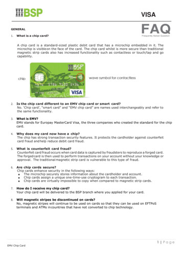
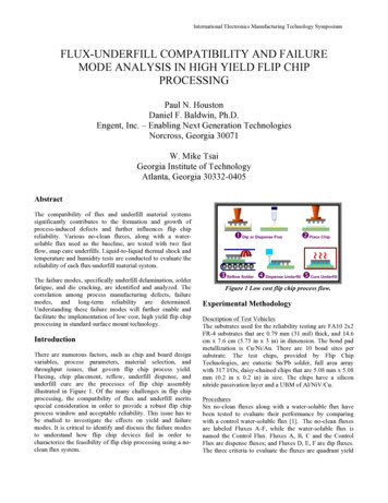
Datasheet1.3 Arasan’s Total IP SolutionArasan provides a Total IP Solution, which encompasses all aspects of IP development andintegration, including analog and digital IP cores, verification IP, software stacks & drivers, andhardware validation platforms.Benefits of Total IP Solution: Seamless integration from PHY to SoftwareAssured compliance across all componentsSingle point of supportEasiest acquisition process (one licensing source)Lowest overall cost including cost of integrationLowest risk for fast time to marketFigure 1: Arasan’s Total IP SolutionCopyright 2015, Arasan Chip Systems Inc.2
Datasheet2 eMMC 5.1 Host Controller Datasheet2.1 OverviewArasan Chip Systems’ eMMC5.1 Host Controller IP is a highly integrated Intellectual Property (IP)solution that supports three key memory and I/O technologies:1.2.3.4.JEDEC eMMC (eMMC Multi Media Card) 5.1 (Draft)JEDEC eMMC CQHCI for Command QueueingSDA Secured Digital (SD) 3.01SDA Secured Digital Input Output (SDIO) 3.01This IP handles all the timing and interface protocol requirements to access these media as well asprocessing the commands in hardware.The IP supports connection to a single slot and performs multi-block writes and erases that loweraccess overhead. In addition, a host can utilize this IP to boot directly from an attached eMMCdevice, thereby simplifying system initialization during power up. The host interface is based on astandard 32-bit/64-bit Advanced High-Performance Bus (AHB/AXI/OCP) which is used to transferdata and configure the IP.2.2 Features Compliant with the following specifications: JEDEC eMMC Specification Version 5.1 JEDEC eMMC CQHCI (part of eMMC5.1) SDA Part A2 SD Host Controller Version 3.00 SDA Part 1 Physical Layer Specification Version 3.00 SDA Part E1 SDIO Specification Version 3.00 AMBA, AHB Specification Version 2.00 AMBA, Advanced Extensible Interface (AXI) Specification Version 1.00 (Optional) Open Core Protocol (OCP) Specification Version 2.2 (Optional) The core supports: 32-bit and 64-bit system data bus. 32-bit and 64-bit system addressing. Interrupts and wake up functionality Internal Clock divider for various card operational modes One of the AHB, AXI or OCP System/Host bus The data is transferred using: Programmed Input/Output (PIO) mode on the Host Bus Slave interfaceCopyright 2015, Arasan Chip Systems Inc.3
Datasheet Direct Memory Access (DMA) mode using Simple DMA (SDMA) or Advanced DMA (ADMA2)on the Host Bus Master interface*Configurable FIFO size to support different block sizes.Note: The Host Bus is AHB or AXI or OCP. eMMC 5.1 features: HS400 high speed interface timing mode of up to 400 MB/s data rate Transfers the data in HS400, HS200, DDR52 modes. 4KB block support Tuning for HS200 mode Command Queuing for High Performance data transfers with Hardware Acceleration. Enhanced strobe function for reliable operation at HS400 mode. MMC Plus and MMC Mobile Host clock rate variable between 0 and 200 MHz Transfers the data in 1-bit, 4-bit and 8-bit modes Supports legacy modes (Default Speed, High Speed). CRC7 for command and CRC16 for data integrity Password protection of cards UHS-I features (SD3.0/SDIO3.0): 1.8V voltages switch operation Tuning for SDR104 mode Host clock rate variable between 0 and 208 MHz Up to 832 Mbps data rate using 4 parallel data lines (SDR104 mode) Transfers the data in 1-bit and 4-bit SD modes. Transfers the data in SDR104, DDR50, SDR50, SDR25, SDR12, DS and HS modes Cyclic Redundancy Check (CRC): CRC7 for commands, CRC16 for data integrity Variable-length data transfers Performs Read Wait Control, Suspend/Resume operation with SDIO CARD Designed to work with I/O cards, Read-only cards and Read/Write cards Card Detection (Insertion/Removal)2.3 Architecture2.3.1 Functional DescriptionThe Arasan eMMC5.1 Host Controller is a Host Controller with an AHB/AXI/OCP processor interface.This product conforms to upcoming eMMC5.1 Specification from JEDEC. It is also compliant SD HostController Standard Specification Version 3.00.The eMMC5.1 Host Controller handles eMMC (and also SDIO/SD) Protocol at transmission level,packing data, adding CRC, start/end bit, and checking for transaction format correctness. This HostCopyright 2015, Arasan Chip Systems Inc.4
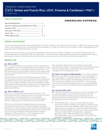
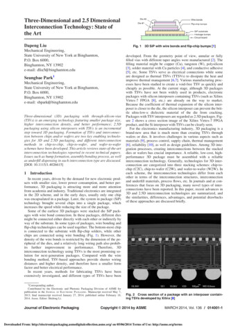
DatasheetController provides Programmed IO method and DMA data transfer method. In programmed IOmethod, the Host processor transfers data using the Buffer Data Port Register.The eMMC 5.1 Host Controller support for DMA can be determined by checking the DMA support inthe capabilities register. DMA allows a peripheral to read or write memory without the interventionfrom the CPU. This Host Controller’s Host Controller system address register points to the first dataaddress, and then data is accessed sequentially from that address. It supports connection to a singleslot and performs multi-block writes and erases the lower access. The eMMC5.1 Host Controllersupports two DMA schemes: Simple DMA (SDMA) and Advanced DMA (ADMA2)2.3.2 Functional Block DiagramFigure 2: eMMC5.1/SD3.0/SDIO3.0 Host Controller Functional Block Diagram2.3.3 Functional Block Diagram Description2.3.3.1 Host Interface (Master/ Target)The Master Bus Interface is used to access the DMA Controller (when using DMA) or AdvancedDirect Memory Access (ADMA2 Modes). The DMA Controller module interfaces with the Host(AHB/AXI/OCP) Master Module to generate Transfers and on the other side it interfaces with theBlock Buffer to store/fetch block data. The DMA Controller implements a separate DMA for SimpleDirect Memory Access (SDMA) Operation and Separate DMA for the ADMA2 Operation. In addition,it implements Host Transaction Generator that generates controls for the Host Master InterfaceModule.Copyright 2015, Arasan Chip Systems Inc.5
DatasheetThe DMA Controller uses the Master DMA interfaces to transfer data between the Host Controllerand the System Memory and vice-versa and also to fetch the descriptors while operating in ADMA2mode.The Host Controller interfaces with the System bus using the AHB, AXI, or OCP Master and SlaveInterface. The Slave Interface is used to access the Registers inside the Host controller. The SlaveInterface supports only single transfer access (no Burst Support) and only one outstandingRead/Write transaction in case of AXI or OCP interface.2.3.3.2 Host DMAThe PIO/DMA Controller module implements the SDMA and ADMA2 engines as defined in the SDHost Controller specification and maintains the block transfer counts for PIO operation. It interactswith the Registers Set and starts the DMA engine when a Command with Data Transfer is involved.The DMA Controller interfaces with the Host (AHB/AXI/OCP) Master module to generate Transfersand on the other side it interfaces with the Block Buffer to store/fetch block data. It implements aseparate DMA for SDMA operation and separate DMA for the ADMA2 operation. In additionimplements Host Transaction Generator that generates controls for the Host Master interfacemodule.2.3.3.3 Command Queuing EngineThe Command Queueing Engine implements the context for 32 Tasks and is compliant with theCQHCI specification. This will drastically reduce the software overhead for data transfers by queuingup the tasks to the eMMC 5.1 compliant device and polling the device and performing the datatransfers associated with these tasks.The Command Queuing Engine controls the Host DMA and the Host Registers based on the activeTask and tasks that are ready.2.3.3.4 eMMC/ SD Host RegisterThe Host Controller Register Set implements the Registers defined by the SD Host ControllerSpecification. The Registers are Byte/DWORD accessible from the Slave interface. The HostController Register Set also implements the Data Port Registers for the PIO Mode transfers.The Register Set provides the control signals and monitors the status signals from the blocks to setInterrupt Status Bits and eventually generate Interrupt signal to the Host Bus.2.3.3.5 Block BufferThe SD/SDIO Host Controller uses a Dual Port Block Buffer (Read/Write on both ports) or a Two Port(One Read/One Write) that is used to store the Block Data during SD Transfers. The size of the BlockBuffer is Configurable and has to be a minimum of 1 Block Size (Block Size is 512 Bytes in eMMC/SDMemory and up to 2K Bytes in SDIO).Copyright 2015, Arasan Chip Systems Inc.6
DatasheetTo achieve maximum performance the Block buffer has to be sized to twice the maximum Block Sizesupported by Host Controller. The Block Buffer uses Circular Buffer Architecture. One side of theBlock Buffer is interfaced with the DMA Controller and operates on the Host Clock. The other sideof the Block Buffer interfaces with eMMC/SD Interface Control Logic and operates on eMMC/SDClock. During a write transaction (data transferred from a Host Processor toeMMC5.1/SD3.0/SDIO3.0 card), the data is fetched from the Host System Memory and is stored inthe Block Buffer. When a Block of data is available, the SD Control logic will transfer it onto theeMMC Interface.The DMA Controller continues to fetch additional block of data when the Block Buffer has space.During a Read transaction (data transferred from eMMC5.1/SD3.0/SDIO3.0 card to Host Processor),the data from eMMC5.1 card will be written in to Block Buffer and at the end when the CRC of theBlock is valid, the data is committed. When a Block of data is available, then the DMA Controllertransfers this data to the Host System Memory. The eMMC/SD Interface Control logic meanwhilereceives the next Block of data provided there is space in the Block Buffer. If the Host controllercannot accept any data from eMMC5.10 card, then it will issue Read Wait (if card supports ReadWait mechanism) to stop the data transfer from card or by stopping the clock.Note: FIFO depth can be varied using parameter passed to the Core using the ‘dot parameterinstantiation’. When the Block Buffer size is twice that of the Block Size, the Block Buffer behaveslike a ping-pong buffer.2.3.3.6 eMMC/ SD (UHS – I) Interface Control (CMD/ DAT/ RES)The eMMC/SD Interface Control block maps the internal signals to the External eMMC/SD Interfaceand vice versa. Based on the Bus Width (1/4/8) the internal signals are driven out appropriately. Incase of DS, the outputs are driven on the negative edge of the sd clk.This module performs the Tuning procedure for HS200 (or SDR104) modes to center align thereceive clock to the incoming data stream.2.3.3.7 Clock/ Power ManagementThe eMMC/SD Interface Clock Generator module generates the eMMC/SD Clock from theReference Clock (xin clk), based on the Controls programmed in the Clock Control Register. Theseinclude the Clock Divide Value, Clock Enable and so on. The outputs from this module are theEMMC CLK/SD CLK and the CARD Clock. The EMMC/SD CLK is used by the eMMC/SD InterfaceControl Logic and the CARD Clock connected to the “CLK” Pin on the SD/EMMC Interface. Thismodule also generates system resets to various clock domains.Copyright 2015, Arasan Chip Systems Inc.7
Datasheet2.4 Pinouts2.4.1 I/ O DescriptionThe Arasan eMMC5.1 Host Controller has the following interface groups. System (AHB/AXI/OCP) Bus Interface SignalseMMC5.1 SD3.0 / SDIO3.0 / eMMC5.0 Interface that forms the main card interfacePower Control SignalsClock, Special Controls and Test Mode SignalsBlock RAM, Static Random Access Memory (SRAM) Interface SignalsCore Configuration SignalsNote:1. AW is the Address width on the Master Bus which is 32/ 64-bits based on configuration2. DW is the Data width on the Master bus which is 32/64-bits based on the configurationTable 1: AHB Bus Interface SignalsPinahb clkahb reset nahbmaster hbusreqahbmaster hgrantahbmaster haddr[AW-1:0]ahbmaster hwdata[DW-1:0]ahbmaster hrdata[DW-1:0]ahbmaster hwriteahbmaster hsize[2:0]ahbmaster hburst[2:0]ahbmaster hreadyahbmas
Arasan Chip Systems Inc. 2010 North First Street, Suite #510, San Jose, CA 95131 Ph: 408-282-1600 Fax: 408-282-7800 www.arasan.com Datasheet eMMC v1.5 Total IP Solution