Transcription
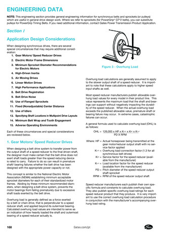
ENGINEERING DATANOTE: This engineering section provides general engineering information for synchronous belts and sprockets (or pulleys)which are useful in general drive design work. Where we refer to sprockets (for PowerGrip GT 2 belts), you can substitutepulleys for PowerGrip Timing Belts. If you need additional information, contact Gates Power Transmission Product Application.Section IApplication Design ConsiderationsWhen designing synchronous drives, there are severalspecial circumstances that may require additional consideration:1. Gear Motors/ Speed Reducer Drives2. Electric Motor Frame Dimensions3. Minimum Sprocket Diameter Recommendationsfor Electric MotorsFigure 3 - Overhung Load4. High-Driven Inertia5. Air Moving DrivesOverhung load calculations are generally assumed to applyto the slower output shaft of a speed reducer. It is important to note that these calculations apply to higher speedinput shafts as well.6. Linear Motion Drives7. High Performance Applications8. Belt Drive Registration9. Belt Drive Noise10. Use of Flanged Sprockets11. Fixed (Nonadjustable) Center Distance12. Use of Idlers13. Specifying Shaft Locations in Multipoint Drive LayoutsMost speed reducer manufacturers publish allowable overhung load values for every model in their product line. Thisvalue represents the maximum load that the shaft and bearings can support without negatively impacting the durability of the speed reducer. When the actual overhung loadexceeds the published allowable value, premature shaft orbearing failure may occur. In extreme cases, catastrophicfailures can occur.14. Minimum Belt Wrap and Tooth EngagementA general formula used to calculate overhung load (OHL) isas follows:15. Adverse Operating EnvironmentsOHL 126,000 x HP x KLCF x KSF x KLLFPD X RPMEach of these circumstances and special considerationsare reviewed below.1. Gear Motors/ Speed Reducer DrivesWhen designing a belt drive system to transfer power fromthe output shaft of a speed reducer to the final driven shaft,the designer must make certain that the belt drive does notexert shaft loads greater than the speed reducing deviceis rated to carry. Failure to do so can result in prematureshaft/ bearing failures whether the belt drive has beendesigned with the appropriate power capacity or not.This concept is similar to the National Electric MotorAssociation (NEMA) establishing minimum acceptablesprocket diameters for each of their standardized motorframes. Abiding by these minimum recommended diameters, when designing a belt drive system, prevents themotor bearings from failing prematurely due to excessiveshaft loads exerted by the belt drive.Overhung load is generally defined as a force exertedby a belt or chain drive, that is perpendicular to a speedreducer shaft, and applied beyond its outermost bearing.Calculated overhung load values are intended to serve asan indication of how heavily loaded the shaft and outermostbearing of a speed reducer actually is.168Where: HP Actual horsepower being transmitted at thegear motor/reducer output shaft with no service factor appliedKLCF Overhung load connection factor (1.3 for allsynchronous belt drives)KSF Service factor for the speed reducer (available from the manufacturer)KLLF Load location factor for the speed reducer(available from the manufacturer)PD Pitch diameter of the speed reducer outputshaft sprocketRPM RPM of the speed reducer output shaftSpeed reducer manufacturers each publish their own specific formula and constants to calculate overhung load.They also publish specific overhung load ratings for eachspeed reducer product that they produce. It is very important to use the correct overhung load calculation procedurein conjunction with the manufacturer’s accompanying overhung load rating.Gates.com/pt
If the calculated overhung load for a particular belt drivesystem does exceed the speed reducer manufacturer’smaximum recommended value, consider altering the beltdrive design. In order to reduce the calculated overhungload, consider:ShaftLengthMin.ShaftDia. Increasing sprocket diameters Reducing belt width Mounting the sprocket closer to the speed reduceroutboard bearingIncreasing the sprocket diameter not only reduces calculated overhung load, it also potentially reduces the requiredbelt width. Reducing the belt width and mounting thesprocket as close as possible to the outermost bearing ofthe speed reducer both move the center of the belt loadcloser to the speed reducer. This also reduces the calculated overhung load. Alterations to the belt drive designshould be made until the calculated overhung load is withinthe speed reducer manufacturer’s recommendations.2. Electric Motor Frame DimensionsMotor dimensions can be important considerationsdepending on the application and its requirements. If motorshaft length, motor shaft diameter, or clearance issues area concern, refer to the motor dimension table on this page.The table lists common general purpose electric motors byframe size.Motor Frame DimensionsFrameSizeShaft Dia. (in)Shaft LengthMin. (in)48561/25/8——3/64 Flat3/16 x 3/16 x 1-3/8143T145T7/87/8223/16 x 3/16 x 1-3/83/16 x 3/16 x 6 x 3/16 x 1-3/81/4 x 1/4 x 1-3/43/16 x 3/16 x 1-3/81/4 x 1/4 x -3/43-1/81/4 x 1/4 x 25/16 x 5/16 x 2-3/81/4 x 1/4 x 25/16 x 5/16 x 43-1/23-3/45/16 x 5/16 x 2-3/43/8 x 3/8 x 2-7/85/16 x 5/16 x 3-3/43/8 x 3/8 x 3-1/26-1/83-1/25-5/83-1/21/21/25/81/21/21/25/81/2x 1/2 x 5x1/2 x 2x 5/8 x 4-1/4x 1/2 x 2x 1/2 x 5x 1/2 x 2x 5/8 x 4-1/4x 1/2 x /41/25/81/23/41/2xxxxxxxx5/8 x 5-1/24 x 2-3/43/4 x 5-5/81/2 x 2-3/45/8 x 5-1/21/2 x 2-3/43/4 x 5-5/81/2 x /85/8Gates.com/ptKey 83169
3. Minimum Sprocket DiameterRecommendations for Electric MotorsMinimum Recommended Sprocket / Sheave DiametersNEMA (The National Electric Manufacturers Association)publishes recommendations for the minimum diameter ofsprockets and sheaves to be used on General PurposeElectric Motors. The purpose of these recommendationsis to prevent the use of excessively small sprockets orsheaves. This can result in motor shaft or bearing damagesince belt pull increases as the diameter is reduced.Table data has been compiled from NEMA Standard MG-114-42; 11/78, MG-1-14-43; 1/68, and a composite of electric motor manufacturers data. Values are generally conservative, and specific motors may permit the use of a smallersprocket or sheave. Consult the motor manufacturer.Motor Frames and Minimum Diametersfor 60 Cycle Electric MotorsHorsepower at Synchronous Speed (rpm)SynchronousBeltsMin.PitchDia. 1/2— �—100——10.810.89.511.91704. High-Driven InertiaMany drives, such as piston compressors, punch presses and crushers, depend on the driveN pulley acting as aflywheel. This flywheel effect, or WR2 is used to help moderate or smooth out fluctuations in driven load and speed.Failure to compensate for this during a redesign can resultin premature damage to the prime mover or early belt failures. This can be a consideration when replacing older beltdrives with new, higher capacity belts.When replacing large pulleys or sheaves with sprockets,be careful not to remove a designed-in flywheel effect. Askquestions of the user to make sure there is not a concernfor a high WR2. If there is a concern, you may have to use awider sprocket, a larger diameter, or a special made-to-order sprocket designed with added weight and WR2.Drives which have a high driveN inertia and are subjected to high acceleration or emergency stop conditionsrequire additional design expertise. Contact Gates PowerTransmission Product Application for further engineeringassistance.5. Air Moving DrivesHVAC Equipment InspectionMany air handling drives have structures that are not particularly rigid, which can create belt tension and drive alignmentproblems resulting in unusual and premature belt wear.Synchronous belts are sensitive to fluctuations in centerdistance that can be caused by inadequate bracketry.Under start up conditions, an AC motor can be required toprovide 150% to 200% of its rated capacity. Synchronousbelts cannot slip, and must transmit the higher start uptorque. Under these conditions, the drive center distancemay collapse if the structure is not sufficiently rigid.With the drive shut off and safely locked out, a simplemethod to use when inspecting potential drive conversionsis to grab the two belt spans and push them together whileobserving the motor. If any significant relative change incenter distance or motor position is noticed, the drive’sstructural strength is most likely insufficient for a simpleconversion. The structure would need to be reinforcedto obtain optimum performance from a synchronous beltdrive. The best conversion candidates have motors thatare mounted solidly on support bracketry that is part of thefan’s structural system. When possible, select synchronous drives with diameters similar to existing V-belt sheavediameters. This will maintain similar belt pulls and loads onthe shafts and structure.Air Handling Unit Start-Up CharacteristicsFull Load Start UpStart up loads can be a concern when evaluating potentialdrives for conversion to synchronous belts. Synchronousbelts will transmit all of the start up torque, where V-beltsmay slip if the load is excessive. Due to the inertia of thefan, start up loads can potentially be 150% to 200% of thenormal operating load. It is important that the start up loadbe considered by selecting appropriate service factorswhen designing a belt drive system.Gates.com/pt
Controlled Start UpAn air handling drive with soft start or variable frequencycontroller (AC Inverter) is ideal for conversion to synchronous belts. The fan will be ramped up to speed slowly,with a corresponding increase in load as the speed increases. Structural flexing is typically not a concern whendesigning synchronous belt drives on systems using softstarts or variable frequency controllers.Fan SpeedThe volume of air being transmitted and the requiredhorsepower are both sensitive to changes in the driveN fanspeed. If designing a synchronous belt drive for energysavings, it is important that the synchronous belt drive bedesigned to operate at the proper driveN fan speed. Allconversions from existing V-belt drives should have thesynchronous belt drive speed ratio based on a measureddriveN shaft RPM, and not calculated from the theoreticalV-belt speed ratio. This measurement can be made byeither using a mechanical contact tachometer or a strobetachometer.The horsepower requirement for fans varies with the cubeof the fan speed. A small change in the fan speed makes amuch larger difference in the actual horsepower and energyrequired.HP1/HP2 (RPM1/RPM2)3Where: HP1HP2RPM1RPM2 Initial HorsepowerNew Horsepower @ New Fan RPMInitial Fan RPMNew Fan RPMMaintenance and Safety Manual (Form 14995) fordetailed information about proper belt drive alignment.Proper belt pre-tension is necessary to obtain optimum beltperformance. This is particularly true for the high inertiastart up loads seen in ACHE applications. If belt installationtension is too low, V-belts will be prone to slippage andsynchronous belts will be prone to tooth jump or ratcheting.Motor controllers are sometimes used to bring the fan up tospeed slowly (soft start), decreasing the chance of synchronous belt ratcheting.6. Linear Motion DrivesIn linear motion drives, such as a rack and pinion application,the belt is not transmitting a load in the conventional rotational manner. The two cut ends of the belt are connectedto clamping fixtures and the belt travels back and forth aspecified distance while rotating over a sprocket. Because ofthese characteristics, the drive design process will typicallynot follow standard catalog design procedures.The designer will most likely have available a maximum beltload or pull which will need to be related to the belt’s allowable working tension. Reasonably sized sprocket diametersare still required to prevent excessive stress fatigue in thebelt. In these applications, the designer may either use endless belts and cut them, or use standard long length beltingwhen available. Product listings are on pages 115-117. GatesPower Transmission Product Application may be consultedfor design assistance.7. High Performance Vehicle ApplicationsAir-Cooled Heat Exchanger (ACHE) ApplicationsAir-coole
tric motor manufacturers data. Values are generally conser-vative, and specific motors may permit the use of a smaller sprocket or sheave. Consult the motor manufacturer. 4. High-Driven Inertia Many drives, such as piston compressors, punch press-es and crushers, depend on the driveN pulley acting as a flywheel. This flywheel effect, or WR 2 is used to help mod-erate or smooth out fluctuations .