Transcription
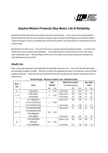
Applied Motion Products Step Motor Life & ReliabilityApplied Motion Products step motors are brushless motors with excellent bearings.As such, they can have a phenomenal life.Factors that determine motor life include: bearing life, insulation system temperature, shaft strength, and environmental conditions.The goal of this paper is to help you understand these, avoid motor life problems, and provide solutions if a standard motor does notmeet your needs.Most life factors are rated in hours.This is the time the motor is actually running at its operating temperature.As a guide, life of20,000 hours running is suitable for many applications. This typically represents 10 years of field use (8 hours / day, 5 days /week, and 50 weeks / year).With good design motor life can be much longer; once the actual working cycle, shaft loads, andmotor temperatures are accounted for.Shaft Life:When a motor shaft is subjected to large radial loads it can break after many hours of use. This is due to the radial load causingthe shaft material to fatigue as it rotates.material and shaft size.Shaft life is a function of the magnitude and location of the radial load, as well as the shaftAs the radial load is moved further from the motor mounting face, the maximum radial force the shaft canwithstand drops.Shaft Strength - Maximum Radial Load - Standard ShaftsMotorSize811, adial Force LocationMax. RadialDiameterFrom Motor MountingForcemmInch40.15750.19723, 2434InchNLbs.End of shaft200.79184Center of Flat16.50.65306.7End of shaft240.94214.7Center of Flat16.50.65306.7HT17-275/276/277/278End of shaft240.94214.7HT23-560/593/594/595Center of Flat13.10.526213.9HW23-598/601End of shaft20.60.81449.9HT34-504/505/506Center of Key20.80.8230067End of 06HT34-495/496/49756.3512.70.1970.250.50
A common cause for shaft (and bearing) failure, is high radial loads that arecreated when a pulley is attached to the motor shaft at a large distance fromthe motor mounting face, and the belt has high tension.To avoid thiscondition mount pulleys and gears as close to the face of the motor aspossible, and avoid over tightening belts.This dramatically reduces theshaft stress, and increases the life of the bearings.Bearing Life:Bearing life depends on several factors including: axial and radial loads, motor speed, temperature, and the bearing ratings.Because the front bearing is positioned closest to the motor shaft, it usually carries a higher load and has the shortest life.There are two sets of bearing life curves below. The first set shows the maximum axial and radial shaft loads for 20,000 hours L10bearing life at various speeds. These curves are for the radial load applied at the distance from the mounting face shown on thecurve (usually the center of the flat / keyway). These curves are for the shortest motor in the series.Longer motors have asomewhat higher rating.Additional life curves are shown for larger motors, (size 17, 23, 34, 42) They show bearing life, at various speeds and radial loads.These curves are for the radial load applied at the distance from the mounting face shown on the curve (usually the center of the flat/ keyway).Each page has six graphs for one motor size and length. There are multiple graphs for different axial loads, andseparate graphs for English and metric units.Another limiting factor for bearing life can be the bearing grease life.grease.Applied Motion Products uses special high-grade bearingNormally Applied Motion Products motors operate for years without the grease being an issue.Typical grease life is40,000 hours of operation.Insulation Life:Applied Motion Products standard insulation is class B, rated for 130 C. By industry definition, insulation life is rated for 20,000hours, at rated temperature. For every 10 C temperature reduction, insulation life approximately doubles.If the motor internaltemperature is actually running at 120 C insulation life is 40,000 hours; at 110 C the life is 80,000 hours, etc. Because it’s rare forApplied Motion Products motors to be operated so that internal motor temperatures are continuously above 90 C, insulation life isusually not a limiting factor.Insulation and bearing temperature can be confirmed in the application by measuring the surface temperature of the motor, afterrunning the machine under worse case conditions for several hours. The maximum internal temperature is about 15 C hotter thanthe surface temperature of the motor. Thus, maximum temperature equals the measured motor body temperature, plus 15 C, plusthe difference between the maximum rated machine ambient and the test ambient.
MTBF - Mean Time Between Failures:MTBF is a number that represents failure rate.It is combined with other component MTBF numbers to estimate the reliability of asystem. The method for estimating reliability is defined in MILITARY HANDBOOK MIL-HDBK217F (notice 2).For motors, MTBF is mostly influenced by the bearing and insulation life. The factors included in the MTBF calculations are operatingmotor temperature, and the motor design life. Most applications for step motors fall into one of two different situations.Typical Commercial:The motor is actually operated at infrequent at random times throughout the day. Examples of this type ofapplication include: 3 D printers, antenna positioning, solar systems, ATM machines, vending machines, andperformance lighting.Typical Industrial:The motor is used for production equipment and operates a high percentage of the time throughout the workday. Examples of this type of application include: production equipment, medical analysis equipment used incommercial laboratories, packaging equipment, and industrial robots.ApplicationTypical IndustrialTypical Commercial10 years, 1 shift5 years 24/7High duty cycleLow duty cycleHours20,00043,800 C6545Hours406,5001,123,600per 1,000,000 Hours3.441.21Operating ConditionsLC design lifeTA Motor TemperatureMTBFlp Failure RateOther Life Factors:Other application specific conditions that can lead to early motor failure include: The presence of water or humidity that causes corrosion inside the motor. This can then bind the rotor or damage thebearings.Applied Motion Products anti-rust treatment can eliminate this problem. Dust that may get inside the motor and cause binding or damage the bearings.Sealed motors and shaft seals are available from Applied Motion Products. High shock and vibration can cause a variety of failures.Larger bearings, magnet wire lead loops, & varnished windings can all be solutions. High shaft loads or longer life may be required. Excessive temperatures may be present, and shorten the life of the insulation or bearing grease.Applied Motion Products can supply motors with over size bearings and shafts to meet your needs.Low temperature rise motors are available from Applied Motion Products.Applied Motion Products also has encapsulated motor designs that can be especially effective for solving many of theseproblems. If you want assistance with your motor application, please contact Applied Motion Products. We can help with analysis ofyour application, and recommendations for your specific needs.
Maximum Shaft Loads for: 20,000 Hour L10 Bearing Life
Maximum Shaft Loads for: 20,000 Hour L10 Bearing Life
Maximum Shaft Loads for: 20,000 Hour L10 Bearing Life
HT17-268/269/270 - Bearing Life
HT17-271/272/273/274 – Bearing Life
HT17-275/276/277/278 – Bearing Life
HT23-560/593/594/595 – Bearing Life
HT23-559/596/597/598, HW23-598 – Bearing Life
HT23-599/600/601, HW23-601 – Bearing Life
HT34-504 – Bearing Life
HT34-505 – Bearing Life
HT34-506, HW34-506 – Bearing Life
Microsoft Word - AMP Step Motor Life data Author: leo86 Created Date: 11/8/2017 9:34:30 AM .