Transcription
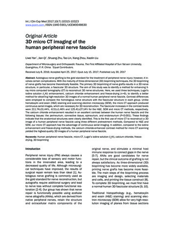
Int J Clin Exp Med 2017;10(7):10315-10323www.ijcem.com /ISSN:1940-5901/IJCEM0048630Original Article3D micro CT imaging of thehuman peripheral nerve fascicleLiwei Yan*, Jian Qi*, Shuang Zhu, Tao Lin, Xiang Zhou, Xiaolin LiuDepartment of Microsurgery and Orthopaedic Trauma, The First Affiliated Hospital of Sun Yat-sen University,Guangzhou, P. R. China. *Equal Contributors.Received July 8, 2016; Accepted April 25, 2017; Epub July 15, 2017; Published July 30, 2017Abstract: Autologous nerve grafting is the gold standard for the treatment of peripheral nerve injury; however, it involves certain complications. With the maturity of three-dimensional (3D) bioprinting techniques, the 3D bioprintingof nerve grafts has become theoretically feasible. The primary 3D bioprinting of nerve grafts results in a 3D nervestructure, in particular, a fascicular 3D structure. The aim of this study was to identify a method for enhancing Xray micro computed tomography (CT) to reconstruct 3D nerve structures. Here, we used three techniques, Lugol’siodine solution (I2KI) enhancement, calcium chloride enhancement and freeze-drying (n 6), to identify a bettermethod for obtaining high-resolution 3D images of a normal human peripheral nerve fascicle. Contrast differenceswere employed to compare the homologous nerve structure with the fascicular structure in each group. Unlikehematoxylin and eosin (H&E) staining and scanning electron microscopy (SEM), the micro CT approach producedcontinuous serial images, which are necessary for 3D reconstruction. The fascicular increases in the contrast levelswere 211.74 31.44%, -6.51 1.46% and 125.41 27.14% for the H&E, SEM and micro CT methods, respectively.The calcium chloride enhancement resulted in an excellent contrast between the human nerve fascicle and thefollowing tissues: the perineurium, connective tissue, epineurium, and endoneurium (p 0.001). These findingsindicate that the anatomical structures were clearly identified. This is the first use of micro CT to reconstruct a 3Dimage of a human peripheral nerve fascicle using three different pretreatment methods. Compared to H&E andSEM, our micro CT approach has the advantage of continuous serial imaging. In addition, compared to the iodineenhancement and freeze-drying methods, the calcium chloride-enhanced contrast method for micro CT scanningyielded the highest-quality 3D images of a human peripheral nerve fascicle.Keywords: Human peripheral nerve fascicle, micro CT, Lugol’s iodine solution (I2KI), calcium chloride, freezedrying, 3D bioprintingIntroductionPeripheral nerve injury (PNI) always causes aconsiderable loss of sensory and motor functions in the innervated area, leading to adecreased quality of life. Although microsurgical techniques have improved, the results ofsurgical repair remain less than ideal [1]. Autologous nerve grafting is commonly used asthe gold standard for nerve reconstruction, butautografts require additional surgery and leadto nerve loss without complete functional restoration [2-4]. Our group has shown that nerverepair is functionally possible using acellularnerve allografts (ANAs), which are derived fromnative peripheral nerves, retain the structureand extracellular matrix components of theoriginal nerve, and stimulate a minimal hostimmune response to connect gaps in the nerve[5-7]. ANAs are good candidates for nerverepair, but the clinical outcome of grafting is notalways satisfactory. As three-dimensional (3D)bioprinting has become more widely available,printing nerve grafts has become more feasible. The main steps of the bioprinting processare imaging and design, selecting materialsand cells, and printing the tissue construct [8].To complete 3D bioprinting, we must first havea normal human 3D fascicular structure [9, 10].Traditional histopathology (e.g., hematoxylinand eosin (H&E) staining) and scanning electron microscopy (SEM) allow for very high-resolution imaging of planes from tissue sections
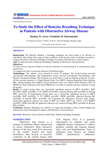
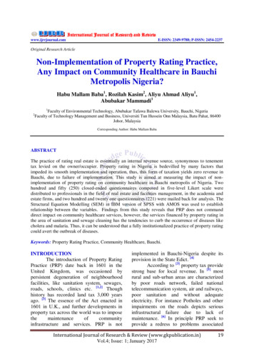
3D micro CT of the nerve fascicleFigure 1. A: A 23-cm-long, fresh human tibial nerve from the lower limb of an amputation patient. B: The nerve wasdivided into 5 portions, each of which was 4 cm long. Segments 1, 2, and 3 were pretreated for micro CT with Lugol’siodine solution (I2KI), calcium chloride, and freeze-drying, respectively. Segment 4 was pretreated for H&E staining,and segment 5 was pretreated for SEM.using specific staining methods. However, these methods are destructive and can only beused for two-dimensional (2D) imaging. A 3Dimage is difficult to obtain with these approaches because the sectioning and mounting processes often result in geometric nerve distortion. In addition, the staining process is timeconsuming and labor intensive. X-ray microcomputed tomography (micro CT) can be usedfor the non-destructive analyses of tissue specimens. Micro CT was first introduced in the1980s by Elliotthe and Dorer and uses X-rayattenuation data acquired from multiple projection angles to produce high-resolution images.Micro CT uses X-rays to produce image filesthat can be compiled to generate 3D images[11]. Micro CT has non-destructive and reconstructive characteristics and can be used toanalyze 3D tissue structures, particularly mineralized tissue, such as bone, teeth and cartilage [12-15]. Although micro CT is already anestablished technology for imaging different types of mineralized tissues, such as bone andteeth, soft-tissue applications of micro CT imaging in comparative morphology have been limited by low intrinsic X-ray contrast, particularlyin peripheral nerves. With the use of certaincontrast staining methods, micro CT can produce high-quality, high-resolution images of soft tissues [16]. Micro CT can be used to visualize fine soft-tissue details in embryos and invertebrates by increasing the differential attenuation of the X-rays [17, 18].10316Thus, we investigated the use of 3D micro CTfor the non-invasive characterization of thehuman fascicle. The aim of this study was todetermine whether treating human peripheralnerve tissue with a micro CT contrast agent(i.e., Lugol’s iodine solution (I2KI), calcium chloride or freeze-drying) can yield images with useful anatomical contrast compared to those obtained by H&E staining and SEM. In addition,we wanted to evaluate the most effective methods for micro CT scanning.Materials and methodsHuman nervesFor this study, we used human tibial nerves excised from the lower limbs of amputation patients at The First Affiliated Hospital of Sun Yatsen University. Each tibial nerve was 23 cm inlength. External debris such as muscle and fatwas removed. Fresh nerves were divided into 5parts, each of which was 4 cm long, taking intoconsideration the elastic quality of fresh nerves(Figure 1). The fresh nerves were immediatelyfixed with 4% paraformaldehyde at room temperature for 4 hours and underwent the corresponding treatments for micro CT, H&E or SEM.All procedures were performed with informedconsent and were approved by the institutionalreview boards of the contributing institutionsof The First Affiliated Hospital of Sun Yat-senInt J Clin Exp Med 2017;10(7):10315-10323
3D micro CT of the nerve fascicleUniversity, in accordance with the Declarationof Helsinki.Micro CT scanning and specimen fixation andstainingAll of the nerves were imaged with a micro CTsystem (Micro CT 80 SCANCO Medical, Basserdorf, Switzerland). The nerves were preparedfor their respective methods and placed in asample holder for imaging. A sagittal scoutimage, comparable to a conventional planarX-ray, was obtained to define the starting andending points for the acquisition of a series ofcoronal slices through the nerve. The nerveswere imaged with foam, which does not blockX-rays, as the background medium. Imageswere generated by operating the X-ray tubeat a voltage of 55 kVp and a current of 72 μA.The total acquisition time was 36 min per sample, and 216 slices were obtained for eachscan. Images were obtained at an isotropic resolution of 5 μm for the nerve scan.Lugol’s iodine solution (I2KI) enhancementmethodFresh nerves were immersed in 4% paraformaldehyde for approximately 12 hours. In theiodine-enhancing process, the nerves were firstremoved from the 4% paraformaldehyde solution and then washed in distilled water for 4hours at room temperature. The nerves werethen immersed in Lugol’s iodine solution (Sigma-Aldrich, St. Louis, USA) diluted to 50% using distilled water and shocked (oscillation frequency of 120 GHz per hour) for 24 hours.Finally, filter paper was used to absorb waterfrom the nerve surfaces in preparation forscanning.Calcium chloride enhancement methodFresh nerves were immersed in 4% paraformaldehyde for approximately 12 hours. The firststep of the calcium chloride enhancement process was similar to that of the iodine enhancement process. Subsequently, the nerves wereimmersed in a saturated calcium chloride (Sigma-Aldrich, USA) solution (CaCl2 in distilledwater with no visible material at the bottom)and shocked for 24 hours (oscillation frequency of 120 GHz per hour). The final step of thisprocess was similar to that of the iodine enhancement process.10317Freeze-drying methodFresh nerves were immersed in 4% paraformaldehyde for approximately 12 hours. The firststep of the freeze-drying process was similar tothat of the iodine enhancement process. Thenerves were then immersed in liquid nitrogenand placed in a lyophilizer for 7 days to removewater molecules.H&E stainingFor histological analysis, nerves were fixed in4% paraformaldehyde for 2 hours, followed byseveral washes in phosphate-buffered saline(PBS) for 24 hours. The fixed nerves were dehydrated by a graded series of ethanol, embedded in paraffin wax, sectioned to a thickness of8 μm, and mounted on microscope slides. Sections were stained with H&E to visualize thetransverse structure of the nerves.SEMNerves were fixed in 4% paraformaldehyde for2 hours, washed in PBS for 24 hours and snapfrozen by immersion in liquid nitrogen. The fixednerves were dehydrated by a graded series ofethanol (10 to 100%), followed by critical-pointdrying with CO2. After the samples were mounted with carbon cement and sputter-coated with an approximately 10-nm-thick gold film, theywere examined by SEM (FEI QUANTA 200, Netherlands) using a lens detector with a 5-kV acceleration voltage at calibrated magnifications.Transverse sections of the nerve segmentswere analyzed.Quantification of the nerve brightness andcontrast levelsTo test which method yielded the greatest levels of contrast between fascicular and connective tissue via micro CT imaging, we quantifiedthe pixel brightness using grayscale values(GVs) from 0 (black) to 255 (white). First, weused a DICOM viewer (SANTE DICOM Viewer,Germany) to convert the DICOM images to TIFFimages, removing all background media (i.e., foam) from the single-slice TIFF images. Second,the resultant image files containing only nerveinformation were opened in Adobe Photoshop(Adobe Systems, Mountain View, CA, USA) tomeasure the pixel brightness. Specifically, themean GV standard deviation (SD) for eachInt J Clin Exp Med 2017;10(7):10315-10323
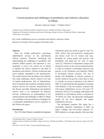
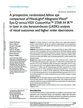
3D micro CT of the nerve fascicleFigure 2. The three methods yielded images generally comparable with those obtained by H&E and SEM. Micro CTyields continuous serial images, while H&E and SEM only yield intermittent images.5 5 pixel square sampled within the anatomical structures was obtained using the histogram tool in Adobe Photoshop for each completemicro CT TIFF image. Adobe Photoshop automatically calculated the mean GV and corresponding SD for each square of sampled pixels. Todetermine the characteristic GV for each method, the mean values of all pixel samples of thehomologous nerve under the same stainingregime were averaged. Pooled SDs for thesemeans were then calculated by squaring eachSD to derive the variance, averaging the variances for similar tissues at similar stainingdurations, and taking the square root of thoseaveraged variances [19]. Finally, the contrastlevel of each method was determined using the- Xmean , where C is thefollowing equation: C XtXmeancontrast difference as a percentage, Xt is themean GV of the structure for a given nerve, andXmean is the mean GV for the entire TIFF slice.Contrast difference is a unitless measure and10318is represented here as a percentage value compared to the mean brightness of the entire corresponding TIFF image. Positive values werebrighter than the mean, and negative valueswere darker. Comparing contrast levels in thisway allowed us to determine whether certaintissues are more clearly visualized under certain preparation regimes. No adjustments weremade to the brightness or contrast levels of thefrontal-view TIFF images prior to taking thesemeasurements.Statistical analysisAll of the numerical data are presented as themeans and SDs. Student’s t-test was used totest the statistical significance of differencesbetween sample means. All of the results weresubjected to statistical analysis using SPSSv11.5 software for Windows (student version).Statistically significant values were defined asp 0.01.Int J Clin Exp Med 2017;10(7):10315-10323
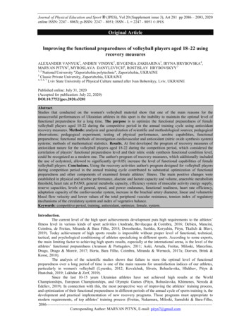
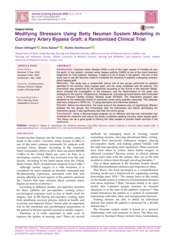
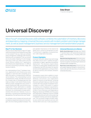
3D micro CT of the nerve fascicleFigure 3. 2D coronal sections of 3D micro CT images of normal human nerves treated by different methods. Fromleft to right, the contrast is enhanced by (A) Lugol’s iodine solution (I2KI); (B) Calcium chloride; and (C) freeze-drying.There is no native micro CT scan of the normal nerve without a pretreatment. (A) The iodine enhancement methodyielded the highest-quality images of the connective tissue and fascicle; (B) The calcium chloride enhancementmethod produced the highest-quality images of the perineurium, connective tissue and fascicle; and (C) the freezedrying method damaged the perineurium structure.3D reconstructionThe gross anatomical structures of the normalhuman nerve, including the epineurium, connective tissue, perineurium, and fascicle, werereconstructed digit
used a DICOM viewer (SANTE DICOM Viewer, Germany) to convert the DICOM images to TIFF images, removing all background media (i.e., fo-am) from the single-slice TIFF images. Second, the resultant image files containing only nerve information were opened in Adobe Photoshop (Adobe Systems, Mountain View, CA, USA) to measure the pixel brightness. Specifically, the mean GV