Transcription
High-Resolution 3D AcousticBoreholeIntegrity Monitoring SystemProject Number: FWP-FE-855-17-FY17Cristian PanteaLos Alamos National LaboratoryU.S. Department of EnergyNational Energy Technology LaboratoryMastering the Subsurface Through Technology Innovation, Partnerships and Collaboration:Carbon Storage and Oil and Natural Gas Technologies Review MeetingAugust 13-16, 2018
Partners/CollaboratorsCristian Pantea1, Eric S. Davis1,2, Dipen N. Sinha1, Craig Chavez1, Vamshi Chillara1,Bill Carey1,Yu Chen1, Lianjie Huang1,Barbara Kutchko3, Dustin Crandall3, Roger Chen4,Douglas A. Blankenship5, Jiann-Cherng Su5,Hector J. Santos-Villalobos6, Yarom Polsky6, Roger Kisner61LosAlamos National Laboratory, Los Alamos, NM 87545of Houston, Department of Physics, Houston, TX 772043National Energy Technology Laboratory, Pittsburgh, PA 152364West Virginia University, Department of Civil and Environmental Engineering, Morgantown, WV 265065Sandia National Laboratories, Albuquerque, NM 871856Oak Ridge National Laboratory, Oak Ridge, TN 378312University2
Presentation Outline Technical StatusAccomplishments to DateLessons LearnedSynergy OpportunitiesProject Summary3
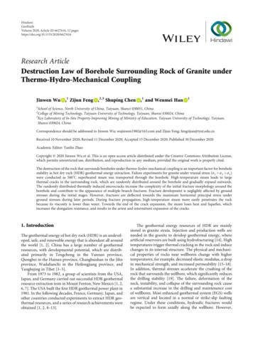
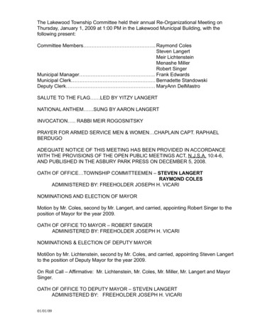
Technical StatusDevelop a high-resolution 3D imaging system for improvedwellbore diagnostics and integrity assessmentExisting ultrasonic tools workwell for casing inspectionExtend applicability to: (1) casing-cement interface, (2)cement-formation interface, and (3) out in the formation(up to 3 meters).Performed a comprehensive literature/existing technology studyfor wellbore integrity monitoring tools.Comparison of existing techniques and the present Sonic probe0.3-815 300Present approach10-150 3 5Ultrasonic probe 250casing4-5* Picture from S.E. Gasda, Environ Geol (2004) 46: 707-7204
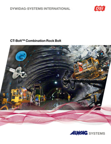
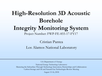
Technical StatusThe Proposed Approach:Novel technique that fills this technology gap.1. Collimated beam for increased resolution2. Low frequency for deeper penetrationAttenuation fnf frequency, n 1-2Low frequencydeep penetration Conventionallow-frequencytransducerbeam profileCollimatedbeamHigh frequencylimited penetrationTransducer5
Technical StatusMulti-lab projectInter-lab collaboration and teamingarrangements/partnerships LANL: Develop acoustic source, imaging system, and image processing. NETL: Investigate acoustic metrics for foamed cements. Incorporate newmetrics for wellbores in the field. ORNL: Explore different image processing approaches. SNL: Perform experiments in more realistic boreholes. Incorporate data fromrealistic borehole and compare resolution with lab experiments.6
Technical StatusFoamed Cement Young’s Modulus PredictionA material model has been developed to compute the degree of hydration of Class H cementThe early-age Young’s Modulus of the Neat Class H Cement was measured using the Ultrasonic Pulse Velocity (UPV)method.The material model was used to calculate the Young’s modulus of the neat Class H cement.The effective medium theory is the basis for the calculation of the Young’s modulus which assumes the cement paste is aporous medium consisting of hydration products (C-S-H gel), pores, pore water and anhydrous cement.Young’s Modulus of Neat (0%) Class H Cement Comparison (w/c 0.38)Effect of w/c ratio on Young’s Modulus of Neat Class H Cement7
Technical StatusComparison of analytical and experimentallyobtained out-of-plane displacement patterns ofthe radial modesPaper recently submittedComparison of analytical andexperimentally obtained beam profiles fromthe radial modes8
Technical StatusEffect of radial clampingon beam profileUltrasonic beam profiles in water generated by RM-3 at 161.8 kHzfor different lateral stiffness kNormalized out-of-plane displacement on the surface of thedisc for RM-3 for different lateral stiffness k (N/m3)Wave Motion, vol. 76, (2018), pp. 19-27andProceedings of SPIE, vol. 10170, (2017), Article no. 10170249
Technical StatusBeam profile in water for the 3rd radial mode RM-3; freetransducer (left) and clamped transducer (right)Appl. Phys. Lett., vol. 110, issue 6, (2017), 06410110
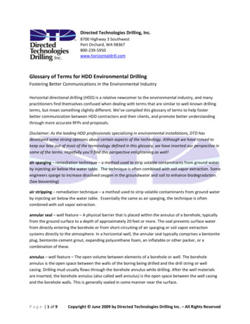
Technical StatusExperimental concrete barrel with LANL’s 3D imaging prototype in a boreholelocated at the center of the concrete barrel(a) Velocity model based on experimental data; (b) Initial velocity model usedfor full-waveform inversion; (c-e) Results of full-waveform inversion obtainedusing the center frequencies of 29 kHz (c), 42 kHz (d), and 58 kHz (e).Appl. Phys. Lett., vol. 113, issue 7, (2018) – in printLeast-squares reverse-timemigration image obtainedusing synthetic ultrasonicdata and the velocity modelof full-waveform inversion11
Technical StatusLowering the imaging systemin a 4” wellboreDrawing of front face ofclamped transducerIllustration of beampropagation in formation12
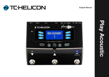
Technical StatusPerformed quick scans on granite blocks360 deg rotation, and 475 mm vertical span15 deg and 25 mm step size13
Accomplishments to Date– Performed a comprehensive literature/existing technology studyfor wellbore integrity monitoring tools– Identified potential partner for further developing the proposedtechnique– Refined hardware (ACCObeam – Acoustic Collimated beam)– Refined software for faster measurement and analysis– Performed theoretical prediction on foamed cement Young’smodulus with different hydration degrees– Started acquiring data in granite with embedded defects (wallthinning, casing eccentricity, channeling, delamination)14
Lessons Learned– Research gaps/challenges. Small issues with hardware packaging for experiments in granite– Unanticipated research difficulties. N/A– Technical disappointments. N/A– Changes that should be made next time. Closer interaction with technical members of the team15
Synergy OpportunitiesPossible future collaboration identified in several different areas of interest to the CO2 sequestration/FEcommunity: Hydraulic Fracturing/Simulation Diagnostics, Intelligent Monitoring Systems/Integration, AssociatedCO2 Storage, Well Integrity and Zonal Isolation, Geophysics for CO2 Storage, Oil and Gas Fundamental Science,Geomechanics for CO2 Storage, Wellbore Integrity and Mitigation, etc.For this session, “Well Integrity and Zonal Isolation”:–Nonlinear Acoustic Methods for the Detection and Monitoring of CO2/Brine Leakage Pathways in WellboreSystems - Los Alamos National Laboratory- Carly Donahue (Rice) –Embedded Sensor Technology Suite for Wellbore Integrity Monitoring - National Energy TechnologyLaboratory - Paul Ohodnicki (Albenze) –Combination of linear acoustic/imaging data with nonlinear acoustics can lead to complementary information for bettercharacterization of leakage pathways in wellbore systems.Embedding a system of low-frequency collimated beam transmitter-receiver can help in identification of certain types ofdefects. Improved investigation range and lateral resolution are the key advantages of our imaging system.Autonomous Monitoring of Wellbore Integrity Applying Time Reverse Nonlinear Elastic Wave Spectroscopy(TR NEWS) and Fiber Optic Sensing and Communication – LANL - Paul Johnson (Rice) Complementary information can be obtained, with improved range and resolution. That implies additional adaptation forintegration of our system in an autonomous system.16
Project Summary– Key Findings: There are no commercial acoustic sources that provide a collimated beamover a frequency range of 10–250 kHz in a small package that works indifferent media Developed robust operation software, speeding up data collections to afactor of at least 10 times Developed improved acoustic source, significantly more powerful than itspredecessor (which was based on nonlinear acoustics)– Next Steps: Further refine acoustic source for deeper penetrationEnhance receivers sensitivityImage processing and technique refinement for faster collection/analysisEnhance capabilities for foamed cements17
Publications–––––Appl. Phys. Lett., 2018, v. 113, issue 7, p. 071903Wave Motion, 2018, vol. 76, p. 19-27Appl. Phys. Lett., 2017, v. 110, issue 6, p. 064101Proceedings of SPIE, 2017, v. 10170, p. 10170241 manuscript in preparation (sandstone characterization)– 1 conference paper in print – Rock Mechanics– 1 conference paper submitted – Nondestructive Evaluation– 1 non-provisional patent (Resonance-based Nonlinear Source)– 1 non-provisional patent (Bessel-like Acoustic Source)– 1 provisional patent (Imaging Technique with Low-frequency Beam)18
Appendix– These slides will not be discussed during the presentation, butare mandatory.19
Benefit to the Program Program goals being addressed:– Develop and validate technologies to ensure 99 percentstorage permanence.– Develop technologies to improve reservoir storage efficiencywhile ensuring containment effectiveness. Project benefits statement:The research project is developing a Borehole IntegrityMonitoring System to reduce the risk of release of CO2 aroundthe well casing and cement. The technology, when successfullydemonstrated, will provide an improvement over currentwellbore diagnostics and integrity assessment techniques. Thistechnology contributes to the Carbon Storage Program’s effortof improving reservoir storage efficiency while ensuringcontainment effectiveness.20
Project OverviewGoals and Objectives Project goals and objectives in the Statement of Project Objectives.– The main objective of this project is to develop a high-resolution3D imaging system for improved wellbore diagnostics and integrityassessment, with the ultimate goal to develop a commerciallydeployable technology.– Wellbore integrity monitoring and characterization of the nearwellbore environment are in need of novel technologies for better,faster and safer characterization methods. Some of the goals ofthese methods are: (1) improved resolution, (2) extendedcharacterization range, and (3) in-situ/real-time monitoring. We areplanning to work in parallel to address all these three requirements,such that we can provide a complete solution for wellborediagnostics and integrity assessment.21
Project OverviewGoals and Objectives Project goals and objectives in the Statement of ProjectObjectives.– How the project goals and objectives relate to the programgoals and objectives: We are looking into providing a complete solution for wellborediagnostics and integrity assessment. As mentioned on a previousslide, this technology contributes to the Carbon Storage Program’seffort of improving reservoir storage efficiency while ensuringcontainment effectiveness.22
Project OverviewGoals and Objectives Project goals and objectives in the Statement of Project Objectives.– Identify the success criteria for determining if a goal or objectivehas been met: Identified and assessed existing commercial technology. Determined resolution for channeling outside casing. Performed successful tests on wellbores with foamed cements, withsimilar resolution as for neat cements. Progress toward tool ruggedization for work in adverse conditions. Demonstrated progress toward experimental technique and imageprocessing refinement. Improved detection range through foamed cements (these are moreattenuating than neat cements). Final success metrics : Prototype in field functionality similar to theone observed in tests in the laboratory.23
Organization Chart Describe project team, organization, and participants.– LANL: Develop acoustic source, imaging system, and imageprocessing.– NETL: Investigate acoustic metrics for foamed cements.Incorporate new metrics for wellbores in the field.– ORNL: Explore different image processing approaches.– SNL: Perform experiments in more realistic boreholes.Incorporate data from realistic borehole and compareresolution with lab experiments.24
Gantt ChartGo/No-Go1 (end Q2Y1)Tabulate commercial 3D imaging techniques for boreholeintegrity- no commercial technologies for high-res 3D imagingtechnology with similar depth of penetration ( 3 m) andresolution ( 5 mm)Go/NoGo2 (end Y1)Detect defects at the cement-formation interface, withhigh resolution- defects detection at the cement-formationinterface with a resolution of at least 5 mmGo/No-Go3 (end Y2)Tool survival in adverse conditions of corrosiveness, hightemperature and high pressure (brines, 250 C, 45 kpsi)- imaging system can survive in adverse conditions oftemperature, pressure and corrosivenessGo/No-Go4 (end Y2)Imaging capabilities out in the formation, up to 3 meters- defects/features (up to 3m) can be resolved in thereceived signalLegend shaded areas:CompletedIn works25
BibliographyPeer reviewed publications generated from the project:– Chen, Y., Gao, K., Davis, E.S., Sinha, D.N., Pantea, C., and Huang, L., 2018, Full-waveforminversion and least-squares reverse-time migration imaging of collimated ultrasonic-beam data forhigh-resolution wellbore integrity monitoring. Appl. Phys. Lett., v. 113, issue 7, p. -, available at:aip.scitation.org in print– Chillara, V.K., Pantea, C., and Sinha, D.N., 2018, Radial modes of laterally stiffened piezoelectricdisc transducers for ultrasonic collimated beam generation. Wave Motion, vol. 76, p. 19-27,available at: 517300938– Chillara, V.K., Pantea, C., and Sinha, D.N., 2017, Low-frequency ultrasonic Bessel-like collimatedbeam generation from radial modes of piezoelectric transducers. Appl. Phys. Lett., v. 110, issue 6,p. 064101, available at: aip.scitation.org/doi/10.1063/1.4975800– Chillara, V.K., Pantea, C., and Sinha, D.N., 2017, Coupled electromechanical modeling ofpiezoelectric disc transducers for low-frequency ultrasonic collimated beam generation.Proceedings of SPIE, v. 10170, p. 1017024, available /12.226219526
Storage, Well Integrity and Zonal Isolation, Geophysics for CO. 2. Storage, Oil and Gas Fundamental Science, Geomechanics for CO. 2. Storage, Wellbore Integrity and Mitigation, etc. For this session, "Well Integrity and Zonal Isolation": - Nonlinear Acoustic Methods for the Detection and Monitoring of CO. 2 /Brine Leakage Pathways in Wellbore