Transcription
HindawiGeofluidsVolume 2020, Article ID 6627616, 12 pageshttps://doi.org/10.1155/2020/6627616Research ArticleDestruction Law of Borehole Surrounding Rock of Granite underThermo-Hydro-Mechanical CouplingJinwen Wu ,1 Zijun Feng ,2,3 Shuping Chen ,1 and Wenmei Han11School of Science, North University of China, Taiyuan, Shanxi 030051, ChinaCollege of Mining Technology, Taiyuan University of Technology, Taiyuan, Shanxi 030024, China3Key Laboratory of In-Situ Property-Improving Mining of Ministry of Education, Taiyuan University of Technology, Taiyuan,Shanxi 030024, China2Correspondence should be addressed to Jinwen Wu; wujinwen1982@163.com and Zijun Feng; fengzijun@tyut.edu.cnReceived 10 November 2020; Revised 11 December 2020; Accepted 15 December 2020; Published 30 December 2020Academic Editor: Yanlin ZhaoCopyright 2020 Jinwen Wu et al. This is an open access article distributed under the Creative Commons Attribution License,which permits unrestricted use, distribution, and reproduction in any medium, provided the original work is properly cited.The destruction of the rock that surrounds boreholes under thermo-hydro-mechanical coupling is an important factor for boreholestability in hot dry rock (HDR) geothermal energy extraction. Failure experiments for granite under triaxial stress (σ1 σ2 σ3 )were conducted as 500 C superheated steam was transported through the borehole. High-temperature steam leads to largethermal cracks in the surrounding rock, which are randomly distributed around the borehole and gradually expand outwards.The randomly distributed thermally induced microcracks increase the complexity of the initial fracture morphology around theborehole and contribute to the appearance of multiple branch fractures. Fracture development is negligibly affected by groundstresses during the initial stages. However, fractures are deflected towards the maximum horizontal principal stress underground stresses during later periods. During fracture propagation, high-temperature steam more easily penetrates the rockbecause its viscosity is lower than water. Towards the end of the crack expansion, the steam loses heat and liquefies, whichincreases the elongation resistance, and results in the arrest and intermittent expansion of the cracks.1. IntroductionThe geothermal energy of hot dry rock (HDR) is an undeveloped, safe, and renewable energy that is abundant all aroundthe world [1, 2]. China has a large number of geothermalresources, with developmental potential, which are distributed primarily in Tengchong in the Yunnan province,Qiongbei in the Hainan province, Changbaishan in the Jilinprovince, Wudalianchi in the Heilongjiang province, andYangbajing in Tibet [3–5].From 1973 to 1982, a group of scientists from the USA,Japan, and Germany carried out successful HDR geothermalresource extraction tests in Mount Fenton, New Mexico [1, 2,6, 7]. The USA built the first HDR geothermal power plant in1981. In the following decades, France, Germany, Japan, andother countries conducted experiments to extract HDR geothermal resources, and a series of research achievements wereobtained [1, 2, 8–13].The geothermal energy resources of HDR are mainlystored in granite strata. Injection and production wells areneeded in the granite to develop geothermal energy, whereartificial reservoirs are built using hydrofracturing [14]. Hightemperatures trigger thermal cracking in the rock and inducechanges in its internal structure. The physical and mechanical properties of rocks near wellbores change with highertemperatures, for example, decreased elastic modulus, a dropin mechanical strength, and increased permeability [15–18].In addition, thermal stresses accelerate the crushing of therock that surrounds the wellbore, which significantly reducesthe drilling stability [19]. The failure, deformation of theneck, instability, and collapse of the surrounding rock causea substantial increase in the drilling and maintenance costof wellbores. Most enhanced geothermal system (EGS) wellsare vertical and located in a normal or strike-slip faultingregime. Under these conditions, hydraulic fractures wouldbe expected to form axially along the wellbore. However,
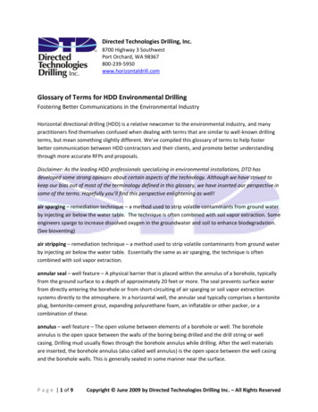
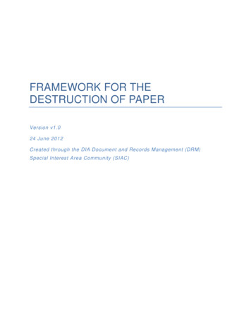
2wellbore observations from EGS projects indicate that flowshave typically been localized at discrete zones along the wellbore and correlate with the locations of preexisting fractures.This may be caused by mechanical instabilities in the rockmatrix during stimulation [13]. Therefore, the destructionand stability of the granite that surrounds boreholes underthermo-hydro-mechanical coupling are essential factors thatrestrict the efficient extraction of HDR geothermal energy.Borehole damage is caused by stress concentration at thecross-section of the wellbore [20]. At room temperature, rockcut from the original location during the drilling processleads to a loss of support in the rock around the borehole.Intragranular and transgranular microcrack expansions aregenerated in the granite around boreholes, which can causethe exfoliation of local minerals and lead to borehole failure[20]. Subjected to continuous loads such as hydraulic pressure and stress, the rock crack rheological fracture can takeplace as time goes, which results in reduced stability of theborehole surrounding rock mass [21]. In high-temperaturedrilling processes, mud circulation is used to cool the bit.During the exploitation of HDR geothermal energy, wateris injected into the reservoir for heat exchange to rapidly coolthe hot rock mass close to the injection wells while theperipheral rock mass undergoes slow cooling. The suddendecrease of temperature around the wellbore, i.e., thermalshock, causes thermal cracking. Normally, the degradationof the rock mechanical properties under thermal shock isgreater than that under slow cooling [22]. Hence, duringthe extraction of HDR geothermal energy, the boreholes areunder the conditions of high temperature and pressure,which increases the complexity of the destruction law of thegranite surrounding the borehole.Zhao [23] simulated the drilling process at different temperatures at a 4000 m depth (100 MPa) in his doctoral thesis.He found that there were no obvious cracks around the borehole at 150 C. When the temperature increased to 300 C, several radial cracks appeared around the borehole and rockparticles on the inner wall of the borehole fell off. At 500 C,the radial crack width around the borehole increased significantly, and a severe fracture zone appeared in the borehole.Zhao et al. [24] performed stability experiments of granitedrilling under high temperature and pressure. They found alarge number of cracks around the drill hole during theexperiments and presented deformation laws of the rockand boreholes as functions of temperature and pressure whilenoting that the critical conditions for drilling instability are500 C and 150 MPa of hydrostatic pressure. Kumari et al.[25] studied the effect of reservoir depth, temperature, andsample heterogeneity during hydraulic fracturing and theinfluences of rock microstructure on fracture propagation.Zhou et al. [26] conducted a hydraulic fracturing experimentunder high temperature and pressure with large samples andfound that the mechanism for decreased crack initiationpressure is the thermal shock generated by the action of fracturing fluid of rock at high temperature. Brudy and Zoback[27] studied the failure of boreholes in two geothermal projects in Kontinentales Tiefbohrprogramm der Bundesrepublik (KTB) in Germany and Soultz in France. The researchindicated that cold mud circulation during the drilling pro-Geofluidscess leads to a cooling contraction of the rock surroundingthe borehole, and the resulting thermal stresses induce tensilecracks. Cornet et al. [28] conducted large-scale water injection experiments in a geothermal reservoir at a 5000 m depthin Soultz. The test results and borehole images showed thatwhen the pore pressure increases by more than 10% of theminimum principal stress, massive shear failure can occurin the injection wells and reservoirs.The above research describes drilling failure during thedevelopment of typical HDR geothermal resources aroundthe world and introduces the results of drilling, hydraulicfracturing, and borehole stability under triaxial stresses(σ1 σ2 σ3 ) in the laboratory. However, horizontal groundstress inequalities (σ2 σ3 ) have a significant influence onborehole failure for the high-temperature rock mass. Owingto limitations in experimental equipment, laboratory studieson borehole failure under high temperatures and true triaxialstresses (σ1 σ2 σ3 ) have been rarely reported.This work used the “true triaxial heat injection rockmechanics experimental system” developed by the TaiyuanUniversity of Technology to perform destruction tests on aborehole under true triaxial stress (σ1 4:5 MPa, σ2 1:0MPa, and σ3 0:5 MPa) when a superheated, 500 C, hightemperature steam is injected. The failure law and drillingmorphology under the effect of solid-flow-heat couplingwere analyzed to further study the failure mechanism of production wells for HDR geothermal energy extraction. Thestudy showed how thermal cracks and fractures initiate andpropagate in borehole surrounding rock under thermohydro-mechanical coupling. The results of this work can beapplied to study hydraulic fracture propagation in geothermal reservoirs, and it is useful to assess the stability of borehole surrounding rock in HDR geothermal resourceextraction.2. Materials and Methods2.1. Experimental Equipment. The true triaxial heat injectionrock mechanics experimental system (shown in Figure 1)consists of a high-temperature steam generation system, truetriaxial pressure equipment, and a testing system. The hightemperature superheated steam is produced from a gasboiler, where the maximum operating temperature and thehighest steam pressure are 600 C and 3 MPa, respectively.The true triaxial pressure equipment has a maximum axialload of 100 tons and a maximum lateral load of 60 tons. Anacoustic emission (AE) measurement system (DISP-PCI2,Physical Acoustics Corporation (PAC)) was used to recordall emissions generated during the destruction tests for thegranite samples. A dial gauge was used to test the deformation of the sample.2.2. Samples. The samples were made with Shandong greygranite from Pingyi, Shandong province, China, and werein a natural water state with a density of 2.71 g/cm3, sized at300 300 300 mm. A hole (diameter φ 20 mm, height h 180 mm) was drilled at the center of each sample, as shownin Figure 2(a). The uniaxial compressive strength of theShandong grey granite was 130.5 MPa, and the single axial
Geofluids3Inlet of steamSteam generation systemTrue tri-axial pressure equipmentTop pressure platensampleOutlet of steamAcoustic emission(b)GrooveSteel tube(a)(c)Figure 1: Experimental equipment: (a) true triaxial heat injection rock mechanics experimental system; (b) sample; (c) top pressure platen.High temperatureresistant adhesiveAsbestos board(a)(b)(c)Figure 2: Granite sample: (a) drilling in the sample center; (b) application of the high-temperature-resistant adhesive to the samples; (c) fixthe asbestos board to the samples with the high-temperature-resistant adhesive.Table 1: The mineralogical compositions of Luhui tassiumfeldspar40-45%35-40%Quartz Biotite2025%2-5%tensile strength was 10.4 MPa. The mineral compositions ofthe material are shown in Table 1.2.3. Experiment Procedures. Zhao et al. [16, 24] reported thatthe critical conditions for drilling instability are 500 C and150 MPa of hydrostatic pressure. Thermal cracking mainlyoccurs at grain boundaries as intergranular microcracksalong with apparent weaknesses that develop with rising temperatures. Intragranular cracks are observed when heating to500 C, indicating that thermal cracking in granite under hightemperature and pressure is induced by both the intragranular and intergranular thermal stresses. Therefore, the superheated steam injected into the sample for the experimentwas at 500 C.The specific loading methods are shown in Figure 3. Sensors that monitor the steam temperature and pressure wereplaced at the inlet. Technology utilizing AE was employedto monitor thermal cracking with four AE sensors placedon the four sides of the samples (Figure 3). Four holes weremachined in the four-side pressure platen to ensure the AEsensors were in direct contact with the rock sample. Environmental noise (generated by the operation of the gas boilerand pressure equipment) was tested before the experiment.The AE-measured amplitude of the noise was between 20and 40 dB. Therefore, the threshold value of the AE was45 dB, the preamplifier gain was set to 40 dB, and the sampling rate was 5 MSPS (mega samples per second, 5 MSPS 5 MHz).Superheated steam at 500 C and 2.8 MPa was injectedinto and flowed through the borehole. To ensure constantsteam pressure, a counterbalance valve was assembled atthe end of the outlet. The superheated steam was first injectedinto the borehole via the inlet and then flowed directly intothe bottom of the borehole via a steel tube to ensure therewas no water in the borehole. The superheated steam flowedout of the borehole via the outlet after heating the surrounding rock, as shown in Figure 3.An asbestos board and a high-temperature-resistantadhesive were used to seal the injection well during the experiments. The asbestos board was fixed on the samples with ahigh-temperature-resistant adhesive (see Figure 2) to ensurethere was no steam leakage between the sample and theasbestos board. Several grooves were machined on top ofthe pressure platen (see Figure 1(c)) to ensure there was no
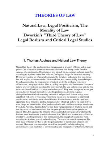
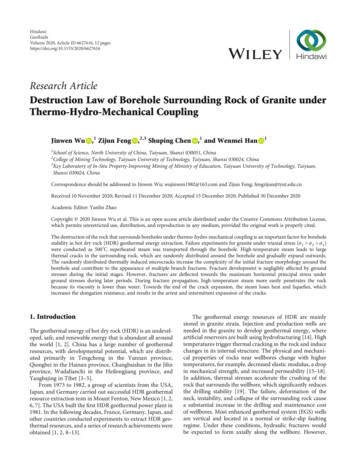
4Geofluidsσ1 4.5 MPaCounter balance valvePressure gaugePressure platenCVPOutlet of steamValveVGas boilerInlet of steamAE sensorAE sensorTThermocoupleSteel tubeAE sensorBore holeσ2 1.0 MPaSampleAE sensorσ3 0.5 MPaFigure 3: Schematic diagram of the experimental setup.Injection steam pressure me (min)Figure 4: Injection steam pressure-time curve.steam leakage between the asbestos board and the pressureplaten under axial pressure.3. Results3.1. Sample Destruction. Figure 4 shows the experimentalpressure-time curve. The experiment lasted 210 min. Thesuperheated steam at 500 C was first introduced into theborehole while the pressure was increased at a slow rate of0.08 MPa/min. The pressure reached its nominal value of2.8 MPa after 36 min. During this process, the sample didnot undergo macroscopic damage. Subsequently, the samplewas macroscopically destroyed after approximately 200 minwith constant steam pressure of 2.8 MPa while the steamleaked from the side of the sample.Figure 5 demonstrates the spatial pattern of the fracturepropagation in the sample. Several fractures appeared duringthe fracture initiation period; these were all vertical fractures.Three of them penetrated the sample, and one changed direction and stopped after extending for a distance. Wing-A wasinitiated along the direction of the minimum horizontal principal stress. During the expansion process, Wing-A graduallydeflected towards the maximum horizontal principal stress.The fractures then propagated to the side and bottom ofthe sample (Figure 5). Wing-B was initiated at 30 degreesfrom the maximum horizontal principal stress and graduallyturned towards the maximum horizontal principal stressbefore going through the sample. Wing-C was initiated andextended along the maximum horizontal main stress directionand also went through the sample. Wing-B and Wing-C onlypenetrated the side of the sample, and there was no fracture atthe bottom. The expansion of the Wing-A, Wing-B, andWing-C fractures along the height direction (300 mm) wasmuch larger than the depth of the hole (180 mm). Wing-Dstopped expanding relatively quickly after fracture initiation.Wing-C is a typical tensile crack, while the appearances ofWing-A, Wing-B, and Wing-D are the results of the jointaction of shear and tension.There were several bifurcations in the fractures aroundthe wellbore, especially for Fracture A (see Figure 5), whichextends along the direction of the minimum horizontal principal stress. Figure 6 shows magnified views of the bifurcations, which are located on the side of the sample, as seenin Figure 5. Tomac and Gutierrez [29] have shown that whenthe brittle rock is in the solid-fluid-thermal coupled field andconvective heat transfer is considered, secondary cracksoccur along the main fracture, and the low-viscosity fracturing fluid is more likely to cause additional finger-like cracksto appear near the main fracture. High-temperature superheated steam has lower viscosity than water, and convectiveheat transfer occurs during the experiments. The hightemperature steam is a fracturing medium and the main reason for the frequent crack bifurcations. In the fracture initiation stage (Stage I of Fractures A, B, and D, as seen inFigure 5), the extension direction of the fractures is affectedless by the horizontal principal stress. In the later stage ofthe expansion (Stage II of Fractures A and B, as seen inFigure 5), the fractures are deflected towards the maximumhorizontal principal stress due to the influence of the horizontal principal stress. The thermal stress caused by hightemperatures is the main reason for the complicated fracture
Stage IIStage IStage IIStage I𝜎H 1.0 Mpa𝜎h 0.5 MpaFigure 5: Spatial pattern of the fracture propagation.Time (min)0.2Bifurcation-1Bifurcation-2Figure 6: Bifurcations in the cracks.Deformation (mm)0.00306090120150180210240 0.2 0.4 0.6 0.8 1.0geometry, which manifests in the form of multiple fractures.The cracks in a rock mass typically reduce the overallmechanical behaviors of the rock mass [30, 31].3.2. Deformation. Figure 7 indicates the deformation of thesample; the superheated steam pressure in the hole increasesfrom 0 to 2.8 MPa (0 to 33 min). The axial deformation iscompression deformation, and the lateral deformation isexpansion deformation. The axial compression deformationrate decreases with the increase of pressure, and the lateralexpansion deformation rate increases with pressure. Afterconstant steam pressure of 2.8 MPa from 33 to 108 minutes,the lateral deformation continues to climb, and the deformation is basically linear with time. The axial deformation gradually transforms from the form of compression to that ofAxialMin horizontal stress directionMax horizontal stress directionFigure 7: Deformation of the sample.expansion. At about 108-110 min, the 0.3 mm expansionoccurs in the direction of the lateral maximum horizontalprincipal stress in 2 minutes, and 0.6 mm expansion appearsin the lateral minimum horizontal principal stress in thesame period. From 110 to 200 minutes, the specimen keepsexpanding, the lateral deformation rate becomes stable, andthe axial deformation rate gradually decreases until the specimen is destroyed.
10024012140010120010008800660044002AE energy (mVms)GeofluidsAccumulated AE energy (104 mV ms)62000003060Time (min)90 120 150Time (min)180210240Accumulated AE events /102 timesAccumulated AE counts /103 timesAE counts /times(a)(b)Figure 8: Variation in the AE energy with time.3.3. Acoustic Emission Feature. When the mineral particles inthe rock are shifted or microcracking occurs, the strainenergy is released in the form of elastic waves, which causeAE events. During the loading process, each AE event corresponds to the occurrence of a microfracture within the rock;hence, there is a corresponding relationship between the AEevent and the fracture expansion [32, 33].The AE energy reflects the energy level of the stress wavesproduced by crack propagation, which characterizes thecrack propagation activity within the rock samples. The accumulated energy of the AE events reflects the energy necessaryto cause crack initiation and extension. The AE event andcount reflect the frequency of microcracking.Figure 8 shows variations in the AE event, count, andenergy that were collected during the experiment. The AEcount and energy were low from 0 to 100 min, and an intervalbetween the quiet zone and the concentrated area appeared atthis time. Thus, the accumulated count and energy of the AEincreased slowly. The AE count and energy were high from100 to 110 min, and the accumulated event, count, andenergy of the AE increased rapidly. From 110 to 160 min,the AE count and energy slightly reduced but were still higherthan at the initial stage of the experiment, which caused theaccumulated event, count, and energy to increase more slowly.After 160 min, a second AE concentration area appeared, andthe cumulative parameters increased rapidly until the samplewas destroyed.From 100 to 110 min, the AE event, count, and energyincreased rapidly. At this point, the sample did not experience macroscopic damage, and there was a substantialincrease in the intensity and the frequency of AE signals. Thisindicates that the fracture initiation occurred around theborehole of the sample.4. Discussion4.1. Macrocrack Initiation. In Figure 8, from 100 to 110minutes, the occurrence of AE count and energy increased,the accumulated event, count, and energy of the AE increasedrapidly. These AE activities are believed to be an indication ofhydraulic fracture initiation [30]. From Figure 7, it can beseen that at 108-110 min, 0.3 mm expansion deformationoccurs in the direction of the lateral maximum principalstress of the rock, and 0.6 mm expansion deformation takesplace in the direction of the lateral minimum horizontal principal stress. The results of deformation and AE in the experiment indicate that large-scale destruction occurred withinthe sample during 100-110 min. The initiation of crack happens, and macrocrack initiation develops.AE localization events are microcrack damages monitored in real time. They can reflect the accumulation ofmicrofaults and the evolution of macrocrack formation.Deformation can only reflect the results of the macrocrackdevelopment of the specimen but cannot reflect the processof accumulation of microfaults. The judgment of the momentof the macrocrack initiation by the deformation is delayedcompared with one of the acoustic emission characteristicparameters. Hence, AE technology is an effective method topredict fracture initiation.4.2. Destruction Rules of the Borehole. The AE event locationsrecorded during the experiments were used to estimate thefracture propagation in the rock surrounding the borehole.The fundamental basis for calculating the location is the simple time-distance relationship as implied from the velocity ofthe sound wave.Figure 9 shows the AE location map for the destruction,which reflects the fracture law of the sample at differentexperimental stages. The acoustic locations obtained at thedifferent stages are indicated by different colors. Figure 9(a)shows the surface morphology of the sample after failure,Figures 9(c)–9(f) indicate the thermal crack locations aroundthe borehole before fracture initiation, and Figures 9(b) and9(g)–9(n) demonstrate the location of the AE during theperiod from fracture initiation to macroscopic failure. Themaximum experimental steam pressure was 2.8 MPa, which
Geofluids73002001000050100𝜎H 1.0 MPaC150DA200𝜎h 0.5 01502002002502500-18 min0-33 1502002002500-67 min2500-100 0200200250100-110 min00300250100-117 min(g)300(h)Figure 9: Continued.
00200250100-133 min250100-150 150200200250100-167 min250100-183 0200200250100-200 min00300(m)250100-210 min300(n)Figure 9: AE location map at different stages: (a) macroscopic failure of the sample; (b) AE location after failure; (c) AE location at 0-18 minin the thermal cracking stage; (d) AE location at 0-33 min in the thermal cracking stage; (e) AE location at 0-67 min in the thermal crackingstage; (f) AE location at 0-100 min in the thermal cracking stage; (g) AE location at 100-110 min in the fracture initiation stage; (h) AElocation at 100-117 min in the fracture propagation stage; (i) AE location at 100-133 min in the fracture propagation stage; (j) AE locationat 100-150 min in the fracture propagation stage; (k) AE location at 100-167 min in the fracture propagation stage; (l) AE location at 100183 min in the fracture propagation stage; (m) AE location at 100-200 min in the fracture propagation stage; (n) AE location at 100210 min in the fracture propagation stage.is far below the tensile strength (10.4 MPa) of granite. Thesample was destroyed after 200 min under constant pressure(2.8 MPa) during the experiment.The destruction of rock that surrounds boreholes can bedivided into three stages.4.2.1. Thermal Cracking Stage. The high-temperature superheated steam flow causes thermal stresses in the surroundingrock of a borehole, which induces thermal cracking, but isinsufficient to form macroscopic fractures. At this stage,the main factor impacting the thermal cracking of the sample is the thermal stress caused by the high-temperaturesuperheated steam flowing in the borehole, while the triaxialstress is the secondary factor. Figures 9(c) and 9(d) show thethermal crack AE location events as the steam pressureincreased from 0 to 2.8 MPa (0-33 min) in the borehole,and Figures 9(e) and 9(f) show the AE events during theconstant pressure process (33-100 min). The thermal crackswere randomly distributed around the borehole and gradually expanded outwards with the borehole at the center. During this process, the density of the thermal cracks around theborehole gradually increased.As can be seen from Figure 8, the AE energy of the thermal cracking is lower than those during fracture propagation,while the quiet section and the dense section of the AE eventsappeared alternatively. Thermal cracking is the result of thealternating accumulation and release of energy as generatedby the deformation mismatch between grains with differentthermal expansivities. The thermal cracking of granite occursmainly at grain boundaries, while cracks in the grains occur
Geofluidswhen the granite is heated to 500 C [15, 16]. A large numberof thermal cracks occurred around the borehole, and theaccumulation of these microcracks promotes the formationof the initial fracture.4.2.2. Fracture Initiation Stage. Figure 9(g) indicates the location of the AE during the fracture initiation stage (100110 min). After the thermal cracking stage, the density ofthermal cracks around the borehole increased, and microcracks connected to each other and expanded to form the initial fracture. As seen in Figure 8, the energy of the AE waslarge at this stage, and the cumulative parameters increasedrapidly. The location of the fracture initiation was randomand nearly independent of the ground stress. There were fourinitial fractures randomly distributed around the borehole, asseen in Figure 6. Theoretically, initial fractures should be initiated along the maximum horizontal principal stress (e.g.,Fracture C in Figure 5), but Fractures A, B, and D (inFigure 5) violated the above law.Under thermo-hydro-mechanical coupling, propagationof macrocracks was affected by the combined effects of thehorizontal principal stress, the existing thermal cracks, andthe shape of mineral grains. At a temperature above 300 C,a macrocrack was formed by connecting the thermal cracksduring its propagation [34]. Moreover, thermal fracturesallow the steam at high pressure to penetrate into and causestress concentration around the fracture tips, potentiallypushing the thermal fractures to propagate further [35].There were large thermal cracks around the borehole, asshown in Figure 9. Hence, the randomness of the spatial distribution for thermal cracking is favorable to the formation ofmultiple weak sections around the borehole. This easilyforms multiple initial fractures that are barely affected bythe horizontal principal stress.4.2.3. Fracture Propagation Stage. Figures 9(g)–9(n) show thetime-order characteristics of the AE localization events during fracture propagation (110-210 min) in the sample. TheAE events were densely distributed around the boreholeand along the fracture direction. Fracture A, which is in thedirection of the minimum horizontal principal stress, wasformed earlier (Figure 9(g)), and Fractures B and C, whichare in the direction of the maximum horizontal principalstress, appeared soon after (Figures 9(h)–9(j)). Due to thesmall size of Fracture D, the AE location is unknown. Inthe initial fracture propagation stage, the extension directionof the fractures was affected less by the horizontal principalstress. In the later stage of fracture expansion, the fracturesdeflected towards the maximum horizontal principal stressdue to the influence of the horizontal principal stress.The time-order characteristics of the AE localizationevents in Figures 9(h)–9(j) indicate that Fracture A underwent a process of expansion, crack arrest, and reexpansion.When Fracture A was experiencing crack arrest, initial fractures were formed for Fractures B and C, and three cracksexpanded together thereafter (133-223 min). Crack expansion always occurs along the easiest direction. The intermittent expansion of Fracture A indicates that the energy forcracking is insufficient, and the maximum horizontal princi-9pal stress cannot be overcome. Therefore, the energy needs tobe accumulated.The thermal cracking is favorable to form multiple initialfractures around the borehole, which are barely affected bythe horizontal principal stress (seen in Figure 6). The hightemperature effect (thermal stress) is the main reason fo
superheated steam flowing in the borehole, while the triaxial stress is the secondary factor. Figures 9(c) and 9(d) show the thermal crack AE location events as the steam pressure increased from 0 to 2.8MPa (0-33min) in the borehole, and Figures 9(e) and 9(f) show the AE events during the constant pressure process (33-100min). The thermal cracks