Transcription
Lecture 3 - FootingsFootings Factors influencing footing type Design considerations Reinforced concrete properties Footing typesDesign for structureActions – concentrated or distributed forces (direct actions) acting on a structure or deformation orforces constrained within it (indirect actions) Building life (N) (assumed to be 50 years) Permanent actions – dead load (G) Earthquake actions Earth pressure (Fe) Ground water action (Fgw) Liquid pressure action (Fip) Ice and snow actions (Fice & Fsn) Imposed snow action (live load) Wind action (W)Factors affecting choice of footing system (& structure)Building typology Design (Seijmas point loads VS Diestas unformly distributed load) Use (e.g factory loading vs house) Materials (Seijmas lightweight vs Diestas mass) Building systems (Seijmas steel column system vs Diestas masonry)Factors affecting choice of footing system Foundation properties Impact on adjacent properly or retaining wall conditions Below ground infrastructure and site features Soil stability Climatic effects Constructability Construction time and program Occupational health and safetySummary Foundation conditions are the most important factor in design of footings BUT Design typologyo Briefo Useo Cost Construction efficiencyo Timeo Safety
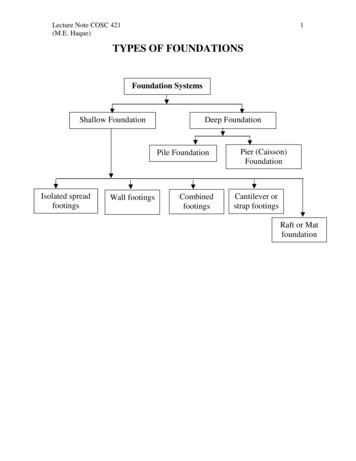
Footing typesShallow footings Transference of load relatively close to main building or sub-structure due to foundation ofadequate bearing capacity (raft pads tend to be shallow)Deep footings Footing transfers load through soil of inadequate bearing pressure to deeper layers of soilhaving adequate bearing pressure or acts through friction between footing and surrounding soilBlinding Concrete Blinding – layer of concrete between 50-100mm thick, put down on soil to seal the ground andprovide a clean and even surface for construction work. Also assists to clean the base of theexcavation if required as the base of excavation is sealed by the concrete Primarily used just to level the ground off
Mass concrete Unreinforced concrete, of a known compressive strength Used whereo Soil conditions are poor – usually due to depth of a bearingo Bearing is at a depth where standard footing design is not achievable or uneconomicalor where safety is an issueo To avoid load transference at a particular level, due to site conditions (trees, adjacentstructures) Acts as a quasi-foundation/footing system in compression – no reinforcement used Replacement of poor soil with “good soil” (concrete of a known compressive strength)o Excavation is carried out and trench filled with lesser strength concreteo Standard footing design then poured over this mass concrete base Cheap and quick to do so builders like it
Underpinning New support structure underneath the existing footing without the removal of thesuperstructure Transfers load to a new bearing level at a lower depth Prevents collapse due to excessive or uneven settlement Allows additional loading of building Enables ground level inside or outside to be loweredHow to do underpinning Continuous strip footings – simplest method Removal of sections of soil at consistent intervals below footings Filing on of these sections with new footing system Sections allowed to set Remaining soil intervals removed and these provided with new footing
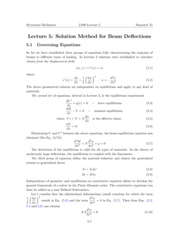
Spread footingsTypes of shallow (spread footings Stripo Takes a continuously distributed loado Continuous footingso Stepped footing Pado Takes a point or concentrated loado Isolated footing Rafto Can take either or both loads – concentrated or distributedo Thickened slab footingStrip footings Supports a continuously distributed load In reactive soils they may act as beams, hence, need to be mindful of bending behaviour Generally rectangular in shape, with greater depth than width due to support requirement ofwall above it Longitudinal bars control concrete shrinkage and cracking Reinforcement at bottom of footing is tensile resistance bending form above Reinforcement at top of fitting is tensile resistance bending from belowSite slope Sloping site topography may require footing to be stepped Structural continuity and integrity to be maintained Concrete and reinforcing overlappedPad footings Supports a point load – square or rectangular in plan, supporting a single column Area is a factor of the load and the bearing capacity Depth is a factor of shear (column cant punch through) and bending (dishing of side, tensilestress at the bottom) Reinforcement critical at base not at top, reaction of the ground acts upwards on all sides of thecolumns – counteracts the upward pressure exerted by the soil and downward pressureexerted by the column Greatest bending and shear is under the column
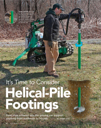
Raft footings Extends completely under the building footprint so as to spread weight over the entirefoundation area Used when loads become so large that it is more economical to join up all the pad footings thatwould be requiredo Column grid say 8m x 8m – pads 3m x 3m (for 4 flootr) increase load (more floor levels)pads must be bigger (may end up touching) so easier to join up into a raft Used where ground conditions poor, raft required to distribute the loads over a larger area Very stiff footing good in dealing with settlement and differential movemento Better than individual footings which are more suspectible to local differentialsettlement Depth of rafto To deal with shear of columnso A factor of the large load from floors aboveo Often at least 1-1.5 metres deep Raft wants to bend between columns, so need to make it very stiff but using lots ofreinforcementPile footings End bearing – taken through soil of poor bearing capacity to a level of good bearing capacity Friction piles – soil generally all poor so length of pile is determined by resistance generated byfriction Bored piles – can be a combination of the above. In effect drilled holes, sometimes wide atbottom. Generally insitu reinforced concrete. Canst use them where soil is prone to collapse,like silt soils Driven piles – like nails, driven to refusal (can be concrete or steel, precast/prefabricated).Docklands driven to 25-30m – Coode island silt Designed as long columnds – reinforcement for driven piles robust enough for impact load,bored piles reinforcement deals with slenderness of column and buckling even thoughrestrained by soil Generally have a pile capping beam to connect piles and distribute load across piles Uplift / shear can be generated by driven piles – the reinforcement design is importantPile Footing Systems Driven Pileso A pile of steel, timber or precast concrete which is forced into the soil by blows from apile hammer Bored pileso A pile, with or without steel casing, formed by excavating or boring a hole in the groundand sub sequentially filling it with plain or reinforced concrete
Reinforced concrete slabs There are a number of types Most common stiffened rafto Slab and beams poured at same timeo Integrated systemo Slab panel (relatively think 100mm ) is stiffened by introduction of edge beams andinternal beamso Spacing of beams as a factor of spanning capacity of panel, loading condition andfoundationo Beams need to be supported by foundation of adequate bearingo Panels need to be supported by ground or compacted fillSummary Different footing systems respond to different design conditions Primary systemso Mass concrete (blinding not a footing)o Underpinning (lowering load transfer or increasing capacity)o Strip footingso Pad footingso Pile footings Reinforcement design is criticalo Typeo Configurationo ProtectionConcrete compositionAirPortland cement6%Workability11%BinderCoarse aggregateFine aggregate(gravel or crushed (sand)stone)41%26%Density, strength thermal conductivity, heatstorage capacity, workabilitySpecifying and ordering concreteConcrete classes Normal class Special classOrdering Strength - 30 MPa Aggregate size - 20mm Slump - 80mmTesting Slump test Compaction test (7, 14, 28 days)Water16%Setting agent forbinder
Reinforced ConcreteConcrete: High compressive strength but low tensile strength Low strength to weight ratio Tensile stresses develop under load, shrinkage or temperature change As low tensile strength it will fail suddenly and completely when first cracks forms – susceptibleto crackingSteel Steel – very high tensile strength and high compressive strength, but expensiveHigh strength to weigh ratioCan take increased load when it enters an elastic stage and then fails when ultimate stressreached. Deformation occurs prior to failureReinforced concrete Combines high tensile strength of steel and relatively low-cost compressive strength ofconcreteReinforcementYield stress Max useable strength Point at which steel behaves plastically and is permanent deformed (reo steel 500 MPa)Ductility Ability to undergo deformation and deflection when loaded Avoidance of brittle failure (L- low, N-normal, E-Seismic)Reinforcement placement is critical – must be in correct plane for tensile resistance and must beprojected by concrete coverMesh – Square and Rectangular (Slabs and Pads)
Trench Mesh (Strip Footings) Ribbed bars 500 MPA Main wires and cross wires at 300mm centres Strip footings and slab beamsReinforcing Bars
Week 3 – Footings - Case Study ProjectBored piers Bored piers to be founded into highly to moderately weathered basalt at depths of minimum4.6 metres below existing groundUnderpinning Underpinning adjacent structure Depth of underpinning determined by lowest depth of new footing system Existing footing spans across underpinsSoldier Piles Retaining (shoring) system to hold back soil to allow excavation on one side of the shoringmembers Can also be used as a support mechanism to transfer load from existing structuresCapping beams Beams poured on top of piles Important structural component as they distribute load across a number of piles (in this sensethey act like a footing) Can be designed to tie piles together and prevent lateral displacement (pile beams) Blinding concrete under the capping beam provides an even and level base
Footing beams Element is built directly onto this footing Not incorporated as part of the floor slab Precast wall bears directly onto footing (beam)Ground beams Integral to functioning of the slab Acts to stiffen the slab Slab panels span from integrated beam to integrated beam Slab and beam are poured together Critical as entire slab acts as if it is suspended – not relianton ground for support Beams are supported by pilesSummary Different types of footings are suitable for different design conditions Primary issues are related to load and soil type Form that footing takes related to how loads are dealt with and how they are transferred intothe foundation material
o Mass concrete (blinding not a footing) o Underpinning (lowering load transfer or increasing capacity) o Strip footings o Pad footings o Pile footings Reinforcement design is critical o Type o Configuration o Protection Concrete composition Air Portland cement Coarse aggregate (gravel or crushed stone) Fine aggregate (sand) Water 6% 11% 41% 26% 16% Workability Binder Density, strength thermal .