Transcription
IECM Technical Documentation:Amine-based Post-CombustionCO2 CaptureCompiled in January 2019
IECM Technical Documentation:Amine-based Post-CombustionCO2 CapturePrepared by:The Integrated Environmental Control Model TeamDepartment of Engineering and Public PolicyCarnegie Mellon UniversityPittsburgh, PA 15213www.iecm-online.comForU.S. Department of EnergyNational Energy Technology LaboratoryP.O. Box 880Compiled in June 2018
Table of 3.6.5.6.28Capital Cost . 28O&M Cost . 33Incremental Cost of Electricity . 35Cost of CO2 Avoided . 35Parameter and Model Updates for Advanced Amine-based CO2Capture System5.15.214Process Simulation Tool . 15Methodology . 153.2.1. ProTreat Simulation Runs for CO2 capture and separation from flue gas . 153.2.2. ASPEN-Plus Simulation Runs for CO2 Compression . 163.2.3. Regressions using SAS to derive performance equations . 16Performance Parameters . 163.3.1. Parameters obtained from the “reference base plant” . 173.3.2. Parameters to configure the CO2 system . 173.3.3. Parameters controlling the performance of the CO2 system . 17Performance Equations . 23Model Outputs . 24Characterization of Uncertainties . 27Cost Model Development4.14.24.34.49Historical Developments . 9Process Description . 11Process Chemistry . 12Process Equipment . 12Limitations of the MEA Process . 14Performance Model Development3.1.3.2.4.Technology Options for CO2 Capture . 5Post-combustion amine-based absorption of CO2 from flue gases . 6Model Configuration Options . 7Amine-based CO2 Capture Systems2.1.2.2.2.3.2.4.2.5.536PC Base Plant Updates . 36Parameter and Model Updates for Advanced Amine-based CO2 Capture System . 385.2.1 Parameter Updates for Advanced Amine-based CO2 Capture System. 385.2.2 Model Adjustments for Advanced Amine-based CO2 Capture System . 415.2.3 Menu Updates to the IECM CO2 Capture System . 435.2.4 Case Studies of PC Plants . 455.2.5 Cost Sensitivity . 54ReferencesIntegrated Environmental Control Model - Technical Documentation57 1
List of FiguresFigure 1. Technology Options for CO2 Separation and Capture .5Figure 2. Technology Options for Fossil-Fuel based Power Generation .5Figure 3. CO2 Capture Plant Configuration Options .8Figure 4. Major Industrial Applications of CO2 Capture Systems . 10Figure 5. Flow Sheet for CO2 Capture from Flue Gases using Amine-based System . 11Figure 6. Cost of Electricity (COE) as A Function of Carbon Tax . 36Figure 7. Updated CO2 Capture, Config Menu . 44Figure 8. Updated CO2 Capture, Capture Menu . 44Figure 9. Capital Costs by Steam Cycle Type vs. Net Power Output . 55Figure 10. Revenue Required by Steam Cycle Type vs. Net Power Output . 55Figure 11. Capital Costs by Coal Type vs. Net Power Output . 56Figure 12. Revenue Required by Coal Type vs. Net Power Output . 56Figure 13. Capital Cost vs. Net Power Output with and without CCS . 57Figure 14. Revenue Required vs. Net Power Output with and without CCS . 57Integrated Environmental Control Model - Technical Documentation 2
List of TablesTable 1. Comparison of Technology Options for CO2 Separation and Capture .6Table 2. Protreat Parameter Ranges (total number of simulation runs: 1983) . 15Table 3. Removal Efficiency of Acid Gases Due to MEA Solvent (90% CO 2 removal) . 19Table 4. Amine System Performance Model Parameters and Uncertainties . 27Table 5. MEA Capital Cost Model Parameters and Nominal Values . 32Table 6. MEA O&M Cost Model Parameters and Nominal Values . 33Table 7: Updated Base Plant Parameters . 37Table 8: Updated Cost Correction Factors by Technology . 37Table 9: Set Parameters CO2 Capture CO2 Capture System Process Config Menu . 38Table 10: Set Parameters CO2 Capture CO2 Capture System Process Performance Menu . 39Table 11: Set Parameters CO2 Capture CO2 Capture System Process Capture Menu . 39Table 12: Set Parameters CO2 Capture CO2 Capture System Process CO2 Storage Menu . 39Table 13: Set Parameters CO2 Capture CO2 Capture System Process Retrofit Cost Menu . 40Table 14: Set Parameters CO2 Capture CO2 Capture System Process Capital Cost Menu . 40Table 15: Set Parameters CO2 Capture CO2 Capture System Process O&M Cost Menu . 40Table 16: IECM Parameters Changed for Case 1 - Supercritical Plants without CO2 Capture . 45Table 17: IECM Parameters Changed for Case 2 - Supercritical Plants with CO2 Capture . 47Table 18: IECM Parameters Changed for Case 3 - Supercritical Plants without CO2 Capture . 49Table 19: IECM Parameters Changed for Case 4 - Supercritical Plants with CO2 Capture . 51Table 20: Summary of Case Study Results. 54Integrated Environmental Control Model - Technical Documentation 3
AcknowledgementsThis documentation is a compilation of three previously-issued reports: Anand B. Rao and Edward S. Rubin. A Technical, Economic and Environmental Assessment ofAmine-based CO2 Capture Technology for Power Plant Greenhouse Gas Control. Prepared byCarnegie Mellon University for the National Energy Technology Laboratory. Pittsburgh, PA 15213,October 2002. Anand B. Rao. Details of a Technical, Economic and Environmental Assessment of Amine-basedCO2 Capture Technology for Power Plant Greenhouse Gas Control. Prepared by Carnegie MellonUniversity for the National Energy Technology Laboratory. Pittsburgh, PA 15213, October 2002. Michael B. Berkenpas, Karen Kietzke, Hari Mantripragada, Sean McCoy, Edward S. Rubin, Peter L.Versteeg, and Haibo Zhai. IECM Technical Documentation Updates, Vol. IV. Prepared by CarnegieMellon University for the National Energy Technology Laboratory. Pittsburgh, PA 15213, November2009.These prior reports were sponsored by the U.S. Department of Energy’s National Energy TechnologyLaboratory under Contract Nos. DE-FC26-00NT40935 and DE-AC26 -04NT4187, and by a cooperativeagreement between Carnegie Mellon University and the National Science Foundation (SBR-9521914).Any opinions, findings, and conclusions or recommendations expressed in this material are those of theauthors alone and do not reflect the views of any government agency.Integrated Environmental Control Model - Technical Documentation 4
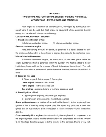
1. Introduction1.1. Technology Options for CO2 CaptureA wide range of technologies currently exist for separation and capture of CO2 from gas streams,although they have not been designed for power plant scale operations (Desideri and Corbelli, 1998).They are based on different physical and chemical processes including absorption, adsorption, membranesand cryogenics. Figure 1 and Table 1 briefly summarizes the salient features of these technology options(Riemer, et al., 1993; Hendriks, 1994; Mimura et al., 1999; Jeremy, 2000; Audus, 2000). The choice of asuitable technology (which mainly depends on the power plant technology) depends upon thecharacteristics of the gas stream from which CO2 needs to be separated. Future power plants may bedesigned so as to separate out CO2 from coal before combustion (using coal-gasification systems), or theymay employ pure oxygen combustion instead of air so as to obtain a concentrated CO2 stream fortreatment. Figure 2 shows the variety of power plant fuels and technologies that affect the choice of CO2capture systems. In this report, post-combustion capture of CO2 from flue gas streams of conventionalpower plant using amine-based absorption systems has been considered.CO2 Separation and er alSystemsGas SeparationAluminaZeoliteActivated CPolyphenyleneoxidePolydimethylsiloxaneGas AbsorptionRegeneration MethodPolypropeleneSelexolRectisolOtherPressure SwingTemperature SwingWashingCeramic BasedSystemsFigure 1. Technology Options for CO2 Separation and CapturePower Generation asedGasOxidantTechnologyAirSimple CyclePure OxygenPulverized CoalGas TurbinesCombined CycleDirect CombustionGas ReformingGTCCIGCCOtherFigure 2. Technology Options for Fossil-Fuel based Power GenerationIntegrated Environmental Control Model - Technical Documentation 5
Table 1. Comparison of Technology Options for CO2 Separation and n(Chemical)Absorber andstripper sectionsChemical solvent(e.g. MEA, HPC)AdvantagesSuitable for dilute CO2streams (typical flue gasfrom power plants)Operates at ordinary T & PCommercially available,proven technologyAbsorption(Physical)Absorber andstripper sectionsPhysical solvent(e.g. Selexol)AdsorptionAdsorber bed(s)Less energy requiredSolvents are lesssusceptible to theimpurities in the gasstreamVery high CO2 removal ispossibleProblems/ DrawbacksThe heat of solventregeneration is very highSignificant solvent lossesdue to acidic impurities inthe gas streamRequires high operatingpressureWorks better with gasstreams having high CO2contentRequires very highoperating pressuresCostlyMembranesMembrane filter(s)Upcoming, promisingtechnologyRequires very highoperating pressuresSpace efficientMay require multipleunits and recycling due tolower product purityVery costly1.2. Post-combustion amine-based absorption of CO2 from flue gasesToday the 300 GW of coal-fired power generation capacity in the U.S. provides 51% of all powergeneration and accounts for 79% of carbon emissions coming from electric utilities. Even with theexpected growth in natural gas for new generating capacity, coal’s share of the electricity supply is stillprojected to be about 44% in 2020, and higher in the absolute amount compared to today, according to thelatest DOE projections [20]. Natural gas use is projected to account for 31% of power generation in 2020.Thus, any serious policies to reduce CO2 emissions during the next two decades must consider not onlythe technology options for new power plants (which is the case commonly discussed in the literature), butalso the retrofitting of existing coal and natural gas plants which will continue to operate for severaldecades to come. This medium-term intervention to reduce CO2-emissions has received very littleattention to date.In current systems which use air for combustion, post-combustion CO2 separation from the flue gasstream has to be carried out. Past studies have shown that amine-based CO2 absorption systems are themost suitable for combustion-based power plants for the following reasons These systems are effective for dilute CO2 streams, such as coal combustion flue gas whichtypically contains about 10%-12 % CO2 by volume.Integrated Environmental Control Model - Technical Documentation 6
Amine-based CO2 capture systems are a proven technology that are commercially availabletoday. Amine-based systems are similar to other end-of-the-pipe environmental control units used atpower plants. These units are operated at ordinary temperature and pressure. A major effort is being made worldwide to improve this process in the light of its potential role inCO2 abatement. Thus, one can anticipate future benefits from technology advances.1.3. Model Configuration OptionsFor post-combustion CO2 capture from flue gas, the amine-based CO2 capture system, which is thecurrent commercially available technology, has been chosen for this model. There is a major R&D effortgoing on worldwide to improve this technology – mainly to reduce the high energy penalty of thistechnology. A substantial part of the energy requirement consists of heat or steam requirement forsorbent regeneration. Depending upon how this steam is supplied, there are three configuration optionsavailable. These are shown graphically in Figure 3 and described below.Base plant de-rating: Here, the low-pressure (LP) steam is extracted from the steam cycle of the powerplant and supplied to the reboiler for sorbent regeneration. Extraction of steam leads to loss of powergeneration capacity, and the net plant output decreases substantially. In case of a new plant to bedesigned with CO2 capture system, it is possible to optimally design the steam cycle to take care of thesteam requirement of the amine system, and proper heat integration may help in reducing the energypenalty. In case of an existing coal plant to be retrofitted with amine system, optimal heat integrationmay not be achievable, and is likely to lead to much higher energy penalty due to steam extraction.Auxiliary Natural Gas Boiler (w/ Steam Turbine): Another potential option to provide the energy forthe amine system is by adding an auxiliary NG-fired boiler. Often it would be combined with a steamturbine which could generate some additional power (mainly used to supply electrical energy demand ofCO2 capture unit), and the LP steam would be then used for sorbent regeneration. Thus, the originalsteam cycle of the power plant remains unperturbed and the net power generation capacity of the powerplant does not get adversely affected. Again, it comes at an additional cost of capital requirement for theboiler (and turbine) and the cost of supplemental NG fuel. Also, the combustion of NG leads toadditional CO2 emissions (and NOx emissions). So, there are at least two possible sub-options available1. The flue gas from the auxiliary boiler is cooled down to acceptable exhaust temperature and thendirectly vented to the atmosphere. Here, the net CO2 capture efficiency of the system issubstantially lowered because of the additional CO2 emissions from NG boiler. Also, the totalNOx emissions may exceed the allowable levels of emission. So, the flue gas from the auxiliaryNG boiler may have to be treated for NOx removal before venting.2. The CO2 capture system maybe designed so as to capture CO2 from the additional flue gas aswell. In this case, the secondary flue gas stream (after cooling and NOx removal, if required)maybe merged with main flue gas stream, before it enters the CO2 capture system. If the NG fuelcontains H2S, the secondary flue gas may have to be treated for SOx removal as well. The basicpurpose of the auxiliary NG boiler is to provide the steam required for sorbent regeneration.With higher amount of flue gas to be treated (and more CO2 to be captured), the amine-systemwould require more steam and thus a bigger auxiliary NG boiler would be required (which meansmore secondary flue gas!). An optimal size of auxiliary NG boiler maybe determined by aniterative calculation procedure, so that it matches the sorbent regeneration steam requirement ofthe CO2 capture system treating the total flue gas. Thus, the CO2 capture level is maintained tothe originally desired level, but it often requires substantially big auxiliary NG boiler facility.This may not be always practically feasible (space constraints for retrofit applications, fuelIntegrated Environmental Control Model - Technical Documentation 7
availability, etc.) and economically viable (higher capital cost of building a bigger CO2 capturesystem as well as an auxiliary boiler, higher O&M costs etc.). In the present version of IECM,this configuration option is not included.Figure 3. CO2 Capture Plant Configuration Optionsa)Reference base plantb)Capture plant with internal deratingc)Capture plant with an auxiliary boiler and a secondary steam turbineIn terms of the configuration of the CO2 capture system shown in Figure 3, the user can make thefollowing choices as wellDirect contact cooler: The default setting in IECM chooses to include a DCC to cool the flue gas beforeit enters the amine system. The temperature of the flue gas affects the absorption reaction (absorption ofCO2 in MEA sorbent is an exothermic process favored by lower temperatures). Also, the volumetric flowrate of the flue gas stream, which is a key determinant of the sizes of various equipments (direct contactcooler, flue gas blower, absorber), is directly related to the flue gas temperature. Hence lower flue gastemperature is desired. The typically acceptable range of flue gas temperature is about 50-60 oC. If theflue gas is coming from wet sulfur scrubber, additional DCC may not be required. But in case of flue gasfrom NG-fired boiler, which often does not pass through a sulfur scrubber, DCC is a must.Choice of sorbent: At this time, MEA is the default sorbent used in the system and the nominal values ofvarious parameters are based on a process simulation model that uses MEA. As always, the users canIntegrated Environmental Control Model - Technical Documentation 8
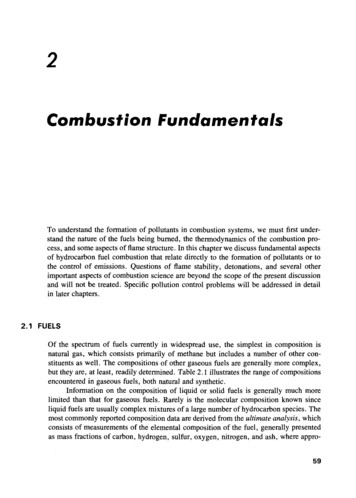
overwrite the nominal values of these parameters if they wish to use a different sorbent (and have therelevant data). In future, the model can adopt a different sorbent by providing the appropriate values forthe key parameters.CO2 transportation: The default mode of CO2 transportation is via pipelines. The user can specify thedistance over which CO2 needs to be carried to, and the unit cost of CO2 transportation. This modulemaybe expanded in future to include detailed parameters about pipeline transport and also other transportoptions.CO2 storage/ disposal: The default option for CO2 disposal is underground geological storage. Anominal cost of 5/ tonne CO2 has been suggested, which can be changed the user to match the specificdetails about the location. If CO2 is being used as a byproduct for EOR or ECBM activity, it maygenerate some revenue. This module, which is represented by a single cost parameter, maybe expandedin future to include details about the various storage/ disposal options.2. Amine-based CO2 Capture Systems2.1. Historical DevelopmentsCombustion of fossil fuels in air leads to a gaseous product stream that mainly contains nitrogen, carbondioxide, water vapor and small quantities of many other gases. Depending upon the carbon content of thefuel (and the quantity of air used for combustion of the fuel), the flue gas stream may contain as high as15% CO2 and is an obvious source of CO2 available at no cost. The whole idea of separating CO2 fromflue gas streams started in 1970’s, not with concern about the greenhouse effect, but as a possiblyeconomic source of CO2, mainly for enhanced oil recovery (EOR) operations. Even today, about 80% ofCO2 production is used for EOR (Chapel et al., 1999). Several commercial CO2 capture plants wereconstructed in the US in the late 1970’s and early 1980’s (Kaplan, 1982; Pauley, et al., 1984). CO2 wasalso produced for other industrial applications such as carbonation of brine and production of productslike dry ice, urea and beverages. Some of these plants are still in operation today. But all these plants aremuch smaller (in terms of tonnage of CO2 handled) than a typical power plant. Figure 4 gives a roughidea about the various industrial applications of CO2 capture technologies and their relative magnitude ofoperations. The first commercial CO2 sequestration facility started in Norway in September 1996 inresponse to a Norwegian carbon tax. Since then, Statoil has been storing about 1 million tonnes of CO2per year from the Sleipner West gas field into a sandstone aquifer 1000 m beneath the North Sea(USDOE, 1999; Statoil, 2001). The international research community is closely monitoring this facility.Integrated Environmental Control Model - Technical Documentation 9
100009000.8000m to n CO2/d ay70006000500040003000200010000S le ip n e r W e s t 5 0 0 M W C o a lEORF e r tiliz e rSoda AshF o o d -g r a d eG a s fie ld ,basedN o rw a yP o w e r p la n tm to n C O 2 /d a y120015080032030009000Year'8 0 s?1978?19962010?P ro c e s sDow MEADow MEAK e r r -M c G e eDow MEAM EA basedM EA basedL o c a tio nTX & NMIG F CN AC CN EEA, MAN o rw a y?shut dow no p e r a tio n a lo p e r a tio n a lo p e r a tio n a lo p e r a tio n a lp r o s p e c tiv eS ta tu sFigure 4. Major Industrial Applications of CO2 Capture SystemsAll these plants capture CO2 with processes based on chemical absorption using a monoethanolamine(MEA) based sorbent. MEA is an organic chemical belonging to the family of compounds known asamines. It was developed over 60 years ago as a general, non-selective sorbent to remove acidic gasimpurities (e.g. H2S, CO2) from natural gas streams (Herzog, 1999). The process was then adapted totreat flue gas streams for CO2 capture. Dow Chemical Co. (and later Fluor Daniel Inc.), Kerr-McGeeChemical Corp. and ABB Lummus Crest Inc., were some of the initial developers of MEA-basedtechnology for CO2 capture. About 75%-95% CO2 may be captured using this technology to yield a fairlypure ( 99%) CO2 product stream.Today there are two main MEA-based processes available for commercial CO2 recovery plants: the FluorDaniel Econamine FG process and the ABB Lummus Crest MEA process (Wong et al., 2000). Data forthe Econamine FG process are more readily available. So, the performance and cost model is based onthis process, which uses 30% w/w MEA solution with an oxygen inhibitor. The inhibitor helps in twoways – reduced sorbent degradation and reduced equipment corrosion (Chapel et al., 1999). It may benoted that this process is not applicable to reducing gas streams that contain large amounts of CO and H2,or contain more than 1 ppm of H2S, or contain less than 1% O2 v/v. On the other hand, the ABB LummusCrest process uses a 15%-20% w/w MEA solution without any inhibitor (Marion et al., 2001). Thistechnology can capture more than 96% of the CO2 from flue gases, but the lower sorbent concentrationleads to economic disadvantages in terms of greater capital requirements (due to larger equipment size)and higher energy requirements (due to higher amount of dilution water per unit of sorbent).Integrated Environmental Control Model - Technical Documentation 10
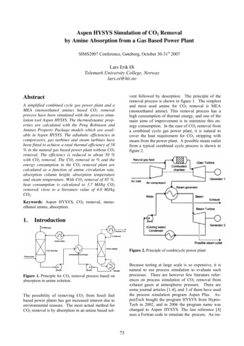
2.2. Process DescriptionA continuous scrubbing system is used to separate CO2 from a gaseous stream. The system consists oftwo main elements, an absorber, where CO2 is absorbed into a sorbent and a regenerator (or stripper),where CO2 is released (in concentrated form) and the original sorbent is recovered. Chemical absorptionsystems tend to be more efficient than the other systems shown in Appendix A, as the process isaccompanied by a chemical reaction that enhances the overall mass transfer from gas phase to liquidphase.In a power plant application (Figure 5) cooled flue gases flow vertically upwards through the absorbercountercurrent to the absorbent (MEA in a water solution, with some additives). The MEA reactschemically with the CO2 in the flue gases to form a weakly bonded compound (carbamate). The scrubbedgases are then washed and vented to the atmosphere. The CO2-rich solution leaves the absorber andpasses through a heat exchanger, then further heated in a reboiler using low-pressure steam. The weaklybonded compound formed during absorption is broken down by the application of heat, regenerating thesorbent, and producing a concentrated CO2 stream. The hot CO2-lean sorbent is then returned to the heatexchanger, where it is cooled, then sent back to the absorber. Some fresh MEA is added make up forlosses incurred in the process.CO 2 lerAbsorberlean - coolFanrich - coolCoolerRegeneratorHEx *rich -hotPumpReboilerlean - hotFlue Gas*Cross Heat -ExchangerPumpMEAReclaimerReclaimer BottomsFigure 5. Flow Sheet for CO2 Capture from Flue Gases using Amine-based SystemThe CO2 product is separated from the sorbent in a flash separator, and then taken to the drying andcompression unit. It is compressed to very high pressures (about 2000 psig) so that it is liquefied andeasily transported to long distances to the designated storage or disposal facility.Integrated Environmental Control Model - Technical Documentation 11
2.3. Process ChemistryThe process chemistry is complex, but the main reactions taking place are [26]CO2 Absorption: 2 R-NH2 CO2 R-NH3 R-NH-COOMEA Regeneration: R-NH-COO- R-NH3 (Heat) CO2 2 R-NH2Pure MEA (with R HO-CH2CH2) is an “unhindered” amine that forms a weakly bonded intermediatecalled “carbamate” that is fairly stable. Only half a mole of CO2 is absorbed per mole of amine, as shownin the CO2 absorption equation above. On application of heat, this carbamate dissociates to give backCO2 and amine sorbent, as shown in the second equation above. Since the carbamate formed duringabsorption is quite stable, it takes lot of heat energy to break the bonds and to regenerate the sorbent.For other “hindered” amines (e.g., where R is a bulky group), the carbamate formed is not stable, and analternate reaction leads to formation of bicarbonate ions and hence a higher theoretical capacity of onemole of CO2 per mole of amine, as shown in the CO2 absorption equation below (Hezorg et al., 1997;Sartori, 1994).CO2 Absorption: R-NH2 CO2 H2O R-NH3 HCO3MEA Regeneration: HCO3- R-NH3 (less Heat) CO2 H2O R-NH2The regeneration of these amines requires lesser amount of heat energy as compared to the unhinderedamines. But the CO2 uptake rate of hindered amines is very low. Efforts are underway to formulatebetter sorbents by combining favorable properties of these two groups of amines.2.4. Process EquipmentThe CO2 capture and separation system consists of the following capital equipmentDirect contact cooler: The flue gases coming out of a power plant are quite hot. The temperature of fluegas may be ranging from as low as 60 deg. C (in case of coal-fired power plants with wet SO2 scrubbers)to more than 550 deg. C (in case of natural gas fired simple cycle power plants). It is desirable to cooldown the flue gases to about 45-50 deg. C, in order to improve absorption of CO2 into the amine sorbent(the absorption being an exothermic process is favored by low temperatures), to minimize sorbent losses(higher temperature may lead to sorbent losses due to evaporation and degradation), and to avoidexcessive loss of moistur
IECM Technical Documentation: Amine-based Post-Combustion CO 2 Capture Prepared by: The Integrated Environmental Control Model Team Department of Engineering and Public Policy