Transcription
OO Analysis and Designwith UML 2 and UPDr. Jim Arlow,Clear View Training Limited Clear View Training 2010 v2.61
Introduction Clear View Training 2010 v2.62
About you Name?Company?What are you working on?Previous experience of OO?Previous experience of modelling?One thing you hope to gain from this course?Any hobbies or interests? Clear View Training 2010 v2.63
Structure of this courseOO Analysis andDesign with UMLand absDesign Clear View Training 2010 v2.6ImplementationSummary4
Guiding principles This course uses the Unified Software DevelopmentProcess (UP) to define the activities of OO analysisand design using UMLThe UP is the industry standard software engineeringprocess for the UML Clear View Training 2010 v2.65
xrefCourse materialsHandoutsLabsSolutionsISBN:0321321278 For easy reference, all slides in this course are crossreferenced to sections in the course book "UML 2 andthe Unified Process" There is an example cross reference icon in the top left handcorner of this slide Clear View Training 2010 v2.66
Labs This is a practical course, and there is a lot oflaboratory workOur approach to this work is cooperative rather thancompetitive Work togetherAsk each other for helpShare ideas and experienceDon’t get bogged down! If something brings you to a halt for more than 10 minutes,then ask for help Clear View Training 2010 v2.67
Goals of the course To provide a thorough understanding of OOanalysis and design with UMLTo follow the process of OO analysis anddesign from requirements capture through toimplementation using the Unified SoftwareEngineering Process as the frameworkTo have fun! Clear View Training 2010 v2.68
Conditions of satisfaction You will know you are succeeding when: You can read and understand UML diagramsYou can produce UML models in the laboratoryworkYou apply your knowledge effectively back at yourworkplaceQuestions: You can ask questions at any time!Your participation is always valued Clear View Training 2010 v2.69
Summary That’s the end of the introduction so on withthe course! Clear View Training 2010 v2.610
UML principles Clear View Training 2010 v2.611
1.2What is UML? Unified Modelling Language (UML) is a generalpurpose visual modelling language Can support all existing lifecyclesIntended to be supported by CASE toolsUnifies past modelling techniques and experienceIncorporates current best practice in softwareengineeringUML is not a methodology! UML is a visual languageUP is a methodology Clear View Training 2010 v2.612
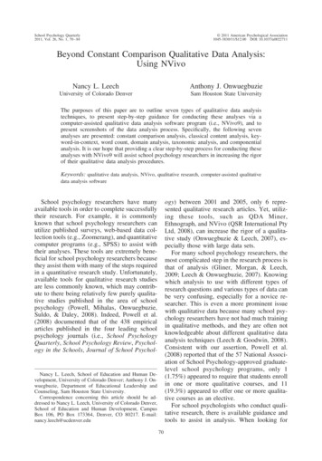
1.3UML acobson(Objectory)Coad/Yourdon Fusion1st unificationattemptUMLwork beginsObjectManagementGroup RFPUML proposalaccepted byOMG1994199519961997OMT, Booch, CRCBooch &Rumbaugh(OMT) omesan industrystandardUML 1.xUML 2.020032004Ongoing UML developmentA major upgrade to UML at the end of 2003: Greater consistencyMore precisely defined semanticsNew diagram typesBackwards compatible Clear View Training 2010 v2.613
1.4UML future? The future of development of UML will be increasinglyaffected by Model Driven Architecture cModelgenerateCodedeploy Clear View Training 2010 v2.614
1.5Why "unified"? UML is unified across several domains: AcrossAcrossAcrossAcrossAcrossAcrosshistorical methods and notationsthe development lifecycleapplication domainsimplementation languages and platformsdevelopment processesinternal concepts Clear View Training 2010 v2.615
1.6Objects and the UML UML models systems as collections of objectsthat interact to deliver benefit to outside usersStatic structure What kinds of objects are importantWhat are their relationshipsDynamic behaviour Lifecycles of objectsObject interactions to achieve goals Clear View Training 2010 v2.616
1.7UML Structure In this section we present an overview of thestructure of the UMLAll the modelling elements mentioned here arediscussed later, and in much more detail!Building blocksCommon mechanismsArchitecture Clear View Training 2010 v2.617
1.8UML building blocks Things Relationships Modelling elementsTie things togetherDiagrams Views showing interesting collections of thingsAre views of the model Clear View Training 2010 v2.618
1.8.1Things Structural things – nouns of a UML model Behavioural things – verbs of a UML model Class, interface, collaboration, use case, active class,component, nodeInteractions, state machineGrouping things packagePackageModels, frameworks, subsystemsAnnotational things NotesTagged valuesSome Informationabout a thing Clear View Training 2010 v2.619
1.8.2RelationshipsrelationshipUML syntaxbrief semanticsdependencyThe source element depends on the target elementand may be affected by changes to it.associationThe description of a set of links between objects.aggregationThe target element is a part of the source element.compositionA strong (more constrained) form of aggregation.containmentThe source element contains the target element.generalizationThe source element is a specialization of the moregeneral target element and may be substituted for it.realizationThe source element guarantees to carry out thecontract specified by the target element Clear View Training 2010 v2.620
1.8.3UML has 13 types of diagramitalics indicates anabstract categoryof diagram typesnormal font indicates an actual type ofdiagram that you can create Structure diagrams model the structure of the system (the static model)Behavior diagrams model the dynamic behavior of the system (thedynamic model)Each type of diagram gives a different type of view of the model Clear View Training 2010 v2.621
1.8.3UML 2 diagram syntaxframeheadingcontents areaheading syntax: kind name parameters N.B. kind and parameters are optional The heading specifies the kind ofdiagram, it’s name and anyinformation (parameters) neededby elements in the diagramThe frame may be implied by adiagram area in the UML tool Clear View Training 2010 v2.6implied frame22
1.9UML common mechanisms UML has four common mechanisms that applyconsistently throughout the language: SpecificationsAdornmentsCommon divisionsExtensibility mechanisms Clear View Training 2010 v2.623
1.9.1SpecificationsBankAccounticon ormodelingelementsemantic backplanenameaccountNumberClass )DepositUse case specificationDependency specification Behind every UML modelling element is a specification which provides atextual statement of the syntax and semantics of that elementThese specifications form the semantic backplane of the model Clear View Training 2010 v2.624
1.9.2Adornments Every UML modellingelement starts with abasic symbol to whichcan be added a numberof adornments specific tothat symbolWe only showadornments to increasethe clarity of the diagramor to highlight a specificfeature of the modelWindowWindow{author Jim, status tested} size : Area (100,100)#visibility : Boolean false defaultSize: Rectangle#maximumSize : Rectangle-xptr : XWindow* create() hide() display( location : Point )-attachXWindow( xwin : XWindow*) Clear View Training 2010 v2.625
1.9.3Common divisions Classifier and instance A classifier is an abstraction, an instance is aconcrete manifestation of that abstractionThe most common form is class/object e.g. aclassifier might be a BankAccount class, and aninstance might be an object representing my bankaccountGenerally instances have the same notation asclasses, but the instance name is ate»myAccount:BankAccountbalance 100.0Interface and implementation An interface declares a contract and animplementation represents a concrete realization ofthat contractBorrowableLibraryItem Clear View Training 2010 v2.626
1.9.4Extensibility mechanismsconstraintnote{ each Tickethas a unique id } tagged valueidA stereotype allows us to define a new UML modelling element based onan existing oneWe define the semantics of the stereotype ourselvesStereotypes add new elements to the UML metamodelWritten as «stereotypeName»Constraints stereotypeStereotypes «entity»Ticket{version 1.1}Extends the semantics of an element by allowing us to add new rulesabout the elementWritten as { some constraint }Tagged values are attachedto a stereotypeAllows us to add new, ad-hoc information to an element’s specificationWritten as { tag1 value1, tag2 value2 } Clear View Training 2010 v2.627
1.9.4.2Stereotype syntax optionsstereotype namein guillemets«entity»Ticketstereotype iconTicketstereotype nameand iconstereotypedrelationship control»JobManager«call»SchedulerA stereotype introduces a new modelling element and so we must alwaysdefine semantics for our stereotypesEach model element can have many stereotypes Clear View Training 2010 v2.628
1.9.4.4UML profiles A profile customizes UML for a specificpurposesA UML profile is a collection of stereotypes,tagged values and constraints The tagged values and constraints are associatedwith stereotypesStereotypes extend one of the UML metamodel elements (e.g. Class, Association) Any element that gets the stereotype also gets theassociated tagged values and constraints Clear View Training 2010 v2.629
1.10Architecture "The organisational structure of a software system" UML specification & IEEE Std. 610.12-1990RUP has a 4 1 view of architecturesystem lityDesign viewbehaviourThe 4 1 View ofArchitecture, PhilippeKruchten, IEEE Software,12(6) Nov. 1995, p. 45-50Use case viewProcess viewDeployment viewsystem topologydistributiondeliveryinstallation Clear View Training 2010 v2.630
1.11Summary The UML is composed of building blocks: The UML has four common mechanisms: sCommon divisionsExtensibility mechanismsThe UML is based on a 4 1 view of systemarchitecture Clear View Training 2010 v2.631
Introduction to the Unified Process Clear View Training 2010 v2.632
2.2The Unified Process (UP) The Unified Software Development Process is an industry standard softwareengineering process UP is: Use case (requirements) drivenRisk drivenArchitecture centricIterative and incrementalUP is a generic software engineering process. It has to be customised(instantiated) for your project It is commonly referred to as the "Unified Process" or UPIt is the generic process for the UMLIt is free - described in "The Unified Software Development Process", ISBN:0201571692"In house standards, document templates, tools, databases, lifecycle modifications, Rational Unified Process (RUP) is an instantiation of UP RUP is a product marketed and owned by Rational CorporationRUP also has to be instantiated for your project Clear View Training 2010 v2.633
2.3UP ng atEricssonSpecification& 87JacobsonestablishesObjectory ABRationalacquiresObjectory 1199819992001OngoingRUPdevelopment2004UML becomesan industrystandard Clear View Training 2010 v2.634
2.7Iterations Iterations are the key to the UPEach iteration is like a mini-project including: get early andcontinuous feedbackWe arrive at a final product release through a sequence ofiterationsIterations can overlap - this allows parallel development andflexible working in large teams PlanningAnalysis and designIntegration and testAn internal or external releaseRequires careful planningIterations are organised into phases Clear View Training 2010 v2.635
2.7.1Iteration workflows Each iterationmay contain all ofthe coreworkflows butwith a differentemphasisdepending onwhere theiteration is in thelifecycleUP specifies 5 core estAn iterationPlanningProject specific Assessmentother workflows Clear View Training 2010 v2.636
2.7.2Baselines and increments Each iteration generates a baselineA baseline is a set of reviewed and approved artefactsthat: Provide an agreed basis for further review and developmentCan be changed only through formal procedures such asconfiguration and change managementAn increment is the difference between the baselinegenerated by one iteration and the baseline generatedby the next iteration This is why the UP is called “iterative and incremental” Clear View Training 2010 v2.637
2.8UP seIterationsIter 15 CoreWorkflows R A D ElaborationIter 2IT Iter 3 tionTransitionIter 4 Iter 5 Iter 6 Each phase can include several iterations Life-cycleArchitectureThe exact number of iterations per phase depends on the size of the project!e.g. one iteration per phase for small projectsEach phase concludes with a major milestone Clear View Training 2010 v2.638
2.9Phases and Workflows This figure is thekey tounderstandingUP!For each phasewe will consider: The focus interms of thecore workflowsThe goal for thephaseThe milestoneat the end ofthe ransitionamount of rationsI1I2 Clear View Training 2010 v2.6InIn 1In 2ImIm 139
2.9.2InceptionRequirements – establish business case andscope. Capture core requirementsamount of workin each core workflowInception ElaborationRA DIConstructionTransitionAnalysis – establish feasibilityFocusDesign – design proof of concept or technicalprototypesImplementation – build proof of concept ortechnical prototypeTest – not generally applicableGoalsEstablish feasibility of the project - create proof of concept/technical prototypesCreate a business caseScope the system - capture key requirementsIdentify critical risks Clear View Training 2010 v2.640
2.9.3Inception - milestone Life Cycle Objectives - conditions of satisfaction: System scope has been definedKey requirements for the system have been captured. Thesehave been defined and agreed with the stakeholdersAn architectural vision exists. This is just a sketch at thisstageA Risk AssessmentA Business CaseProject feasibility is confirmedThe stakeholders agree on the objectives of the project Clear View Training 2010 v2.641
2.9.4ElaborationRequirements – refine system scope andrequirementsR ADInception ElaborationConstructionITTransitionAnalysis – establish what to buildFocusDesign – create a stable architectural baselineImplementation – build the architecturalbaselineTest – test the architectural baselineGoalsCreate an executable architectural baselineRefine Risk Assessment and define quality attributes (defect rates etc.)Capture use cases to 80% of the functional requirementsCreate a plan with sufficient detail for the construction phaseFormulate a bid which includes resources, time, equipment, staff, cost Clear View Training 2010 v2.642
2.9.6Elaboration - milestone Lifecycle Architecture - conditions ofsatisfaction: A resilient, robust executable architectural baselinehas been createdThe Risk Assessment has been updatedA project plan has been created to enable a realisticbid to be formulatedThe business case has been verified against theplanThe stakeholders agree to continue Clear View Training 2010 v2.643
2.9.7ConstructionR ARequirements – uncover any requirementsthat had been missedInception ElaborationConstructionDITTransitionAnalysis – finish the analysis modelFocusDesign – finish the design modelImplementation – build the Initial OperationalCapabilityTest – test the Initial Operational CapabilityGoalsComplete use case identification, description and realizationFinish analysis, design, implementation and testMaintain the integrity of the system architectureRevise the Risk Assessment Clear View Training 2010 v2.644
2.9.9Construction - milestone Initial Operational Capability - conditions ofsatisfaction: The product is ready for beta testing in the userenvironment Clear View Training 2010 v2.645
2.9.10TransitionDRequirements – not applicableInception ElaborationConstructionITTransitionAnalysis – not applicableFocusDesign – modify the design if problems emergein beta testingImplementation – tailor the software for theuser site. Fix bugs uncovered in beta testingTest – perform beta testing and acceptancetesting at the user siteGoalsCorrect defectsPrepare the user site for the new software and tailor the software to operate at the user siteModify software if unforeseen problems ariseCreate user manuals and other documentationProvide customer consultancyConduct post project review Clear View Training 2010 v2.646
2.9.12Transition – milestone Product Release - conditions of satisfaction: Beta testing, acceptance testing and defect repairare finishedThe product is released into the user community Clear View Training 2010 v2.647
2.10Summary UP is a risk and use case driven, architecture centric, iterative andincremental software development processUP has four phases: InceptionElaborationConstructionTransitionEach iteration has five core workflows: RequirementsAnalysisDesignImplementationTest Clear View Training 2010 v2.648
Requirements - introduction Clear View Training 2010 v2.649
3.2Requirements - purpose The purpose of therequirements workflow is tocreate a high-levelspecification of what shouldbe implementedWe interview thestakeholders to find outwhat they need the systemto do for them – theirrequirementsInceptionElaboration Clear View Training 2010 v2.6ConstructionTransition50
3.3Requirements - icationpackageanchoriconUse casemodelP1P2P3use caseactor Clear View Training 2010 v2.651
3.4Requirements - workflowFind actors and use casesSystem AnalystArchitectUse case specifierUser interface designerStructure the use case modelPrioritise use casesDetail a use casePrototype user interface Clear View Training 2010 v2.652
3.4We add find functional requirementsRequirements Engineerfind non-functional requirementstrace requirements to use casesArchitect prioritise requirementsIn order to adopt a rigorous approach to requirements weneed to extend the basic UP workflow with functional andnon-functional requirements elicitation and requirementstraceability Clear View Training 2010 v2.653
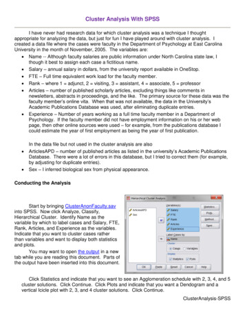
3.5The importance of requirementsProject FailuresIncomplete requirements are the primaryreason that projects fail!IncompleterequirementsLack of userinvolvementLack of resourcesUnrealisticexpectationsLack of executivesupportChangingrequirementsLack of planningDidn't need it anylongerThe Standish Group, "The CHAOS Report (1994) " Clear View Training 2010 v2.654
3.6What are requirements? Requirements - “A specification of what should beimplemented”: In UP we create a Software Requirements Specification (SRS) What behaviour the system should offerA specific property of the systemA constraint on the systemThe beginning of the OO software construction process it is a statementof the system requirements for all stakeholdersOrganises related requirements into sectionsThe SRS consists of: Requirements model comprising functional and non-functionalrequirementsUse case model comprising actors and use cases Clear View Training 2010 v2.655
3.6.2Writing requirements id The system shall function unique identifiername of systemkeywordfunction to be performede.g. "32 The ATM system shall validate the PIN number." There is no UML standard way of writing requirements! Functional Requirements - what the system should do We recommend the uniform sentence structure above"The ATM system shall provide a facility for authenticating the identity ofa system user"Non-functional Requirements - a constraint on how thefunctional requirements are implemented "The ATM system shall authenticate a customer in four seconds or less" Clear View Training 2010 v2.656
3.7The map is not the territory Everyone filters information to create theirown particular model of the world. NoamChomsky described this as three processes: these filters areappliedautomaticallyandunconsciously Deletion – information is filtered outDistortion – information is modified by the relatedmechanisms of creation and hallucinationGeneralisation –the creation of rules, beliefs andprinciples about truth and falsehoodThese filters shape natural language and sowe may need to work to recover filteredinformation Clear View Training 2010 v2.657
3.8Summary We have seen how to capture: Functional requirementsNon-functional requirementsWe have had a brief overview of the threefilters which people use to construct theirmodel of the world Clear View Training 2010 v2.658
Requirements –use case modelling Clear View Training 2010 v2.659
4.2Use case modelling Use case modelling is a form of requirementsengineeringUse case modelling proceeds as follows: Find the system boundaryFind actorsFind use cases Use case specificationScenariosIt lets us identify the system boundary, who or whatuses the system, and what functions the systemshould offer Clear View Training 2010 v2.660
4.3Find actors and use casesBusiness model[or domain model]SystemanalystRequirementsmodelFind actors anduse casesUse case model[outlined]ProjectglossaryFeature list Clear View Training 2010 v2.661
4.3.1The subject Before we can build anything, we need toknow: Where the boundary of the system liesWho or what uses the systemWhat functions the system should offer to its userssubjectSystemNameWe create a Use Case model containing: Subject – the edge of the system also known as the system boundaryActors – who or what uses the systemUse Cases – things actors do with the systemRelationships - between actors and use cases Clear View Training 2010 v2.662
4.3.2What are actors? An actor is anything that interacts directly withthe system Actors identify who or what uses the system and soindicate where the system boundary liesActors are external to the systemAn Actor specifies a role that some externalentity adopts when interacting with the system«actor»CustomerCustomer Clear View Training 2010 v2.663
4.3.2.1Identifying Actors When identifying actors ask: Who or what uses the system?What roles do they play in the interaction?Who installs the system?Who starts and shuts down the system?Who maintains the system?What other systems use this system?Who gets and provides information to the system?Does anything happen at a fixed time?Time Clear View Training 2010 v2.664
4.3.3What are use cases? A use case is something an actor needs the system to do. It isa “case of use” of the system by a specific actorUse cases are always started by an actor The primary actor triggers the use caseZero or more secondary actors interact with the use case in some wayUse cases are always written from the point of view of theactorsPlaceOrderGetStatusOnOrder Clear View Training 2010 v2.665
4.3.3.1Identifying use cases Start with the list of actors that interact with thesystemWhen identifying use cases ask: What functions will a specific actor want from the system?Does the system store and retrieve information? If so, whichactors trigger this behaviour?What happens when the system changes state (e.g. systemstart and stop)? Are any actors notified?Are there any external events that affect the system? Whatnotifies the system about those events?Does the system interact with any external system?Does the system generate any reports? Clear View Training 2010 v2.666
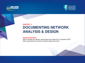
4.3.3.2The use case diagramMail Order System use case diagramMail Order Systemcommunicationrelationshipsubject namesystem mpanyCustomeractorCheckOrderStatusSendCatalogueuse case Clear View Training 2010 v2.6Dispatcher67
4.3.4The Project Glossary Project GlossaryTerm1Term2Term3 msDefinitionSynonymsHomonyms In any business domain there isalways a certain amount of jargon.It’s important to capture the languageof the domain in a project glossaryThe aim of the glossary is to definekey terms and to resolve synonymsand homonymsYou are building a vocabulary thatyou can use to discuss the systemwith the stakeholders Clear View Training 2010 v2.668
4.4Detail a use caseUse case model[outlined]Use case specifierSupplementaryrequirementsDetail ause caseUse case[detailed]Glossary Clear View Training 2010 v2.669
4.5Use case specificationUse case: PaySalesTaxuse case nameuse case identifierID: 1brief descriptionBrief description:Pay Sales Tax to the Tax Authority at the end of the business quarter.the actors involved in theuse casePrimary actors:TimeSecondary actors:TaxAuthoritythe system state beforethe use case can beginPreconditions:1. It is the end of the business quarter.Main flow:the actual steps of the usecaseimplicit time actor1. The use case starts when it is the end of the business quarter.2. The system determines the amount of Sales Tax owed to the TaxAuthority.3. The system sends an electronic payment to the Tax Authority.the system state when theuse case has finishedPostconditions:1. The Tax Authority receives the correct amount of Sales Tax.alternative flowsAlternative flows:None. Clear View Training 2010 v2.670
Naming use cases Use cases describe something that happensThey are named using verbs or verb phrasesNaming standard 1: use cases are named usingUpperCamelCase e.g. PaySalesTax1 UML 2 does not specify any naming standards.All naming standards are our own, based on industry best practice. Clear View Training 2010 v2.671
4.5.5Pre and postconditions Preconditions and postconditionsare constraintsPreconditions constrain the stateof the system before the usecase can startPostconditions constrain the stateof the system after the use casehas executedIf there are no preconditions orpostconditions write "None"under the headingUse case: PlaceOrderPreconditions:1. A valid user has logged on to thesystemPostconditions:1. The order has been markedconfirmed and is saved by the system Clear View Training 2010 v2.672
4.5.6Main flow number The something some action The flow of events lists the steps in a use caseIt always begins by an actor doing something The flow of events should be a sequence of short steps that are: A good way to start a flow of events is:1) The use case starts when an actor function DeclarativeNumbered,Time orderedThe main flow is always the happy day or perfect world scenario Everything goes as expected and desired, and there are no errors,deviations, interrupts, or branchesAlternatives can be shown by branching or by listing under Alternativeflows (see later) Clear View Training 2010 v2.673
4.5.6.2Branching within a flow: If Use the keyword if toindicate alternatives withinthe flow of events There must be a Booleanexpression immediatelyafter ifUse indentation andnumbering to indicate theconditional part of the flowUse else to indicate whathappens if the condition isfalse (see next slide)Use case: ManageBasketID: 2Brief description:The Customer changes the quantity of an item in the basket.Primary actors:CustomerSecondary actors:None.Preconditions:1. The shopping basket contents are visible.Main flow:1. The use case starts when the Customer selects an item in thebasket.2. If the Customer selects "delete item"2.1 The system removes the item from the basket.3. If the Customer types in a new quantity3.1 The system updates the quantity of the item in the basket.Postconditions:None.Alternative flows:None. Clear View Training 2010 v2.674
4.5.6.4Repetition within a flow: For We can use thekeyword For toindicate the start of arepetition within theflow of eventsThe iterationexpressionimmediately after theFor statementindicates the numberof repetitions of theindented textbeneath the Forstatement.Use case: FindProductID: 3Brief description:The system finds some products based on Customer search criteria anddisplays them to the Customer.Actors:CustomerPreconditions:None.Main flow:1. The use case starts when the Customer selects "find product".2. The system asks the Customer for search criteria.3. The Customer enters the requested criteria.4. The system searches for products that match the Customer's criteria.5. For each product found5.1. The system displays a thumbnail sketch of the product.5.2. The system displays a summary of the product details.5.3. The system displays the product price.Postconditions:None.Alternative flows:NoProductsFound Clear View Training 2010 v2.675
4.5.6.5Repetition within a flow: While We can use thekeyword while toindicate thatsomethingrepeats whilesome Booleancondition is trueUse case: ShowCompanyDetailsID: 4Brief description:The system displays the company details to the Customer.Primary actors:CustomerSecondary actors:NonePreconditions:None.Main flow:1. The use case starts when the Customer selects "show company details".2. The system displays a web page showing the company details.3. While the Customer is browsing the company details4. The system searches for products that match the Customer's criteria.4.1. The system plays some background music.4.2. The system displays special offers in a banner ad.Postconditions:1. The system has displayed the company details.2. The system has played some background music.3. The systems has displayed special offers.Alternative flows:None. Clear View Training 2010 v2.676
4.5.7Branching: Alternative flows We may s
The Unified Software Development Process is an industry standard software engineering process It is commonly referred to as the "Unified Process" or UP It is the generic process for the UML It is free - described in "The Unified Software Development Process", ISBN:0201571692" UP is: Use case (requirements) driven Risk driven