Transcription
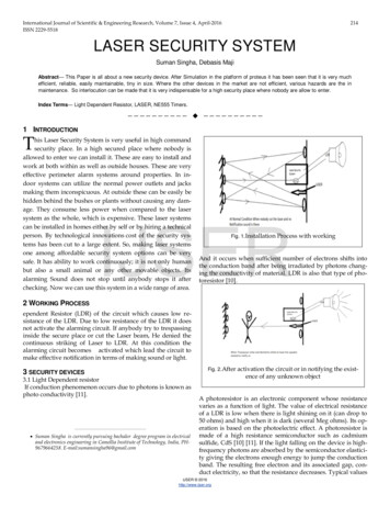
Compact and innovative laser beam steering opticalengine for smart glasses applications.Alex DOMNITS, Shlomy ERLICH, Dadi SHARON, Elan ROTHSTMicroelectronics LTD. (Israel)ABSTRACTSmart Glasses, a subcategory of Head Mounted Display devices, are getting popular in the recentyears, offering a convenient way to add information in addition to what the wearer see. Designers areseeking ways to build a Display Engine that can meet the targeted image performance (such asresolution, filed of view) yet keeping the total device size and weight as low as possible. This paperpresents an innovative Display Engine based on Laser Beam Scanning (LBS) and outlines the mainbuilding blocks that were design and prototyped. It presents the use of MEMS Micro Mirrors (Resonantmirror and Linear mirror) and a newly developed RGB laser light source that integrates the three laserdiodes into a single package. This paper outlines the opto-mechanical design considerations, beamand spot size analysis, the driving electronics, mirror and color control loops, the procedures and stepsto assemble and calibrate the optical engine and finally presents the achieved results of this work.Keywords: MEMS micro mirrors, RGB package 3 in1 light source.1. SHORT HISTORYMobile Projection at ST dates back to 2008 when an Israeli startup called bTendo, that was later onacquired by ST, developed the one of the first laser based pico-projector, using ST’s MEMS scanningmirrors.Since then, MEMS and laser diodes technologies have evolved, and more efficient mirrors and laserscame to market. The increase of laser diodes emitted optical power enabled to project a higher degreeof luminosity while decreasing the overall dimensions of the optical module. This enabled ST the greatopportunity to open up new markets such as augmented reality and smart glasses, requiring a powerefficient and compact display engine. During the recent years, another important breakthrough tookplace with the availability of new piezo actuated micro mirrors and a compact 3 in 1 RGB laser package,further decreasing the overall engine size and weight.2008bTendo - MEMS ScannerCurrent volume - 4cc2009bTendo - MEMS ScannerCurrent volume – 2.3cc20122010bTendo - MEMS ScannerCurrent volume – 2.1ccST - MEMS ScannerCurrent volume – 1.7ccFigure 1: Laser Based Optical Engine Evolvement2. INTRODUCTIONProc. Of SPIE STM Paper 11697-242021ST- MEMS ScannerCurrent volume – 0.65cc
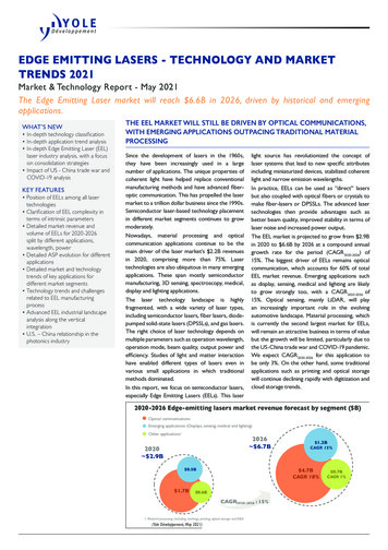
The optical engine (OE) is a laser-based MEMS raster scanning projector. The module is built from twomain subassemblies integrated together. The upper base includes the RGB laser light source withcollimating optics and the linear (quasi-static) slow scanning mirror. The lower base includes theresonance fast scanning mirror. The module is controlled by dedicated electronics that essentiallymodulates the lasers and drives and controls the mirrors.The Electronics subsystem includes: Digital Controller - Responsible for video processing, geometric distortion compensation,mirrors control loop, Laser Diode Driver modulation, temperature and pressure compensation. Laser Diode Driver – Driving the lasers with appropriate electrical current to generate the rightcolor balance per projected spot. MEMS Driver – Drives the MEMS mirrors with right voltage in order to keep the mirrorswinging at the appropriate frequency and opening angle.The Optical Engine subsystem includes: Lasers – That emit light in the visible RGB spectrum. Optics and relay optics – For beam shaping, collimation and combing. Power Detector – Used to calibrate the lasers’ power during operation. MEMS Mirrors – Scan the light to project a two-dimensional image.The above subsystems are synchronized and controlled by dedicated processor and firmware.Figure 2: Compact and innovative laser beam scanning optical engine and driving electronics.As mentioned, one of the main goals is to significantly reduce the form factor of the optical engine. Inthe following chapters we will go over the key design elements that enabled us to achieve this goal.3. OPTICAL ENGINE CHARACTERISATIONRGB laser diodes 3 in 1 packageEach emitter of the RGB laser package emits a divergent light that is reflected by an integrated reflectivefolding prism and exits the package thru a sealed exit window. The use of this innovative light sourcepackage allowed us to significantly reduce the form factor of optical engine without compromising onthe laser power. The use of a packaged RGB laser module compared to the previously use of threeseparate laser diodes packaged in a standard TO CAN significantly reduced the overall volume, asseen in the below image.Proc. Of SPIE STM Paper 11697-24
Figure 3: comparison between: a) TO38, b) RGB 3 in 1 packageWhat is MEMS µMirror ScannerA MEMS micro mirror or scanner is a tiny reflective mechanical device that swings at a givenfrequency and opening angle. By using collimated laser light source (visible and invisible), light canbe steered and spatially modulated (MEMS Scanner). Various applications can benefit from usingMEMS scanners thanks to the miniaturization and power efficient technology. There are severalactuation technologies that can be used for generating the required force to move the mirror. Suchactuators include Electro Magnetic, Piezo based and electrostatic actuators. Specifically, in thispaper we have considered the use of an electrostatically actuated mirror that consists of two mainparts: The torsional spring and a comb drive. Careful design keeps stress levels in a safe range forlong term operation.Figure 4: Mechanical structure of a torsional spring and a staggered comb drive fingers.Beam scanningThe laser beam is scanned using two uniaxial mirrors, each swinging in one dimension. TheHorizontal mirror (aka fast scanner) swings from left to right (and back) in a sinusoidal motion, andby the Vertical mirror (aka slow scanner) swings from top to bottom (and back, known as retrace orblanking) in a linear motion. The combination of the two movements generates a nonlinear “rasterscan” that ends in a trapezoidal distorted image. In order to have a rectangular projection only partof the scanned area is used for the projection (active area). A geometrical engine compensates forany geometrical distortion. Additionally, during the retrace the lasers are turned off. Retrace istypically 10% of the total duty cycle.Raster scanning geometryProc. Of SPIE STM Paper 11697-24
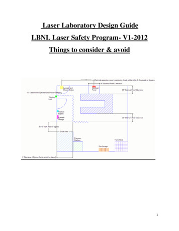
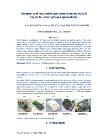
The system is configured to have an odd number of scan lines: Every frame the beam’s startingposition changes. It is scanned from top left corner for the Odd Frames and top right corner for theEven Frames. Interlacing the even and odd scanned frames ensures a full “coverage” of theprojection area. The figure below depicts the scanning methodology and the geometrical distortion.Scan from R to LScan from L to RODD FRAMEEVEN FRAMEFigure 5: Raster scanningThe Image is rastered pixel by pixel, or more accurately spot by spot. The color of each pixel isconstructed by the combined RGB lasers. The position to project the combined laser beam spot iscontrolled by the resonant (Horizontal) and linear (Vertical) mirrors (2 x uni-axial). The Horizontalmirror (Fast axis) scans at a high frequency (21Khz) all columns of the image line, while the Verticalmirror (Slow axis, frame rate 60Hz) scans the complete line onto the projection surface. Theresolution (partially) is determined by the Horizontal mirror frequency, opening angle and diameter,while the refresh rate is determined by the Vertical mirror drive frequency.Vertical MirrorHorizontal MirrorFigure 6: Laser Scanning PrinciplesOptical engine controller functionalitiesThe Color & Brightness control mechanism sets the brightness, brightness uniformity that ought tobe adjusted due to the varying velocity of the fast scanner and the Gamma Correction. Additionally,this mechanism includes temperature compensation algorithms that adjusts the emitted opticalpower in order to compensate for the possible drift of the laser power and keep the white pointstable.Closed loop operation:Both the fast and slow scanner require a closed loop driving mechanism in order to keep the:frequency and opening steady despite environmental conditions effects.Proc. Of SPIE STM Paper 11697-24
The resonant mirror uses a phase lock algorithm to assure high stability in maximum tilting angleand sinusoidal motion. The vertical mirror, which is actuated with a saw-tooth drive, requires a selfresonance cancellation algorithm to avoid artifacts during the projection.Optical ray tracingThe below ray tracing diagram represents the optical path of our system. The laser divergent lightthat is produced by RGB package is collimated by dedicated lenses and goes thru beam combinerstoward folding mirror, then reflected to resonance mirror. At this stage there it is important to keepthe spot size as such that it does not exceed the clear aperture dimensions of the resonant mirror(clear aperture is around 1mm diameter) so we do not introduce any parasitic stary light that couldbe reflected from the static mirror surfaces, such as the spring or cavity. When the system isworking, the resonant mirror is moving and producing horizontal scanned line that is reflectedtoward the vertical mirror. The linear mirror has much bigger clear aperture compared to thehorizontal one, so the scanned line is positioned correctly and symmetrically on the linear mirrorwhen the lens alignment is done accurately. The reflected line from the linear mirror propagatesexits the optical engine thru the exit window and onto the desired target such as the glass of a smartglasses device. When both mirrors are in motion, a 2D image with targeted field of view is projected.The figure below illustrates the optical path and laser beam ray trace.Figure 8: Optical ray tracingOptical design considerationsThe use of MEMS micro mirror requires an accurate optical design in order to work properly. MEMSmicro mirrors are commonly used in diffraction-limited systems, therefore the optical requirements aredependent on the electro-mechanical ones: for example, the projected resolution depends on the mirrordiameter, maximum optical scanning angle, laser emitter divergence and wavelength of the light. Figure9 shows the footprint of the laser spot on the scanning mirror. In order to have an efficient optical pathit is highly important to ensure that the laser spot will fit within the mirrors’, as well as any other, opticalcomponents’ clear aperture.number of projected pixelsN max optical scanning angle laser divergence projected wavelength mirror diameter propotionalProc. Of SPIE STM Paper 11697-24
Figure 9: Simulated laser spot footprint on the mirror surfaceThe Optical Engine key componentsBesides the MEMs mirrors (Horizontal & Vertical) that are assembled in a predefined angle one to theother, the optical engine contains the laser light source as well as additional optical and electricalcomponents.The light source is based on OSRAM’s RGB laser package that consists of several laser diode emitters:Red - 637nm, Green 520nm and Blue 445nm for RGB applications and a collimation lens per eachemitter. The main purpose of this lens in our system is to collect the divergent light from LD emitter andto collimate it to a specific focal plane distance (application dependent).In our system we used Plano-Convex lens with an NA of 0.38, EFL 2mm and 1mm diameter of clearaperture allowing us to collect the laser beam from the RGB emitters with given divergence angles. Ananti-reflective (AR) coating is designed for 400-700nm visible spectrum and is applied to avoid straylight and increase the optical path efficiency. The rectangular shape of the lens housing allow us easiermanipulation during the optical alignment. Alternatively, we can use a custom aspherical lens for evenbetter optical performance.Two possible configurations are considered for Beam Combining. The first consists of beam combiningand splitting prism and the second consists of three separate dichroic beam plates.Additionally, Polarization optics are needed in order to change or rotate the linearly polarized laserdiode light. Possible optical components that can be used for this purpose are half wave or/and quarterwave plates. An Exit window is mounted as a protective element to seal the module against particles.A Photo diode power detector and half ball lens is used to collect some of the lasers light, so properlasers power calibration and monitoring can be used by the color control loop to ensure the stability ofthe white point.4. Assembly, Alignment process & CalibrationAssembly process:The optical engine requires active alignment of three individual lenses by positioning the lenses andhardening the glue with UV light. The MEMs mirror block consists of two MEMs mirrors that requirewire bonding (gold wire). Acceptable technologies for the design and manufacturing of the housing caninclude, but are not limited to, MIM (metal injection molding), Polymer Injection Molding, Sheet metalstamping or pressing. The selected technology must comply with the required volume, tolerances andmanufacturing constraints per the targeted cost and performance.During the alignment process, the spot size and the spot shape are measured by using adequatemeasurement tools. Special consideration are given to the spot geometry and diffractions.Once the basic alignment is done the horizontal mirror is opened to obtain an horizontal scan line andthen we fine tune the lens alignment by balancing the right/left edges of the scanned line. Also, weconsider vertical balancing of the scanned line by moving the lens in Y direction.E pattern test patterns are used to monitor the sharpness of the projected image and further fine tuningis conducted to ensure proper focusing.Fine tuning adjustmentThe spot is adjusted in the center of the image field of view. This adjustment can lead to defocusedimage at the edges. By looking at the projected line as generated by the horizontal mirror,defocusing/widening of line is observed on the edges. The fine-tuning adjustment goal is to produce thethinnest and uniform line as possible by measuring and optimizing center vs. left and right edges of theprojected line. Spot adjustment and optimization of the collimation lenses is considered on three axes.Once we are done with above optimization, the lens is glued with UV adhesive.Proc. Of SPIE STM Paper 11697-24
The line should look uniform across the entireformat (center and edges)The line after spot adjustmentThe line at the edgesCenter of imageThe line at the edgesb) E-pattern after fine tuning adjustmenta) E-pattern. Defocused image at the edgesFigure 10: Fine tuning adjustment: a) before adjustment b) after adjustmentColor offset alignment process:The color offset between all three laser spots is kept to the minimal in order to support the best imagequality and which typically are within 0.2-0.5deg. Once all three lenses are aligned and glued, weperform measurements with a beam analyzing camera to capture and measure the spot parametersand a power meter to measure the optical power. The Optical Engine cover is glued at the end of thealignment process with UV adhesive. The system is passed to system integration and calibration as thenext step.Target offset betweenspots 0.5degOffset between spots 0.5degGRBGRb)a)BFigure 11: laser spot adjustment: a) incorrect, b) correctSpot size analysis:The laser beam can be collimated, by using the collimation lenses, to different focal plane distances(FPD) from near field to infinity. This process is done by manipulating the lenses in five mechanicalaxes (x, y, z lateral movement and x/y tilts) against the light source. The typical spot size at far field(1.5m) when using long distance collimation as FPD (green laser as an example) is about2.1x1.6mm. The typical spot size at near field (30mm) when using short distance collimation asFPD (green laser as an example) is about 0.15x0.1mm. When the alignment is performed optimally,the center of gravity of the Gaussian beam is well centered which allows us to keep the best opticaland imaging performance of the overall system. The system is passed to system integration andcalibration as the next step after all measurements are done.FPD1500mm- 2.1X1.6mmProc. Of SPIE STM Paper 11697-24
Figure 12: a) center of gravity, b) laser spot sizeSystem calibration:Once all optical alignments are done, the Optical Engine goes through two calibrations procedures.The first calibration procedure handles the lasers power, luminosity and white balancing. Thesecond calibration procedure handles the MEMS mirror related parameters and includeGeometrical distortion correction of the projected image, the horizontal and vertical field of view andaspect ratio of the image as well as the color brightness and uniformity. The figures below showsthe calibration stations.Figure 13: Laser power calibration setupFigure 14: Mirrors calibration setup5. Conclusion and future workThe purpose of this study was to design, prototype and characterize a compact and innovative laserbeam scanning optical engine based on ST’s MEMS Micro mirrors for smart glasses applications.Proc. Of SPIE STM Paper 11697-24
As observed, an ultra-small engine capable of generating color images at high resolution andsharpness was achieved.Future work could explore possible designs and technology to achieve higher resolution opticalsystems (such as by multiplying the number of RGB sets), the integration of more advanced beamcombiners (such as Planar Light Circuit) and the integration of few optical elements for further sizeand wight reduction.6. REFERENCES1. mgfsub2sub-coated-planoconvex-lens/19905/Proc. Of SPIE STM Paper 11697-24
The position to project the combined laser beam spot is controlled by the resonant (Horizontal) and linear (Vertical) mirrors (2 x uni-axial). The Horizontal . Red - 637nm, Green 520nm and Blue 445nm for RGB applications and a collimation lens per each emitter. The main purpose of this lens in our system is to collect the divergent light from .