Transcription
FUSB380C Product PreviewAutonomous USB Type-CPassive Cable MarkerDescriptionwww.onsemi.comThe FUSB380C provides a small footprint solution for passivecable applications. 28 V Tolerant VCONN and CC provides VBUSshorting protection. One FUSB380C can be used in a VCONNthrough Type C cable application or two FUSB380Cs can be used ineach plug avoiding the high cost of routing VCONN through theType C cable. The FUSB380C offers industry leading VCONNoperating range down to 2.4 V.WLCSP12CASE 567VZFeatures Integrated USB PD 3.0 Protocol Layer and Device Policy Engines5x Programmable for Different Cable ConfigurationsUSB PD 2.0 and 3.0 CertifiedRobust Design Features: 28 V Tolerant CC and VCONN Integrated Isolation Between VCONN1 and VCONN2 2.4 V 5.5 V VCONN OperationField Programmable for Different Cable ConfigurationsSOP’ Signaling SupportAutomatic Ra Weakening to Reduce Power Consumption12 Pin WLCSP (1.21 mm x 1.67 mm)These Devices are Pb Free, Halogen Free/BFR Free and are RoHSCompliantApplicationsMARKING DIAGRAMH6KKXYZH6KKXYZ Two Digit Device Code Two Digit Lot Run Code (&K) Two Digit Date Code (&2) Assembly Plant Code (&Z)ORDERING INFORMATIONSee detailed ordering and shipping information on page 2 ofthis data sheet. Passive CablesThis document contains information on a product under development. ON Semiconductorreserves the right to change or discontinue this product without notice. Semiconductor Components Industries, LLC, 2017May, 2019 Rev. P11Publication Order Number:FUSB380C/D
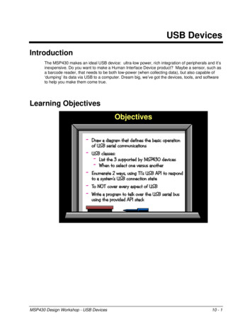
FUSB380CTable 1. DEVICE ORDERING INFORMATIONDeviceFUSB380CUCXTop MarkingTemperature RangePackageShipping†H6 40 C to 85 CWLCSP12(Pb Free)3000 / Tape & Reel†For information on tape and reel specifications, including part orientation and tape sizes, please refer to our Tape and Reel PackagingSpecifications Brochure, BRD8011/D.Table 2. 12 BALL WLCSP PIN DESCRIPTIONPin#NameA1T1Test Pin FloatA2NCNo ConnectA3GNDB1T2Test Pin FloatB2T4Test Pin – FloatB3T6Test Pin – FloatC1T3Test Pin FloatC2T5Test Pin FloatC3CCConfiguration Channel (28V NN Power (28V Tolerant)GroundVCONN Power (28V Tolerant)123AT1NCGNDBT2T4T6Top through viewCT3T5CCDVCONN2GNDVCONN1Top ViewFigure 1. 12 Ball WLCSP Top Through Viewwww.onsemi.com2
FUSB380CTable 3. MAXIMUM RATINGSSymbolParameterVCCXCC and VCONNx pins (Note 1)TJMaximum Junction TemperatureTSTORAGETLConditionsMinTyp 0.5Storage Temperature Range 65Lead Temperature (Soldering 10 Seconds) (Note 2)ESDHuman Body Model, JEDEDC JESD22 A114IEC61000 4 5, Surge ProtectionUnits28V 150 C 150 C 260Connector Pins (CC, VCONNx)4.5Others2All Pins2Connector Pins (CC, VCONNx)32Charged Device Model, JEDEC LESD22 C101SurgeMax CkVVStresses exceeding those listed in the Maximum Ratings table may damage the device. If any of these limits are exceeded, device functionalityshould not be assumed, damage may occur and reliability may be affected.1. Refer to ELECTRICAL CHARACTERISTICS, RECOMMENDED OPERATING RANGES and/or APPLICATION INFORMATION for SafeOperating parameters.2. For information, please refer to our Soldering and Mounting Techniques Reference Manual, SOLDERRM/DTable 4. RECOMMENDED OPERATING itsVCONN Voltage (Note 3)2.45.5VOperating Ambient Temperature 40 85 CFunctional operation above the stresses listed in the Recommended Operating Ranges is not implied. Extended exposure to stresses beyondthe Recommended Operating Ranges limits may affect device reliability.3. Programming Voltage range 4.7 V to 5.5 VDC AND TRANSIENT ELECTRICAL CHARACTERISTICS (Minimum and maximum values are at VCONNx 2.4 V to 5.5 V,TA 40 C to 85 C unless otherwise noted. Typical values are at TA 25 C, VCONNx 3.3 sCurrent ConsumptionIpd stbyBMC PD standby currentVCONN 2.4 to 5.5 Deviceattached, BMC PD active but notsending or receiving, Ra weakened.Other VCONN pin floating. CCpulled up/down/float.BASEBAND PD SYSTEMUIUnit Interval3.033.33TRANSMITTERpBitRateMaximum difference between the bit rateduring the payload and last 32 bits of preamble0.25%tEndDriveBMCTime to cease driving the line after the endof the last bit of the Frame23mstHoldLowBMCTime to cease driving the line after the finalhigh to low transition1Time before the start of the first bit of thepreamble when the transmitter shall startdriving the line 1tInterFrameGapAny PD transmission cannot be sent out before a dead time of at least tInterFrameGapfrom receiving or sending a packet25tTransmitGoodCRC response time from last transitionfollowing EOP to start of preamble of GoodCRC25Rise ns
FUSB380CDC AND TRANSIENT ELECTRICAL CHARACTERISTICS (Minimum and maximum values are at VCONNx 2.4 V to 5.5 V,TA 40 C to 85 C unless otherwise noted. Typical values are at TA 25 C, VCONNx 3.3 75WTRANSMITTERtFallFall Time300vSwingBMC voltage swing1.05zDriverTX output impedance at 750 kHz with anexternal 220 pF or equivalent loadns33RECEIVERcReceiverReceiver capacitance when driver isn’tturned on (Note 4)zBmcRxReceiver Input Impedance (cannot be testedbut can be simulated and guaranteed by design)1MWTransitions count in a time window of 20 msmax.3edgesnsnTransitionCountVrms 0.371; Vdc 0.5V; Freq. 1MHz25pFtRxFilterRx bandwidth limiting filter (Note 4)100tTransitionWindowTime window for detecting non idle1220msPowered Cable Termination before VCONNPower8001200W1822kWTYPE C PHYRARA WEAKzOPENWeakened RA when VCONN is appliedVCONN VVCONN RA WEAK aftertVCONNStable (min)CC resistance when VCONNx is valid andwhen VCONNx 0 V126kWUSB PD SPECIFIC TIMING PARAMETERStBISTContModetTransmitBIST Carrier Mode 2 pattern sent only forthis length of time30From receiving a packet, we have to send aGoodCRC in response within tTransmit time.It is measured from the last bit of the EOP ofthe received packet to the first bit sent of thepreamble of the GoodCRC packet60ms195ms50ms2.4V230ms800mV2.4VCABLE MARKER SPECIFICtVCONNStableThe time between the application of VCONNuntil SOP’ and SOP” shall be ready for communication.VCONN 2.4 V10VVCONN RA WEAK Voltage threshold when RA WEAK is presented after tVCONNStabletVCONNDischargeThe time from the point that the cable is detached until vVCONNDischarge shall be met.vVCONNDischargeThe VCONN voltage following cable detachand self discharge.vVCONNDisconnectThreshold used to detect VCONN disconnect.Cable loading 10 mF, RA WEAK0.8Product parametric performance is indicated in the Electrical Characteristics for the listed test conditions, unless otherwise noted. Productperformance may not be indicated by the Electrical Characteristics if operated under different conditions.4. Guaranteed by Design. Characterized on the ATE or Bench.www.onsemi.com4
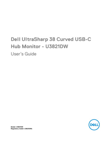
FUSB380CProduct Block DiagramFUSB380CVCONN2VCONN1VoltageRegRACCPD PHYRAPD FSMGNDFigure 2. Block DiagramApplication DiagramsFigure 3. One eMarker and VCONN Through CableFigure 4. Two eMarkers, no VCONN Through Cablewww.onsemi.com5
FUSB380CFunctional BehaviourVCONN TerminationsField Programmable FunctionThe FUSB380C device presents a RA terminationwhenever the VCONNx pins are unpowered. Only theVCONNx pin that has a voltage in the valid range fortVCONNStable will be weakened to RA WEAK.The function of RA WEAK is to discharge the voltage onVCONN to VVCONNDischarge within a maximum time oftVCONNDischarge and a maximum load of 10 mF. TheRA WEAK termination will be applied until VCONN voltagedrops below the VRAReconnect threshold. Once this thresholdis crossed RA is reapplied.The FUSB380C can be programmed by the customer viaVendor Defined Messages. The user can re program thedevice a maximum of 5 times.The device’s Discover Identity response can be fullycustomized for Passive cables, with or without Modalsupport.The FUSB380C also offers the ability to program a SerialNumber that can be read via a VDM Specific command.Table 5. SUMMARY OF FIELD PROGRAMMABLE BITSParameterDescription# of BitsID HEADERMEM USB HOST1MEM USB DEV1MEM PROD TYPEMEM MODALProduct Type3Modal Operation1MEM ID RSVD B25 23Reserved3MEM ID RSVD B22 16Reserved7USB Vendor ID16XID32USB PID16bcdDevice16MEM HW VERHardware Version4MEM FW VERFirmware Version4MEM VIDCERTIFICATION STATUS VDOMEM XIDPRODUCT VDOMEM USB IDMEM bcdDeviceCABLE VDOMEM VDO VER3MEM CABLE RSVD B20MEM TYPEC TO XMEM CABLE RSVD B17Reserved1USB Type C to X2Reserved1Cable Latency4Cable Termination Type2MEM CABLE VDO BIT10 9Max VBUS V2MEM CABLE VDO BIT8 7SS Direction2VBUS Current Handling2VBUS Through Cable1SOP2 Present1USB SS Signaling3SVID0 VID0SVID116MEM LATENCYMEM TERM TYPEMEM VBUS AMPSMEM VBUS THROUGHMEM SOP2MEM SS SIGDISCOVER SVID RESPONSESVID0MEM SVID1DISCOVER MODES VDOMEM VDO SVID0MEM VDO SVID132Mode VDO for SVID1 (Alternate Mode)www.onsemi.com632
FUSB380CTable 5. SUMMARY OF FIELD PROGRAMMABLE BITSParameterDescription# of BitsSERIAL NUMBERSMEM CABLE SNCable Serial Number136Serial numbers replied in SVIDx0 SVID01 SVID11Customer Serial Number SVID specific command5Die Serial Number SVID specific command5MEM SN SVIDMEM SN COMMANDMEM DIESN COMMANDwww.onsemi.com7
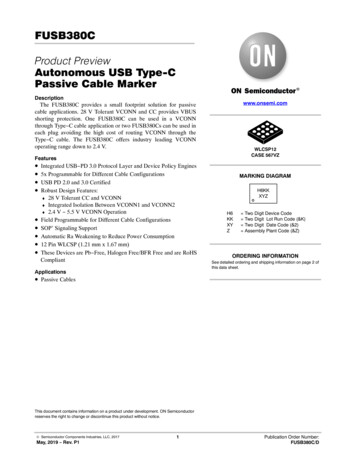
MECHANICAL CASE OUTLINEPACKAGE DIMENSIONSWLCSP12, 1.21x1.67x0.586CASE 567VZISSUE ODOCUMENT NUMBER:DESCRIPTION:98AON83933GWLCSP12, 1.21X1.67X0.586DATE 09 FEB 2018Electronic versions are uncontrolled except when accessed directly from the Document Repository.Printed versions are uncontrolled except when stamped “CONTROLLED COPY” in red.PAGE 1 OF 1ON Semiconductor andare trademarks of Semiconductor Components Industries, LLC dba ON Semiconductor or its subsidiaries in the United States and/or other countries.ON Semiconductor reserves the right to make changes without further notice to any products herein. ON Semiconductor makes no warranty, representation or guarantee regardingthe suitability of its products for any particular purpose, nor does ON Semiconductor assume any liability arising out of the application or use of any product or circuit, and specificallydisclaims any and all liability, including without limitation special, consequential or incidental damages. ON Semiconductor does not convey any license under its patent rights nor therights of others. Semiconductor Components Industries, LLC, 2019www.onsemi.com
onsemi,, and other names, marks, and brands are registered and/or common law trademarks of Semiconductor Components Industries, LLC dba “onsemi” or its affiliatesand/or subsidiaries in the United States and/or other countries. onsemi owns the rights to a number of patents, trademarks, copyrights, trade secrets, and other intellectual property.A listing of onsemi’s product/patent coverage may be accessed at www.onsemi.com/site/pdf/Patent Marking.pdf. onsemi reserves the right to make changes at any time to anyproducts or information herein, without notice. The information herein is provided “as is” and onsemi makes no warranty, representation or guarantee regarding the accuracy of theinformation, product features, availability, functionality, or suitability of its products for any particular purpose, nor does onsemi assume any liability arising out of the application or useof any product or circuit, and specifically disclaims any and all liability, including without limitation special, consequential or incidental damages. Buyer is responsible for its productsand applications using onsemi products, including compliance with all laws, regulations and safety requirements or standards, regardless of any support or applications informationprovided by onsemi. “Typical” parameters which may be provided in onsemi data sheets and/or specifications can and do vary in different applications and actual performance mayvary over time. All operating parameters, including “Typicals” must be validated for each customer application by customer’s technical experts. onsemi does not convey any licenseunder any of its intellectual property rights nor the rights of others. onsemi products are not designed, intended, or authorized for use as a critical component in life support systemsor any FDA Class 3 medical devices or medical devices with a same or similar classification in a foreign jurisdiction or any devices intended for implantation in the human body. ShouldBuyer purchase or use onsemi products for any such unintended or unauthorized application, Buyer shall indemnify and hold onsemi and its officers, employees, subsidiaries, affiliates,and distributors harmless against all claims, costs, damages, and expenses, and reasonable attorney fees arising out of, directly or indirectly, any claim of personal injury or deathassociated with such unintended or unauthorized use, even if such claim alleges that onsemi was negligent regarding the design or manufacture of the part. onsemi is an EqualOpportunity/Affirmative Action Employer. This literature is subject to all applicable copyright laws and is not for resale in any manner.PUBLICATION ORDERING INFORMATIONLITERATURE FULFILLMENT:Email Requests to: orderlit@onsemi.comonsemi Website: www.onsemi.com TECHNICAL SUPPORTNorth American Technical Support:Voice Mail: 1 800 282 9855 Toll Free USA/CanadaPhone: 011 421 33 790 2910Europe, Middle East and Africa Technical Support:Phone: 00421 33 790 2910For additional information, please contact your local Sales Representative
FUSB380C www.onsemi.com 3 Table 3. MAXIMUM RATINGS Symbol Parameter Conditions Min Typ Max Units VCCX CC and VCONNx pins (Note 1) 0.5 28 V TJ Maximum Junction Temperature 150 C TSTORAGE Storage Temperature Range 65 150 C TL Lead Temperature (Soldering 10 Seconds) (Note 2) 260 C ESD Human Body Model, JEDEDC JESD22 A114 Connector Pins (CC, VCONNx) 4.5 kV