Transcription
Deep Underground Neutrino Experiment (DUNE)Far Detector Interim Design ReportVolume 2:Chapter -daq.texJuly 19, 2018The DUNE Collaboration
ContentsContentsiList of FiguresiiiList of Tables11 Data Acquisition System1.1 Data Acquisition (DAQ) System Overview . .1.1.1 Introduction . . . . . . . . . . . . . .1.1.2 Design Considerations . . . . . . . . .1.1.3 Scope . . . . . . . . . . . . . . . . .1.2 DAQ Design . . . . . . . . . . . . . . . . . .1.2.1 Overview . . . . . . . . . . . . . . . .1.2.2 Front-end Readout and Buffering . . .1.2.3 Front-end Trigger Primitive Generation1.2.4 Dataflow, Trigger and Event Builder .1.2.5 Data Selection Algorithms . . . . . . .1.2.6 Timing and Synchronization . . . . . .1.2.7 Computing and Network Infrastructure1.2.8 Run Control and Monitoring . . . . . .1.3 Interfaces . . . . . . . . . . . . . . . . . . . .1.3.1 TPC Electronics . . . . . . . . . . . .1.3.2 PD Electronics . . . . . . . . . . . . .1.3.3 Offline Computing . . . . . . . . . . .1.3.4 Slow Control . . . . . . . . . . . . . .1.3.5 External Systems . . . . . . . . . . . .1.4 Production and Assembly . . . . . . . . . . .1.4.1 DAQ Components . . . . . . . . . . .1.4.2 Quality Assurance and Quality Control1.4.3 Integration testing . . . . . . . . . . .1.5 Installation, Integration and Commissioning . .1.5.1 Installation . . . . . . . . . . . . . . .1.5.2 Integration with Detector Electronics .1.5.3 Commissioning . . . . . . . . . . . . .1.6 Safety . . . . . . . . . . . . . . . . . . . . .1.7 Organization and Management . . . . . . . 535373738
1.7.11.7.21.7.3DAQ Consortium Organization . . . . . . . . . . . . . . . . . . . . . . . . . . 38Planning Assumptions . . . . . . . . . . . . . . . . . . . . . . . . . . . . . . . 39High-level Cost and Schedule . . . . . . . . . . . . . . . . . . . . . . . . . . . 39Glossary41References48ii
List of Figures1.11.21.31.41.51.61.7DAQ overview . . . . . . . . . . . . . . . . . . . . . . .data acquisition (DAQ) overview . . . . . . . . . . . . .Nominal SP front-end (FE) DAQ fragment . . . . . . . .Arrangement of components in DUNE timing system . . .Arrangement of components in single-phase timing systemCUC control room layout . . . . . . . . . . . . . . . . .DAQ high-level schedule . . . . . . . . . . . . . . . . . .iii.561525263640
LIST OF TABLES0–1List of Tables1.11.21.3Important requirements on the data acquisition (DAQ) system design . . . . . . . . . . 8Pre-trigger data rates from the far detector (FD) TPCs and into DAQ front end. . . . . 9Uncompressed data rates for one SP module. . . . . . . . . . . . . . . . . . . . . . . . 10Chapter Breakout:far-detector-single-phase.texThe DUNE Far Detector Interim Design Report
Chapter 1: Data Acquisition System1–2Chapter 1Data Acquisition System1.11.1.1Data Acquisition (DAQ) System OverviewIntroductionThe DUNE far detector (FD) data acquisition (DAQ) system must enable the readout, triggering,processing and distribution to permanent storage of data from all detector modules, which includesboth their electrical time projection chamber (TPC) and optical photon detection system (PDS)signals. The final output data must retain, with very high efficiency and low bias, a record of allactivity in the detector that pertains to the recognized physics goals of the DUNE experiment.The practical constraints of managing this output requires that the DAQ achieve these goals whilereducing the input data volume by almost four orders of magnitude.The current generation of liquid argon time-projection chamber (LArTPC) DAQs, such as usedin ProtoDUNE and MicroBooNE, produce data spanning a fixed window of time that is chosenbased on the acceptance of an external trigger. The DUNE DAQ faces several major challengesbeyond those of the current generation. Foremost, it must accept data from about two orders ofmagnitude more channels and from that data it must form its own triggers. This self-triggeringfunctionality requires immediate processing of the full-stream data from a large portion of all TPCchannels with a throughput of approximately one terabyte per second per detector module. Fromthis data stream, triggers must be raised based on two very different patterns of activity. Thefirst is activity localized in a small region of one detector module, such as due to beam neutrinointeractions or the passage of relatively rare cosmic-ray muons. This activity tends to correspondto a relatively large deposition of energy, around 100 MeV or more. The second pattern that mustlead to a trigger is lower energy activity dispersed in both time and spatial extent of the detectormodule, such as due to a supernova neutrino burst (SNB).The DAQ must also contend with a higher order of complexity compared to the current generation.The FD is not monolithic but ultimately will consist of four detector modules each of 10 kt fiducialChapter Breakout:far-detector-single-phase.texThe DUNE Far Detector Interim Design Report
Chapter 1: Data Acquisition System1–3mass. Each module will implement somewhat different technologies and the inevitable asymmetriesin the details of how data are read out from each must be absorbed by the unified DAQ at its frontend. Further, each detector module is not monolithic but has at least one layer of divisions, heregenerically named detector units. For example, the single-phase (SP) detector module has anodeplane assemblies (APAs) each providing data from a number of warm interface boards (WIBs)and the dual-phase (DP) detector module has charge readout (CRO) and light readout (LRO)units associated with specific electronics crates. In each detector module, there are on the orderof 100 detector units (150 for SP and 245 for DP) and each unit has a channel count that isof the same order as that of an entire LArTPC detector of the current generation. The DUNEDAQ, composed of a cohesive collection of DAQ instances called DAQ partitions, must run ona subset of all possible detector units for each given detector module. Each instance effectivelyruns independently of all the others, however some instances indirectly communicate through theexchange of high-level trigger information. This allows, for example, each detector module to takedata in isolation. It also allows for all detector modules to contribute to forming and acceptingglobal SNB triggers, and to simultaneously run small portions – consisting of a few detector units– separately in order to debug problems, run calibrations or perform other activities while notinterfering with nominal data taking in order to maintain high uptime.Substantial computing hardware is required to provide the processing capability needed to identifysuch activity while keeping up with the rate of data. The nature of various technical, financialand physical constraints leads to the need for much of the computing hardware required for thisprocessing to reside underground, near the detector modules. In such an environment, power,cooling, space, and access is far more costly than in typical data centers.Past LArTPC and long-baseline (LBL) neutrino detectors have successfully demonstrated externaltriggering using information related to their beam. The DUNE FD DAQ will accept externalinformation on recent times of Main Injector beam spills from Fermilab. This will assure triggeringwith high efficiency to capture activity pertaining to interactions from the produced neutrinos.However, even if the DUNE experiment were interested only in neutrinos from beam spills, anexternal beam trigger alone would not be sufficient. Absent any other information, such a triggermust inevitably call for the readout of all possible data from the FD over at least one LArTPCdrift time. This would lead to an annual data volume approaching an exabyte (1018 bytes), thevast majority of which would consist of just noise. This entire data volume would have to be savedto permanent storage and then processed offline in order to get to the signals.DUNE’s physics goals of course extend beyond beam-related interactions, including cosmic-raymuons, which provide an important source of detector calibration, and atmospheric neutrino interactions, which give a secondary source from which to measure neutrino properties. Taken together,recording their activity will dominate the data rate. The DAQ must also record data with sensitivity to rare interactions (both known and hypothetical) such as nucleon decay, other baryonnumber violating processes (such as neutron-antineutron oscillation), and interactions from theproducts of SNBs as well as possibly being able to observe isolated low-energy interactions fromsolar neutrinos and diffuse supernova neutrinos.Some of these events, while rare in themselves, produce patterns of activity that can be mimicked byother higher-rate backgrounds, particularly in the case of SNBs. While the exact processes involvedChapter Breakout:far-detector-single-phase.texThe DUNE Far Detector Interim Design Report
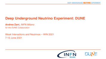
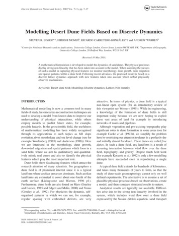
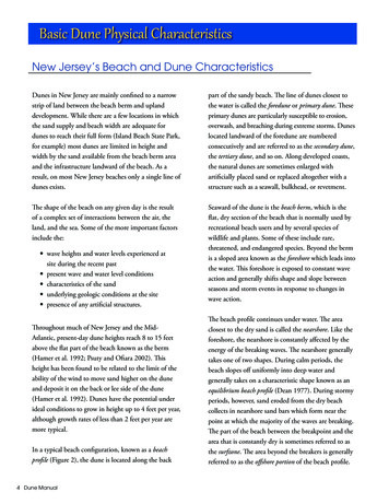
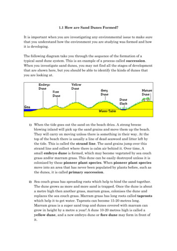
Chapter 1: Data Acquisition System1–4in SNBs are not fully understood, it is expected that a prolonged period of activity of many tensof seconds will occur over which their neutrino interactions may be observed. Individually, theseinteractions will be of low energy (relative to that of beam neutrino interactions, for example),and will be spread over time and over the bulk of the detector modules. Because of their signatureand their importance, special attention is required to first ascertain that a SNB may be occurringand to save as much data as possible over its duration.Thus the DAQ must greatly reduce the full-stream of its input data while using the data itself todo so. It must do this efficiently both in terms of recording essentially all activity important to thephysics goals of DUNE and in terms of a rate of data output that is manageable. To perform theseprimary duties the DAQ provides run control, configuration management, monitoring of both itsprocesses and the general health of the data, and a user interface for these activities.1.1.2Design ConsiderationsThe different detector modules vary in terms of their readout technology and schemes, timingsystems, channel counts and data throughput and format. These aspects determine the nature ofthe digital data input to the DAQ. The design of the DAQ strives to contain the unique layers thatadapt to the variation in the detector modules toward its front end in order to allow as many of itsback end components to remain as identical across the detector modules as possible. In particular,the DAQ must present a unified interface to the ultimate consumer of its data, DUNE offlinecomputing. It must also accept and process the data from a variety of other sources including theaccelerator, various calibration systems (including laser, cold electronics (CE), photon detectors(PDs), and potentially others) as well as trigger sources external to DUNE. The modular natureof the DUNE FD implies that the DAQ instances running on each module must also exchangetrigger information. In particular, exchanging module-local SNB trigger information will allowhigher efficiency for this important physics. The DAQ must be optimized for the above while alsoretaining the flexibility to scale to handle risks such as excess noise, changes in high voltage (HV),cut network connectivity and other issues that could arise.Currently, two major variations for the DUNE DAQ are under consideration. The eventual goalis to reduce this to a single high-level design which will service both SP and DP detector modulesand be reasonably expected to support the third and forth modules to come. The first design,designated in this proposal as nominal, is illustrated in a high-level way in terms of its data andtrigger flow in Figure 1.1. The second design, designated as the alternate, is similarly illustratedin Figure 1.2. The two variants differ largely at their FEs in terms of the order in which theybuffer the data received from the detector module electronics and use it to form trigger primitives.They also differ in how they treat triggering and data flow due to a potential SNB. As their FEsare also sensitive to differences between the detector module electronics, this further variation foreach general design is described below in Sections 1.2.2 and 1.2.3 for the detector module specificto this volume.At this general high level, the two designs are outlined. For both, the diagrams are centeredon one DAQ front-end fragment FE, which is a portion of the entire DAQ partition servicing adetector module that has one front-end computer (FEC) accepting about 10 to 20 Gbit/s of dataChapter Breakout:far-detector-single-phase.texThe DUNE Far Detector Interim Design Report
Chapter 1: Data Acquisition SystemData Flow and Trigger Primitive Productionfor one front-end DAQ fragment (out of 100)Data SourceDectector ModuleTPC and PDSElectronics( 1-10% of totalper DAQ fragment)1–5Front-end Readout(few machines per frag)Front-end Computer(one machines per frag)Data ReceiverTrigger Primitives Data ReceiverfiberTriggerPrimitivePipeline10 Gbps NICTrigger Primitives Data outfiberSNB buffering10 Gbps NICtrig rxEvent Building for one DAQ partition(nominally, one detector module)Data SinkTrigger PrimitivesSenderEvent Builder Instance(one per trigger command)Primary DAQ Buffer(RAM ringbuffer)Trigger Command (input)Fragment queryData Selector10s RAM bufSSD buf SNB data trickle10 Gbps NICOffline Disk Buffer(one storage arrayper detector module)requestrequestreceivesendDAQ Event Block10 Gbps NICTrigger Flow for one DAQ partition (nominally, one detector module)Trigger Candidate Processing FarmTrigger Primitives(collect from allDAQ fragments)TriggerCandidatePipelineTrigger Candidates(representing DAQpartition activity)Out-of-band SBN triggercommand dispatcherModule TriggerLogic UnitTrigger Command(input from just MTL)Trigger Candidates(input from ETL unit andDAQ partition TCP farm)Trigger Command(fanout to all DAQ fragmentFER machines)Trigger Commands (output)External Trigger Logic Unit(one for all FD)MTL candidates(fanin/fanout)Beam trigger (input)other external (input)Figure 1.1: The high-level, nominal design for the DUNE FD DAQ in terms of data (solid) andtrigger (dashed) flows between one DAQ front-end fragment FE and the trigger processing and eventbuilding back end for one DAQ partition. Line thickness indicates relative bandwidth requirements. Blueindicates where the full data flow for the DAQ front-end fragment is concentrated to one endpoint.Green indicates final output of normally triggered (non-SNB) data. Red indicates special handlingof potential SNB. Each detector module has specialized implementation of some of these high levelcomponents, particularly toward the upstream FE as described in the text. The grayed boxes are notin the DAQ scope.Chapter Breakout:far-detector-single-phase.texThe DUNE Far Detector Interim Design Report
Chapter 1: Data Acquisition System1–6Trigger Flow for one DAQ partition (nominally, one detector module)Trigger Candidate Processing FarmTrigger Primitives(collect from allDAQ fragments)Module TriggerLogic UnitTriggerCandidatePipelineData Flow and Trigger Primitive Productionfor one front-end DAQ fragment (out of 100)Data SourceDectector ModuleTPC and PDSElectronics( 1-10% of totalper DAQ fragment)Front-end Computer(one machines per frag)Data ReceiverfiberTrigger Primitive ProcessingAnd Primary Buffer Computers( 2/fragment)Front End BufferData Reformatterand SplitterData Dispatcher(fan out data)25-100 Gbps NICTrigger Commands (output)External Trigger Logic Unit(one for all FD)Data ReceiverMTL candidates(fanin/fanout)Primary DAQ Bufferand SNB Buffer(10s RAM ring)other external (input)SNB Buffer(SSD storage)Trigger Candidates(input from ETL unit andDAQ partition TCP farm)Trigger Candidates(representing DAQpartition activity)Beam trigger (input)Event Building for one DAQ partition(nominally, one detector module)TriggerPrimitivePipelineEvent Builder Instance(one per trigger command)Trigger PrimitivesTrigger Command (input)Data SelectorFragment queryrequestrequestsendreceiveDAQ Event BlockData Sink10 Gbps NICOffline Disk Buffer(one storage arrayper detector module)Figure 1.2: The high-level, alternate design for the DUNE FDFD DAQ in terms of data (solid) andtrigger (dashed) flows between one DAQ front-end fragment FE and the trigger processing and eventbuilding back end for one DAQ partition. Line thickness indicates relative bandwidth requirements. Blueindicates where the full data flow for the DAQ front-end fragment is concentrated to one endpoint.Green indicates final output. Note, except for a longer readout, SNB is handled symmetric to normaldata. Each detector module has specialized implementation of some of these high level components,particularly toward the upstream front-end as described in the text. The grayed boxes are not in theDAQ scope.Chapter Breakout:far-detector-single-phase.texThe DUNE Far Detector Interim Design Report
Chapter 1: Data Acquisition System1–7(uncompressed rate) from some integral number of detector units. Each of the participating DAQfront-end fragments do the following: Accept TPC and PDS data from the detector units associated with the DAQ front-endfragment. Produce and emit a stream of per-channel trigger primitives. Buffer the full data stream long enough for the trigger decision to complete (at least 10 s asdriven by SNB requirements). Accept data selection requests and return corresponding data fragments.All participating DAQ front-end fragments in the particular DAQ partition (i.e., the DAQ instance)servicing a portion of one detector module communicate with one trigger processing and eventbuilding system. The trigger processing system must: Receive the stream of per-channel trigger primitives from all DAQ front-end fragments. Correlate the primitives in time and spatially (across channels), and otherwise use them toform higher-level trigger candidates. Exchange trigger candidates with the external trigger logic (ETL). From them form trigger commands, each of which describes a portion of the data in timeand a channel to be read out, such that no two trigger commands overlap. Dispatch these commands as required (in general to the event builder (EB)).The event building system is responsible for performing the following actions: Accept a trigger command and allocate one EB instance to dispatch it. Interpret and execute the command by making data selection requests to referenced DAQfront-end fragments. Accept the returned data fragment from each DAQ front-end fragment and combine theminto a DAQ event block. Write the result to the secondary DAQ buffer, which is the boundary shared with DUNEoffline computing.The nominal and the alternate DAQ designs differ largely in where the trigger primitive and SNBbuffering exist. The nominal design places these functions in machines comprising a DAQ frontend readout (FER), which is upstream of the FEC. This then requires the SNB data and triggerhandling to be different than that for normal (non-SNB) data. When a SNB trigger command israised it is forwarded to the out-of-band trigger command dispatcher (OOB dispatcher) which sendsChapter Breakout:far-detector-single-phase.texThe DUNE Far Detector Interim Design Report
Chapter 1: Data Acquisition System1–8it down to the FERs. After the SNB data is dumped to solid-state disks (SSDs) it is “trickled”out via a path separate from the normal data to the secondary DAQ buffer. The alternate design,on the other hand, places these functions downstream of the FEC in trigger processing and databuffering nodes. The RAM of these nodes is used to provide the primary DAQ buffer for normaltriggering as well as the deeper buffers needed for SNB. This design handles the SNB data somewhatsymmetrically with normal data. When an EB makes a request for SNB data, it differs only inits duration, spanning tens of seconds of instead just a few milliseconds. The FE buffering nodes,instead of directly attempting to return the full SBN data immediately, streams it to local SSDstorage. From that storage, the data is sent to the EB as low priority (i.e., also trickled out). Sincethe module trigger logic (MTL) ensures no overlapping commands, the buffer nodes may servicesubsequent requests from post-dump data that is in the RAM buffer. Since each trigger commandis handled by an individual EB instance, the trickle proceeds asynchronously with respect to anysubsequent trigger command handled by another EB instances.Further description of these designs is given in Section 1.2.The most critical requirements for the DUNE FD DAQ are summarized in Table 1.1.Table 1.1: Important requirements on the DAQ system designRequirementDescriptionScalabilityThe DUNE FD DAQ shall be capable of receiving and bufferingthe full raw data from all four detector modulesZero deadtimeThe DUNE FD DAQ shall operate without deadtime undernormal operating conditionsTriggeringThe DUNE FD DAQ shall provide full-detector triggering functionality as well as self-triggering functionality; the data selection shall maintain high efficiency to physics events while operating within a total bandwidth of 30 PB/year for all operatingdetector modulesSynchronizationThe DUNE FD DAQ shall provide synchronization of differentdetector modules to within 1 µs, and of different subsystemswithin a module to within 10 nsThe input bandwidth and processing needs of the DAQ are expected to be dominated by the rateof data produced by the TPC system of each detector module. These rates vary between themodules and their estimations are summarized in Table 1.2.The ultimate limit on the output data rate of the DUNE FD DAQ is expected to be provided bythe available bandwidth to the tape, disk and processing capacity of Fermilab. An ample guidelinehas been established that places this limit at about 30 PB/year or 8 Gbit/s. Extrapolating to fourdetector modules, this requires a DAQ data reduction factor of almost four orders of magnitude.This is achieved through a simple self-triggered readout strategy.An overestimate of the annual triggered but uncompressed data volume for one 10 kt detectormodule is summarized in Table 1.3. It assumes a very generous and simple trigger scheme wherebythe data from the entire detector module is saved for a period longer than two drift times aroundChapter Breakout:far-detector-single-phase.texThe DUNE Far Detector Interim Design Report
Chapter 1: Data Acquisition System1–9Table 1.2: The parameters governing the pre-trigger data rate from units of each detector module TPCCEs and the aggregate throughput into the FECs of the DAQ DAQ front-end fragments. Compressionis an estimate and will be reduced if excess noise is introduced.Parametersingle-phasedual-phaseTPC unitAPACRO crateUnit multiplicity150240Channels per unit2560 (800 collection) 640 (all collection)ADC sampling2 MHz2.5 MHzADC resolution12 bit12 bitAggregate from CE1440 GB/s576 GB/sAggregate with compression 288 GB/s (5 )58 GB/s (10 )the trigger time. This essentially removes any selection bias at the cost of recording a substantialamount of data that will simply contain noise. Detailed trigger efficiency studies still remain to beperformed. Initial understanding indicates that trigger efficiency should be near 100 % for localizedenergy depositions of at least 10 MeV. Sub-MeV signals can be ascertained from noise in existingLArTPCs so the effective trigger threshold may be even lower with high efficiency. Of course, datarates rise quickly when the threshold drops into the range of an MeV. Additional simulation anduse of early data will be used to better optimize this threshold.The data volume estimates also assume that any excess noise beyond what is expected due tointrinsic electronics noise will not lead to an increase in trigger rates. If, for example, excess noiseoccurs such that it frequently mimics more than about 10 MeV of localized ionization, this wouldlead to an increase in various types of triggers and subsequently more data. However, at thesame time, these estimates do not take into account that some amount of lossless compression ofthe TPC data will be achieved. In the absence of excess noise it is expected that a compressionfactor of at least 5 can be achieved with the SP data and up to 10 may be achieved with theDP data, although the actual factor achieved will ultimately depend on the level of excess noiseexperienced in each detector module. Studies using data from the DUNE 35 ton prototype andearly MicroBooNE running have shown that a compression factor of at least 4 can be expectedeven in the case of rather high levels of excess noise.One category that will be particularly sensitive to excess noise is the trigger primitives. As discussed further in Section 1.2.3, their primary intended use is as transient objects produced andconsumed locally and directly by the DAQ in the trigger decision process. However, as theirproduction is expected to be dominated by 39 Ar decays (absent excess noise) they may carry information that proves very useful for calibration purposes. Future studies with simulation andwith early data will determine the most feasible methods to exploit this data. These may includecommitting all or a portion to permanent storage or potentially developing processes that cansummarize their data while still retaining information salient to calibration.Finally, it is important to note that early data will be used to evaluate other selection criteria.It is expected that efficient and bias-free selections can be developed and validated that save asubset of the entire detector module for any given trigger type. For example, a cosmic-muontrigger command for a SP module will indicate which anode plane assemblies contributed to itsChapter Breakout:far-detector-single-phase.texThe DUNE Far Detector Interim Design Report
Chapter 1: Data Acquisition System1–10Table 1.3: Anticipated annual, uncompressed data rates for a single SP module. The rates for normal(non-SNB triggers) assume a readout window of 5.4 ms. For planning purposes these rates are assumedto apply to a DP module as well, which has a longer readout time but fewer channels. In reality,application of lossless compression is expected to provide as much as a 5 reduction in data volumefor the SP module and as much as 10 for the DP module.Event TypeData Volume AssumptionsPB/yearBeam interactions0.03800 beam and 800 dirt muons; 10 MeVthreshold in coincidence with beam time;include cosmicsCosmics and atmospherics1010 MeV threshold, anti-coincident withbeam timeFront-end calibration0.2Four calibration runs per year, 100 measurements per pointRadioactive source calibration 0.1Source rate 10 Hz; single fragmentreadout; lossless readoutLaser calibration0.21 106 total laser pulses, lossy readoutSupernova candidates0.530 seconds full readout, average once permonthRandom triggers0.0645 per dayTrigger primitives 6All three wire planes; 12 bits per primitive word; 4 primitive quantities; 39 ArdominatedChapter Breakout:far-detector-single-phase.texThe DUNE Far Detector Interim Design Report
Chapter 1: Data Acquisition System1–11formation (i.e., which ones had local ionization activity). This command can then direct readingout these anode plane assemblies, possibly also including their neighbors, while discarding the datafrom all other anode plane assemblies. This may reduce the estimated 10 PB/year for cosmics andatmospherics by an order of magnitude. A similar advanced scheme can be applied to the DPmodule by retaining data for the given readout window from only the subset of CRO crates (andagain, potentially their nearest neighbors) that contributed to the formation of the given trigger.1.1.3ScopeThe nominal scope of the DAQ system is illustrated in Figure 1.1 by the white boxes. It includesthe continued procurement of materials for, and the fabrication, testing, delivery and installationof the following systems: FE readout (nominal design) or trigger farm (alternate design) hardware and firmware orsoftware development for trigger primitive generation. FE computing for hosting of DAQ data receiver (DDR), DAQ primary buffer (primary buffer)and data selector. Back-end computing for hosting MTL, EB and the OOB dispatcher processes. External trigger logic and its host computing. Algorithms to generate trigger commands that perform data selection. Timing distribution system. DAQ data handling software including that for receiving and building events. The online monitoring (OM) of DAQ performance and data content. Run control software, configuration database, and user interface Rack infrastructure in the central utility cavern (CUC) for readout electronics, FE computing,timing distribution, and data selection. Rack infrastructure on surface at SURF for back-end computing.Chapter Breakout:far-detector-single-phase.texThe DUNE Far Detector Interim Design Report
Chapter 1: Data Acquisition System1.21.2.11–12DAQ DesignOverviewThe design for the DAQ has been driven by finding a cost-effective solution that satisfies therequirements. Sever
Deep Underground Neutrino Experiment (DUNE) Far Detector Interim Design Report Volume2: Chapter Breakout: far-detector-single-phase.tex chapter-fdsp-daq.tex July19,2018 TheDUNECollaboration. Contents Contents i ListofFigures iii ListofTables 1 1 DataAcquisitionSystem 2