Transcription
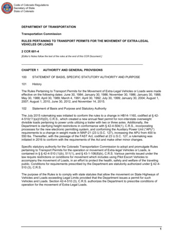
STANDARD DRAWINGSBBP-003-02ELASTOMERIC BEARING PADS FOR BOX BEAMSBDP-001-06BOX BEAM GENERAL NOTES AND REFERENCESBDP-002-03BOX BEAM BEARING DETAILSBDP-003-03BOX BEAM MISCELLANEOUS DETAILSBDP-004-04BOX BEAM TENSION ROD DETAILSBDP-009-04BOX BEAM CB27 DETAILSBGX-006-10STENCILS FOR STRUCTURESBGX-023STANDARD GRAVITY WALLBGX-024STANDARD GRAVITY WALLBHS-011BJE-001-13BPS-003-09TRANSPORTATION CABINETDEPARTMENT OF HIGHWAYSCOUNTY OFITEM NO.HICKMAN1-10063DescriptionLAYOUT SHEETR2TYPICAL SECTIONSR3ROADWAY PLAN SHEETRAILING SYSTEM SIDE MOUNTED MGSR4ENVIRONMENTALLY CLEARED AREANEOPRENE EXPANSION DAMS AND ARMORED EDGESR5ROADWAY PROFILE SHEETS1GENERAL NOTESHICKMAN COUNTYKY 80 OVER BOWLES CREEKSTA. 12 35.96TYPICAL GUARDRAIL INSTALLATIONSRBI-004-06INSTALLATION OF GUARDRAIL END TREATMENT TYPE 1RBR-001-13STEEL BEAM GUARDRAIL ("W" BEAM)RBR-005-11GUARDRAIL COMPONENTSRBR-015-06STEEL GUARDRAIL POSTSRBR-016-05TIMBER GUARDRAIL POSTSRBR-020-07GUARDRAIL END TREATMENT TYPE 1RBR-055-01DELINEATORS FOR GUARDRAILRDI-040-01EROSION CONTROL BLANKET SLOPE INSTALLATIONRDX-210-03TEMPORARY SILT FENCERDX-220-05SILT TRAP TYPE ARDX-225-01SILT TRAP TYPE BRDX-230-01SILT TRAP TYPE CRGX-001-06MISCELLANEOUS STANDARDSRGX-100-07TREATMENT OF EMBANKMENTS AT END-BENTSRGX-105-09TREATMENT OF EMBANKMENTS AT END-BENTS - DETAILSRGX-200-01ONE POINT PROCTOR FAMILY OF CURVESS2BRIDGE LAYOUTS3PILE RECORDS4END BENT 1S5END BENT 2S6RETAINING WALLS7CONSTRUCTION ELEVATIONSX1-X4CROSS SECTIONSSPECIAL NOTESFILE NAME: .\Roadw ay\Draw ing\053B00044N-R1RBI-002-07R1INDEX OF SHEETSSheet No.R1HP12x53 STEEL PILESHEET NO.TRAFFIC CONTROL ON BRIDGE REPAIR CONTRACTSCONCRETE SEALINGEND PROJECTOVER THE SIDE DRAINAGE AND MGS RAILINGSTA. 14 43.00CONTRACT COMPLETION DATE AND LIQUIDATED DAMAGESON BRIDGE REPAIR CONTRACTSBRIDGING KENTUCKY PROJECT STENCILADDITIONAL ENVIRONMENTAL COMMITMENTSTREE CLEARING RESTRICTIONSSEDIMENT PREVENTION AND EROSION CONTROLSTA. 12 35.96 CONST.1-SPAN CB27x48 BOXBEAM BRIDGESPECIAL PROVISIONS@ 0 SKEW69 EMBANKMENT AT BRIDGE END BENT STRUCTURESUSER: cquinn2:11:21PMDATE PLOTTED: 4/5/2021 1BEGIN PROJECTSTA. 11 00.00SPECIFICATIONSLOCATION MAP2019 Standard Specifications for Road and BridgeConstruction.DESIGN CRITERIA00.5 MI1 MI.2 MI.2017 AASHTO LRFD Bridge Design Specifications withCLASS OF HIGHWAY RURAL MAJOR COLLECTORFLATTYPE OF TERRAINCurrent Interims.Commonwealth of KentuckyDEPARTMENT OF HIGHWAYSDESIGN SPEEDREQUIRED NPSDREQUIRED PSDDEGREESDEGREESMINUTESMINUTES51SECONDS NORTH23 SECONDS WESTSTA25042ICE NSESGSNIONAL EDREESGSNIONAL 485LA. SHEALLATITUDEJON A.MILESOF KENTEUTFEPROGEOGRAPHIC COORDINATESKYD %T %COUNTY OFOF KENTC)DHVEUADT FUTURE ()STAT364EOFMicroStation v8.11.9.919ADT PRESENT (PRE-SHEET NAME:LEVEL OF SERVICEKY 80 OVER BOWLES CREEKITEM NO.1-10063DRAWING NO.28418PROJECTNUMBER:LETTING DATE:DESIGNED% RESTRICTED SDLEVEL OF SERVICEMAX. DISTANCE W/O PASSINGPREPARED BYEX. BRIDGE ID# 053B00044NDigitally signed by Jon MilesDN: cn Jon Miles, o QK4, ou,email jmiles@qk4.com, c USDate: 2021.04.07 13:26:23-04'00'SheaPorterDigitally signed by Shea PorterDN: cn Shea Porter,o Structures, ou Qk4,email sporter@qk4.com, c USDate: 2021.04.07 13:18:44-04'00'RECOMMENDED BY:PROJECT MANAGERDATE:PLAN APPROVED BY:STATE HIGHWAY ENGINEERDATE:
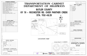
COUNTY OFITEM NO.SHEET NO.HICKMAN1-10063R2CONVENTIONAL SIGNSReplace any full depth mainline and shoulder pavementSURVEY LINEremoved as part of bridge backwall construction,400' V.C.GRADE LINEsuperstructure replacement, or other work (if includedin the Contract Documents) with a minimum of 8 inchesGROUND LINEof DGA, placed in two lifts each compacted and 8COUNTY LINEinches of CL2 ASPH BASE 1.0D PG 64-22, placed in twoCORPORATE LIMITSlifts of 4 inches each compacted. (Incidental toPLEXIST. PROPERTY LINEFoundation Prep).!EXIST. RIGHT OF WAY & PROPERTY LINE2'PROPOSED RIGHT OF WAYShldRIGHT OF WAY MONUMENTVariesVaries9'-5" to 11'-0"9'-8" to 11'-0"2'ShldNOTES:Grade point1BENCH MARKB.M. NO.4Material needed for shoulders outside ofpaved area will be measured and paid as1GRANULAR EMBANKMENTEXISTING R/W MARKEResVari0%.8Varies8.0%RIGHT OF WAY MONUMENTEXISTING/PROPOSEDESRIVATHUTILITY TEST HOLE1VARIESDetail "A"ROADWAY TYPICAL SECTIONEXISTING ROADRAILROADFENCE (CONTROLLED ACCESS)FENCE (EXCEPT STONE AND HEDGE)TREE LINEKY-80 PAVEMENTTREES1.25" CL2 Asph Surf 0.38D PG64-22PIPE CULVERT1-SFRAME1-SBRICKEND TREATMENTFILE NAME: .\Draw ing\053B00044N Typical.dgn4.00" CL2 Asph Base 1.00D PG64-224.00" CL2 Asph Base 1.00D PG64-22BRIDGEBUILDINGS4.00" CL2 Asph Base 1.00D PG64-220"-8" Base4.00" CL2 Asph Base 1.00D LGUARDRAILApply an asphalt tack1.25" CL2 Asph Surf 0.38D PG64-221.25" SurfaceEXISTINGcoat in accordance withSection 406. (IncidentalPROPOSEDof Asph Surf)LIGHTING POLEDetail "A"SHOULDERSPOWER POLEGranular EmbankmentJOINT POWER & TELEPHONE POLETELEPHONE & TELEGRAPH POLEANCHOR, POWER OR TELEPHONESTUB POWERSTUB TELEPHONEWATER MAINGAS MAINWM6"WMGM6"GMTTELEPHONE DUCTTELECTRIC DUCTEETVTV24'-0" Out to Out23'-4" Out to Out RoadwayDIRECT BURIAL TV CABLESANITARY SEWER (WITH MANHOLE)USER: cquinn:18 PMDATE PLOTTED: 3/31/20215:21STORM SEWER (WITH MANHOLE)11'-8"SANSAN11'-8"STORMSTORMDIRECT BURIAL ELECTRIC CABLEEEEDIRECT BURIAL TELEPHONE CABLETTT5" Slab Class"AA" Conc.! BridgeRail System Side2%OVERHEAD WIRE2%Mounted MGSTRAFFIC LIGHTSELECTRIC MANHOLEEMHEMHTELEPHONE MANHOLETMHTMHSTONE FENCE6 CB27 PPC Deck Units 24'-0"HEDGE FENCETAPER RATE IS 1:600 (1":50')SWAMP OR MARSH1.25" Asphalt SurfaceSPRINGSAsph. SurfaceSINKHOLEQUARRY SITEBRIDGE TYPICAL SECTION4.00" Asphalt Base3Existing Pavement4.00" Asphalt BaseMicroStation v8.11.9.919E-SHEET NAME:4.00" Asphalt Base1.25"BLUE LINE STREAM121324INTERMITTENT STREAMOR DITCH51Minimum Compacted Thickness2Asphalt Mixture For Leveling And Wedging Or Next Course Of Asphalt Mixture.3Asphalt Surface Thickness (Full Depth)4Mill Existing Pavement To Receive Asphalt Surface Full Depth (Edge Key).5Taper Length 62.5 FeetTaper LengthLAKES OR PONDSREGULATED FLOODWAYTAPERING OF OVERLAYS ON MEDIUM SPEED FACILITIES (45mph to 65mph)PREPARED BYNORTH POINTNOT TO SCALETYPICAL SECTIONKY-80OVER BOWLES CREEK
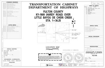
keesCrewlrBoev0o8KYBridge #053B00044NState Plane CoordinatesSTATIONDESCRIPTIONNORTH (Y) EAST (X)OFFSETELEV. (Z)5/8" REBAR & CAP3461103.453947939.63361.1009 76.7718.78' RTCP 1025/8" REBAR & CAP3461173.133948235.03360.5812 78.4514.53' LTCP 1035/8" REBAR & CAP3461150.833948484.54359.7815 23.4137.90' RTCP 1045/8" REBAR & CAP3460773.183948366.62359.5013 60.52398.44 RTOVERHEAD UTILITYELEV. 379.6614 73E 3948400.16114 00POE 14 73.16Ex R/WPROPOSED GRAVITY WALL 30'CONST. 19.75 LF11'-0"Conc. Beam onWood Posts 76'10'-4"Conc. Beam onWood Posts11'-0"9'-5"KY-80C.P.102Som e Wood Postw rapped w ith barrelfullof conc. 04'WL3TEDGE KEYWL3TCaution 24'11'-0"N 3461182.343CropFieldEx R/WE 3948451.667CropFieldN 3461178.686Bowles12 0011 0010 00E 3948059.6639'-6"CN83 1'40"E 40'11'-0" 96'9'-8"CONST. 19.2 LFEDGE KEYEx R/WTEMPORARY ELECTRIC LINEOVERHEAD UTILITYELEV. 383.43Ex R/WC.P. 103RoadRELOCATION (BY OTHERS)CropFieldRT. STA. 11 25.96 TO STA. 12 00.96 CONST.RT. STA. 12 70.96 TO STA. 13 45.96 CONST.25.0 L.F. GUARDRAIL - STEEL W BEAM-S FACEWITH 1-GUARDRAIL END TREATMENT TYPE 1CONNECT TO BRIDGE RAILING SYSTEMSIDE MOUNTED MGS.CropField25.0 L.F. GUARDRAIL - STEEL W BEAM-S FACEWITH 1-GUARDRAIL END TREATMENT TYPE 1CONNECT TO BRIDGE RAILING SYSTEMWatsonN 3461124.907STA. 14 43.00CreekN 3461137.046POB 10 00.00R3& PAVEMENTEx R/WSTA. 11 00.00E 3947960.4031-10063END PROJECT& PAVEMENT13 00FILE NAME: .\053B00044N Plan Sheet.dgnBEGIN PROJECT1:24:05 AMDATE PLOTTED: 3/31/20211HICKMANLT. STA. 12 70.96 TO STA. 13 45.96 CONST.25.0 L.F. GUARDRAIL - STEEL W BEAM-S FACEWITH 1-GUARDRAIL END TREATMENT TYPE 1CONNECT TO BRIDGE RAILING SYSTEMSIDE MOUNTED MGS.CUSER: cquinnSHEET NO.BASIS OF ELEVATIONSElevations were established by redundant GPS observations using Trimble R12 GNSS receivers on theNAVD88 vertical datum, GEOID12B utilizing Trimble RTX-PP solutions dated May 15, 2020 and wereadjusted by closed differential level loop based on the elevation of CP 104 359.50'.CP 101LT. STA. 11 25.96 TO STA. 12 00.96 CONST.25.0 L.F. GUARDRAIL - STEEL W BEAM-S FACEWITH 1-GUARDRAIL END TREATMENT TYPE 1CONNECT TO BRIDGE RAILING SYSTEMSIDE MOUNTED MGS.C.P. 101ITEM NO.PROJECT COORDINATESCoordinates for horizontal control were obtained by GPS observations using Trimble R12 GNSSreceivers on the NAD83 Kentucky State Plane Coordinate System, KY Single Zone, US Survey Feetutilizing Trimble RTX-PP solutions dated May 15, 2020. Coordinates shown are State PlaneCoordinates, US Survey Feet. No project datum factor was calculated or used for this project.COORDINATE CONTROL POINTSPOINTCOUNTY OFSIDE MOUNTED MGS.ROBERT WATSONMicroStation v8.11.9.919E-SHEET NAME:Ex R/WPREPARED BY0'20'40'80'1" 40'PLAN SHEETKY-80OVER BOWLES CREEK
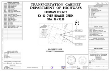
COUNTY OFITEM NO.SHEET NO.HICKMAN1-10063R4ENVIRONMENTALLY CLEARED AREA ELEVATIONLATITUDELONGITUDEELEVATIONA36 46'53.28"89 04'22.42"357E36 46'51.71"89 04'18.73"360I36 46'49.60"89 04'25.01"361M36 46'51.96"89 04'26.96"363B36 46'53.42"89 04'20.72"357F36 46'50.62"89 04'19.15"363J36 46'50.66"89 04'25.84"363N36 46'52.87"89 04'26.96"364C36 46'52.89"89 04'19.04"358G36 46'50.10"89 04'20.13"364K36 46'51.91"89 04'27.84"359O36 46'52.66"89 04'22.58"358D36 46'52.07"89 04'18.81"359H36 46'49.57"89 04'23.34"363L36 46'51.91"89 04'27.73"363NBCleared Area.dgnAOLCFILE NAME: .\053B00044N Environm entallyM14 7314 00POE 14 73.16N 3461182.343E 3948451.667CropFieldEx R/WEx R/WSom e Wood Postw rapped w ith barrelfullof conc.KY-80Conc. Beam onWood PostsC.P. 101WL3TC.P. 102WL3TCautionCN83 1'40"EEKEx R/WC.P. 103Ex R/WOVERHEAD UTILITYELEV. 383.43RoadJCropFieldCropFieldEx R/WROBERT WATSONE-SHEET NAME:MicroStation v8.11.9.919DWatson3:52 PMDATE PLOTTED: 3/31/20214:113 00OVERHEAD UTILITYELEV. 379.66CUSER: cquinnBowles12 0011 00CropFieldConc. Beam onWood PostsPOB 10 00.00N 3461124.907E 3947960.40310 00CreekEx R/WFIGHPREPARED BY0'20'40'80'ENVIRONMENTALLY CLEARED AREAKY-80OVER BOWLES CREEK
DATUMSCALE: 1" 40' HORIZONTAL1" 4' VERTICALCOUNTY OFITEM NO.SHEET NO.HICKMAN1-10063R5DATUMBEGIN PROJECTFILE NAME: C:\PW WORKING\D0263079\053B00044N PROFILE SHEET.DGNAND PAVEMENTVPI 14 43.03ELEV 361.72'VPI 12 82.54ELEV 362.40'BRIDGE @ 0 SKEW366ELEV 362.40'VPI 11 00.00ELEV 361.99'368STA. 12 35.96 CONST.1-SPAN (70')CB27x48CONCRETE BOX BEAM370VPI 11 95.37370368366END PROJECTAND PAVEMENTSTA. 11 00.00364STA. 14 43.03364PROPOSEDGRADEExisting Ground0.00%%340.3620.42%362360360Bridge Removal Note:The existing 2-Span 68' x 24' PPC Box Beam bridge shall be removed358in accordance with the current Specifications. All material in theLOW BEAMELEV. 359.36Existing Hydraulic Opening 647.73 S.F.358existing bridge shall remain the property of the Contractor andshall be disposed of in accordance with the current Specifications.Proposed Hydraulic Opening 649.05 S.F.Lump Sum payment in full shall include the complete removal of thebridge, piers to the streambed elevation, existing man-made debris,356356abutments and appurtenances.354354352352Note:by the contractor at the end of the project and the creek shall be restored350to its preconstruction condition.35034634434434234234034010 0010 4010 6010 8011 0011 2011 4011 6011 8012 0012 2012 4012 6012 8013 0013 2013 4013 6013 8014 62.0362.010 2014 2014 40361.7346361.7348361.73348362.1MicroStation v8.11.9.919E-SHEET NAME:USER: cquinnDATE PLOTTED: March 31, 2021All material that was placed or that has fallen into the creek shall be removed14 60PREPARED BYPROFILE SHEETKY-80OVER BOWLES CREEK
General NotesSpecifications: References to the specifications are to the current edition of theUtilities: The contractor shall be responsible for locating any and all existing utilitiesKentucky Department of Highways Standard Specifications for Road and Bridgeprior to excavation of material or installation of guardrail or other constructionConstruction including any current supplemental specifications. All references toactivities that may involve utilities (overhead or underground).the AASHTO specifications are to the AASHTO LRFD Bridge Design Specifications,Piling: Piling shall be driven to practical refusal as defined on the pile record sheet.Test piles shall be driven where designated on the plans to determine the length of pilerequired.Verifying Field Conditions: The contractor shall field verify all dimensions before ordering8th edition with interims.Design Load: This bridge is designed for KYHL-93 live load, (i.e. 1.25xAASHTO HL93 live load).material. New material that is unsuitable because of variations in the existing structureAll test piles shall be accurately located so that they may be used in the finishedshall be replaced at the contractor's expense.structure.This bridge is designed for a future wearing surface of 15 psf.Dimensions: Dimensions are for a normal temperature of 60 degrees fahrenheit. LayoutDesign Method: All reinforced concrete members are designed to be equivalent or greaterdimensions are horizontal dimensions.Contrary to the standard drawings for steel piling, mill test reports are not required to benotarized.than the load and resistance factor design method as specified in the current AASHTOSuperstructure Slab: The superstructure slab shall be poured continuously from end toSpecifications.end of slab before the concrete is allowed to set.Materials Design Specifications:Mastic Tape: Mastic Tape used to seal joints is to meet the requirements of ASTM C-877For Class "A" Reinforced Concretef'c 3500 psiFor Class "AA" Reinforced Concretef'c 4000 psiType I, II, or III. The joint is to be covered with 12" wide mastic tape. Prior to application,For Steel Reinforcementfy 60000 psithe joint surface shall be clean and free of dirt, debris, or deleterious material. Primer, ifrequired by the tape manufacturer, shall be applied for a minimum width of 9" on each sideMaterial Specifications: AASHTO Specifications or ASTM, current edition, as designatedof the joint.below shall govern the materials furnished.Mastic Tape shall be either:AASHTO M153Premolded Cork Filler, Type IIAASHTO M-31Deformed and Plain Billet-Steel for Concrete Reinforcement,EZ-Wrap Rubber by Press-seal Casket Corporation,Grade 60Seal Wrap by Mar Mac Manufacturing Co. Inc.,Cadilloc by The UP Rubber Co. Inc.or approved equal.Preformed Cork Expansion Joint Material: Preformed Cork Expansion Joint Material shallconform to subsection 807.04.02 (Type II) of the Kentucky Department of Highways StandardMastic Tape shall cover the joint continuously unless otherwise shown in the plans.Mastic Tape shall be spliced by taping a minimum of 6" and in accordance with theSpecifications.manufacturer's recommendations with the overlap running downhill.FILE NAME: .\Working\S1GeneralNotes.dgnConcrete: Class "AA" Concrete is to be used throughout the superstructure and in theportions of the substructure above the tops of caps. Class "A" concrete is to be used inThe cost of labor, materials, and incidental items for furnishing and installing Mastic Tapethe substructure below the caps. Prestressed beam concrete shall be in accordance withshall be considered incidental to the unit price bid for concrete class 'AA' and no separatethe plans and specifications.measurement of payment shall be made.Reinforcement: Dimensions shown from the face of concrete to bars are to center of barsTemporary Supports: Temporary Supports or shoring will not be permitted under the beamsunless otherwise shown. Spacing of bars is from center to center of bars. Any reinforcingwhen pouring the concrete deck slab or when taking "top of beam" elevations.bars designated by suffix "e" in the plans shall be epoxy coated in accordance with section811.10 of the Standard Specifications. Any reinforcing bars designated by suffix "s" in aArmored Edge: Fabricate armored edge to match cross slope and parabolic crown at eachBill of Reinforcement shall be considered a stirrup for purposes of bend diameters.end of bridge.CONSTRUCTION IDENTIFICATION: The following stencils shall be imprinted in new concreteElastomeric Bearing Pads: Elastomeric Bearing Pads shall conform to the AASHTO(or painted on steel) in accordance with the guidance outlined in the Special Note forStandard Specifications for Highway Bridges, Division II, Section 18.Bridging Kentucky Project Stencil:Bearings shall be Low Temperature Grade 3 with a shear modulus between 95 psi and 130 psi- Bridging Kentucky Logo- Year and Design Loadingand shall be subjected to the load testing requirements corresponding to Design- Drawing Number- ContractorMethod B. The cost of bearing pads is to be included in the unit price per linear feetfor Precast Beams.The Contractor shall furnish all plans, equipment, and labor necessary to do the work forwhich no direct payment will be made.Foundation Preparation: Foundation Preparation shall be in accordance with Section 603of the Specifications.Beveled Edges: All exposed edges shall be beveled ƒ", unless otherwise shown.USER: cquinn1:33:25 AMDATE PLOTTED: 4/5/2021 1Foundation excavations should be properly braced/shored to provide adequate safety toPayment for Precast Concrete Beams: The basis of payment for the Prestressed ConcreteBeams shall be at the contract unit price per linear foot of beam, in accordance withpersons working in or around excavations. Bracing should be performed in accordancewith applicable federal, state and local guidelines.the specifications.Temporary shoring, sheeting,cofferdams, and/or dewatering methods may be required toSlope Protection: Slope Protection at abutments shall be dry cyclopean stone riprap inaccordance with the plans and specifications.Geotextile Fabric, Class 1 shall be placedfacilitate foundation construction. It should be anticipated that groundwater will beencountered at foundation locations within the flood plain.between the embankment and the slope protection in accordance with StandardSpecifications 214 and 843.Payment for Geotextile Fabric, Class 1, shall be consideredincidental to the unit price bid for Dry Cyclopean Stone Riprap.Temporary shoring, bracing, sheeting, cofferdams and dewatering shall be included in theLump Sum Bid for Foundation Preparation.Completion of the Structure: The contractor is required to complete the structure inaccordance with the plans and specifications. Material, labor, or constructionStructural Granular Backfill: Materials for Structural Granular Backfill shall be in accordancewith Section 805 of the Specifications.operations not otherwise specified, are to be included in the bid item most appropriate tothe work involved. This may include cofferdams, shoring, excavations, backfilling,removal of all or parts of existing structures, phase construction, incidental materials,Contrary to the Specifications, Structural Granular Backfill will not be measured for paymentbut shall be included in the Lump Sum Bid for Foundation Preparation.labor, or anything else required to complete the structure.REVISIONOpenRoads Designer v10.13.7.1 E-SHEET NAME:Concrete Sealer:Shop Drawings: The fabricator shall submit all required shop plans, by email to SHOP053B00044N@docs.e-Builder.net, for review.Apply concrete sealer in accordance with the Special Note Concrete Sealing.These submissions shall depict the shop plans in.PDF format, as either 11"x17" or 22"x36" sheets.Designers will make review comments on theseelectronic submissions as needed and, if required, shall return them to the fabricator forCHECKED BYDESIGNED BY:S. PORTERJ. WOOTENDETAILED BY:J. WOOTENS. PORTERCommonwealth of KentuckyDEPARTMENT OF HIGHWAYScorrections and resubmittal. Upon acceptable reconciliation of all comments, files shall besent to the Bridging Kentucky Shop Plan Coordinator for distribution.DATEMARCH 2021DATE:Only plans submittedCOUNTYdirectly to the Shop Plan Coordinator will be distributed. Additionally, only plans electronicallyHICKMANstamped "Distributed by The Bridging Kentucky Program Team" are to be used for fabrication.While this process does not require the submission of paper copies, the Engineer of RecordROUTEreserves the right to require such copies on a case by case basis.CROSSINGKY 80BOWLES CREEKWhen any changes to the design plans are proposed, the shop drawings reflecting theseGENERAL NOTESchanges shall be submitted through the process above.ITEM NUMBER1-10063.00PREPARED BYSHEET NO.S1DRAWING NO.28418
3640.43%Elev. 362.40'PVI 12 82.54Elev. 362.40'PVI 11 95.37KY 123WATSON RD.0.00%-0.42%3623601Geotextile Fabric andLimits of StructuralElev. 359.25Granular Backfill (Typ.)Pile CutoffElev. 358.25Preparation. Structure348Granular Backfill is estimatedBottom Cap2'-0'' ThickElev. 352.10Cyclopean Stone346at 300 cubic yards.(Information Only)set, and tensioning rods aretightened.Armored EdgeEnd of BridgeBottom CapElev. 351.17ElastomericBearing PadMastic TapeClass 1 (Typ.)342beams are set, dowel bars are5'-0"(Typ.)Geotextile FabricHP 12x53 (Typ.)to BeamElev. 358.25Rip Rap over344Do not place backfill untilMeasured ParallelPile Cutoff350incidental to Foundation9'' 9"Berm Width VariesElev. 359.25352Structure Granular Backfill isBerm Width VariesLow Beam Seat353.17p354Low Beam SeatBerm Elev.oSpecial Provision 69.354.10350method of construction, see356LoFor end bent backfill andBerm Elev.1358350Note:2'-0'' #8 Epoxy CoatedDowel Bar340ELEVATION33868'-6" Single Span CB27 PPC Box BeamEND BENT #1336Back Faceof E.B.END BENT #2Live Load 1.25 x HL-93 (KY HL-93)(FIX)(FIX)24'-0" Roadway Width 0 Skew.! BearingDatum Line33413 0035012 00END OF BEAM DETAIL70'-0" Out to Out35068'-6" ! Brg. to ! Brg.3509"15' Long StandardNote:Contractor shall provide 12" widemastic tape to water-proof the jointbetween slab ends and abutment. Tape9"shall be looped as shown at expansion endsof bridge to prevent damage to tape.360Gravity Retaining Wall603360360360FILE NAME: DGNSPEC 350360! Brg. E.B #1Sta. 12 01.70! BridgeKY-80Begin BridgeSta. 12 70.95Limits of! Brg. E.B #2CyclopeanSta. 12 70.20053Sta. 12 00.95End BridgeBowles C36005336060360336010'-0" (Typ.).0033'Profile Grade ".0133' ".0300'⅜" ".0033'Concrete Surface.0133'! Bridge "USER: USER 36010'-0" (Typ.)DATE PLOTTED: DATE TIME reekStone Rip-RapPLAN0%2.{-(Superstructure Not o beam camber being different from the designer's assumptions, is the contractor'sresponsibility and at no cost to the department.S2 Bar@ 12"Max.Spacing1concrete was calculated. Any additional concrete required above the plan quantity, due2%Mounted MGSTypeNo. Size LengthftinLocationS1eStr.485361Slab LongitudinalS2eStr.705238Slab TransverseCHECKED BYDESIGNED BY:S. PORTERJ. WOOTENDETAILED BY:J. WOOTENS. PORTERCommonwealth of KentuckyDEPARTMENT OF HIGHWAYSCOUNTY2'-0"TOE OF SLOPE DETAILHICKMANROUTECROSSINGBOWLES CREEKKY-80LAYOUTBILL OF REINFORCEMENTMarkDATEMARCH 2021DATE:Rail System Side6'-0" Parabolic Crown2%esriVa2'-0"(2 Lengths Ea. Min. Lap 2'-5")Clr.Contrary to the Standard Drawings (5" thickness), the construction elevationswill cause the slab to be approximately 6 1/2" thick at each end and go toSlabClass"AA" Conc.24 S1 Bars @ 12" 23'-0"3505"E-SHEET NAME:3501 Note:Line23'-4" Clear Roadway WidthPARABOLIC CROWNapproximately 5 1/2" thick at the center of span. This is how the quantity of class "AA"MicroStation v8.11.9.919Ground"-02'24'-0" Out to Out6'-0" Vertical CurveITEM NUMBER6 CB27x48 @ 4'-0" 24'-0"TYPICAL SECTIONNote:All Slab Reinf.to be Epoxy Coated1-10063.00PREPARED BYSHEET NO.S2DRAWING NO.28418
PILE RECORD FOR FRICTION PILES USING FHWA MODIFIED GATES METHODPile ProjectNo. HammerNumberPileCut-offElevationPileLengthIn PlaceEstimatedPile TipElevationFEETFEETFEETHighest AllowablePile TipPile TipElevationElevationAs DrivenFEETFEETDesign FactoredAxial LoadKIPSTONSActual at EOD (Last 10 Blows)Required Nominal Hammer FuelAxial ResistanceSetting atEODKIPSTONSSetINCHBlow CountHammerActual(N)Stroke (H)No. ofBlows BLOWS PER INCH FEETDeveloped HammerEnergy (E)*Calculated NominalAxial Resistance (Rn)FT-LBSTONSPile ProjectNo. HammerNumberPileCut-offElevationPileLengthIn PlaceEstimatedPile TipElevationFEETFEETFEETHighest AllowablePile TipPile TipElevationElevationAs DrivenFEETDesign FactoredAxial SINCHDeveloped HammerEnergy (E)*Calculated NominalAxial Resistance 5306.25325.0011859295147.5738495KIPSActual at EOD (Last 10 Blows)Blow CountHammerActual(N)Stroke (H)No. ofBlows BLOWS PER INCH FEETSetEND BENT #2END BENT #11Required Nominal Hammer FuelAxial ResistanceSetting atEOD358.25304.25325.0013668340170101168'-6"Test Pile#6#1Notes#7#2#4encountering excessive blow counts or damaging the#8piles.3'-6"90 0'0p".The Contractor shall submit the proposed piledriving system to the Engineer for approval prior tothe installation of the first pile.Approval of the piledriving system by the Engineer will be subject to3'-6"! Bridgeto drive 12x53 steel H-piles to practical refusal withoutTy6 HP12x53 @ 7'-0" 35'-0"FILE NAME: .\Working\S3-Pile5½#3A diesel pile driving hammer with a rated energybetween 40 foot-kips and 165 foot-kips will be requiredBowles Creek"Record.dgnSta. 12 01.705 HP12x53 @ 8'-0" 32'-0"! Brg. E.B #11.satisfactory field performance of the pile drivingprocedures.2.#9If hard driving is encountered because of densestrata or an obstruction, such as a boulder before! Brg. E.B #2the pile is advanced to the depth anticipated, theSta. 12 70.20Engineer will determine if more blows than the averagedriving resistance specified for practical refusal isrequired to further advance the pile.Drive additionalproduction and test piles if directed by the Engineer.#103.The installation of the pile foundations shouldconform to current AASHTO LRFD Bridge DesignSpecifications, and Section 604 of the current editionof the Kentucky Department of Highways Standard#5PLANSpecifications for Road and Bridge Construction.#11OpenRoads Designer v10.13.7.1 E-SHEET NAME:USER: cquinn1:40:24 AMDATE PLOTTED: 4/5/2021 1Test PileDefinitions of TermsPILE CUT-OFF ELEVATION: Elevation of the top of pile in the finished structure.PILE LENGTH IN PLACE: Actual pile length below the Pile Cut-Off Elevation in the finishedstructure.PILE TIP ELEVATION AS DRIVEN: Actual Pile Tip elevation in the finished structure.Driving CriteriaDESIGN FACTORED AXIAL LOAD: The design factored strength loads as estimated fromstructural design calculations.REQUIRED NOMINAL AXIAL RESISTANCE: The total geotechnical axial resistance required bythe pile to satisfy applicable design requirements. This is arrived at by dividingthe Design Factored Axial Load by the resistance factor, ɸ 0.40, plus any otherapplicable considerations such as scour, embankment layers, etc. Note that dynamicformulas, including the FHWA Modified Gates Formula, should not be used when therequired nominal axial resistance exceeds 600 kips.END OF DRIVING (EOD): When the pile was driven to tip elevation.Satisfy two criteria when driving friction piles:1. Drive piles to the Highest Allowable Pile Tip Elevation2. Drive piles until the Calculated Nominal Pile Resistance (Rn) is equal to theRequired Nominal Pile Resistance at End of Driving (EOD).Hammer fuel setting shall be adjusted so that the blow count at the end of drivingranges from 3 to 10 blows per inch.REVISIONField DataFor each pile, the Project Engineer shall record the following on this sheet: PileLength in Place and Point of Pile Elevation as Driven.DATEMARCH 2021DATE:CHECKED BYDESIGNED BY:S. PORTERJ. WOOTENDETAILED BY:J. WOOTENS. PORTERSubmit this record to:HAMMER STROKE (H): The length of the free-fall of the ram for a gravity, diesel orsingle-acting steam or compressed air hammer.DEVELOPED HAMMER ENERGY (E): This is the energy of the ram impact for a given blow.If a direct energy reading is not taken, "E" can be assumed to be the ram weight(in pounds) times the hammer stroke (in feet). (E WH) ft-lbs.SET: Amount of downward veritical displacement in the pile over the last 10 blows.BLOW COUNT (N): Number of hammer blows per inch at the end of initial driving to betaken as 10 blows divided by the Set in inches.FHWA MODIFIED GATES FORMULA: Calculated Nominal Pile Resistance Rn 0.875 E log10 (10N) - 50Resulting value is in tons. The Modified Gates Formula is only applicable at the End ofDrive (EOD) and may not be applied at Beginning of Restrike (BOR).If the Calculated Nominal Pile Resistance (Rn) is achieved at an elevation higher thanthe Highest Allowable Pile Tip Elevation, continue driving until the Highest Allowable PileTip Elevation is reached. If the pile cannot be advanced to the Minimum Point of PileElevation or if the pile is being driven "significantly" past the Estimated Pile TipElevation, consult the Central Office Division of Construction.Commonwealth of KentuckyDEPARTMENT OF HIGHWAYSKentucky Transportation CabinetDirector, Division of Structural Design3rd Floor EastCOUNTY200 Mero StreetHICKMANFrankfort, KY 40622ProjectHammerWeight of RamMaximumHammerManufacturerWRated EnergyNumberand ModelLbs.Ft-LbsROUTEThis pile record does not replace other pile records the Project Engineer isrequired to keep and submit.Use HP 12x53 in accordance with BPS-003, c.e.ITEM NUMBER1-10063.00CROSSINGKY 80BOWLES CREEKPILE RECORDPREPARED BYSHEET NO.S3DRAWING NO.28418
32 18 11 6582Ft.In.583LengthABFt.In.Ft.In.Ft.In.11 n.Ft.In.Ft.In.111 thFt.In.31 9LengthFt.In.11 48 6236s5#5#5#5LengthABFt.In.Ft.In.Ft.In.8 58 78262LengthABCDFt.In.Ft.In.Ft.In.Ft.In.Ft.In.8 108 46280605 16LengthAABDBFt.I
box beam cb27 details bps-003-09 hp12x53 steel pile bdp-001-06 bdp-004-04 ky 80 over bowles creek over the side drainage and mgs railing bridging kentucky project stencil additional environmental commitments @ 0 skew beam bridge 1-span cb27x48 box sta. 12 35.96 const. sta. 11 00.00 begin project sta. 14 43.00 end project 0.5 mi 1 mi. 2 mi.