Transcription
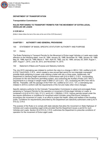
STANDARD DRAWINGSBBP-003-02ELASTOMERIC BEARING PADS FOR BOX BEAMSBDP-001-05BOX BEAM GENERAL NOTES & REFERENCESBDP-002-03BOX BEAM BEARING DETAILSBDP-003-03BOX BEAM MISCELLANEOUS DETAILSBDP-004-03BOX BEAM TENSION ROD DETAILSBDP-005-05RAILING SYSTEM TYPE IIBDP-010-04BOX BEAM B33 AND CB33 DETAILSBGX-006-10STENCILS FOR STRUCTURESBJE-001-13NEOPRENE EXPANSION DAM AND ARMORED EDGESBPS-003-09TRANSPORTATION CABINETDEPARTMENT OF HIGHWAYSTYPICAL SHEETR3PLAN SHEETHP12X53 STEEL PILER4PROFILE SHEETRBI-002-07TYPICAL GUARDRAIL INSTALLATIONSS1GENERAL NOTESRBR-005-11GUARDRAIL COMPONENTSS2LAYOUT SHEETS3PILE RECORDS4ABUTMENTSRDX-220-05SILT TRAP ARDX-225-01SILT TRAP BRGX-001-06MISCELLANEOUS STANDARDSRGX-200-01ONE POINT PROCTOR FAMILY OF CURVES3-10003R1DescriptionR2TEMPORARY SILT FENCEBUTLERSHEET NO.INDEX OF SHEETSTITLE SHEETRDX-210-03ITEM NO.Sheet No.R1RDI-040-014 EROSION CONTROL BLANKET SLOPE INSTALLATIONCOUNTY OFBUTLER COUNTYKY 70 - ROCHESTER RD. OVER PANTHER CREEKSTA. 1132 62.25BEGIN PROJECTSTA. 1131 70.00ACTIVE SEPIASSPECIAL NOTESSEPIA 009TREATMENT OF EMBANKMENTS AT END-BENTSSEPIA 010TREATMENT OF EMBANKMENTS AT END-BENTS - DETAILSCONTRACT COMPLETION DATE AND LIQUIDATED DAMAGESSEPIA 024TYPICAL GUARDRAIL INSTALLATIONTRAFFIC CONTROL ON BRIDGE REPAIR CONTRACTSSEPIA 027STEEL BEAM GUARDRAIL ("W" BEAM)SEPIA 028STEEL GUARDRAIL POSTSSEPIA 032DELINEATORS FOR GUARDRAILBRIDGE OVERLAY APPROACH PAVEMENTPORTABLE CHANGEABLE MESSAGE SIGNSSTA. 1132 62.25EROSION PREVENTION AND SEDIMENT CONTROL1-SPAN (82.5') CB33x48SEPIA 033GUARDRAIL SYSTEM TRANSITIONSEPIA 035RAILING SYSTEM TYPE II GUARDRAIL TREATMENTBRIDGE REMOVALCONCRETE BOX BEAMCONCRETE COATINGFILE NAME: DGNSPEC BRIDGE @ 0 SKEWSPECIAL PROVISIONS69 EMBANKMENT AT BRIDGE END BENT STRUCTURESEND PROJECTUSER: USER DATE PLOTTED: DATE TIME STA. 1133 54.00SPECIFICATIONSLOCATION MAP2012 Standard Specifications for Road and BridgeConstruction.DESIGN CRITERIA2017 AASHTO LRFD Bridge Design Specifications withCLASS OF HIGHWAY RURAL SECONDARYCurrent Interims.N9100B061D # 0eIgdigBrnitsixETYPE OF TERRAINCommonwealth of KentuckyDEPARTMENT OF HIGHWAYSDESIGN SPEEDREQUIRED NPSDREQUIRED PSDD %CHRISTOPHER D.GEOGRAPHIC MINUTESMINUTES3527991LICDSEENSGSNIONAL ESECONDS NORTH51 SECONDS WESTSFEPROPADGETTT %ETCOUNTY OFOF KENTUBUTLERCLAYTEN N.GINE ER)DHVETINEERSTA1,569YCKADT FUTURE ()YCKE-SHEET NAME:2016FEPROMicroStation v8.11.9.459ADT PRESENT (STAOF KENTULEVEL OF SERVICEGREENWELL33398LDICENSESINONAL EITEM NO.3-10003DRAWING NO.27854PROJECTNUMBER:LETTING DATE:FEBRUARY 22, 2019DESIGNED% RESTRICTED SDLEVEL OF SERVICEMAX. DISTANCE W/O PASSINGPREPARED BYChrisPadgettDigitally signed by Chris PadgettDN: cn Chris Padgett, o Qk4,ou Transportation,email cpadgett@qk4.com, c USDate: 2019.01.08 14:08:46 -05'00'Clayten N.GreenwellDigitally signed byClayten N. GreenwellDate: 2019.01.0813:40:00 -05'00'RECOMMENDED BY:PROJECT MANAGERDATE:PLAN APPROVED BY:STATE HIGHWAY ENGINEERDATE:
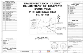
COUNTY OFITEM NO.SHEET NO.BUTLER3-10003R2CONVENTIONAL SIGNSSURVEY LINE400' V.C.GRADE LINEGROUND LINENOTES:COUNTY LINECORPORATE LIMITS1 DGA Base needed for shoulders outside ofPLEXIST. PROPERTY LINEpaved area will be measured and paid asEXIST. RIGHT OF WAY & PROPERTY LINEGRANULAR EMBANKMENT in accordance with thePROPOSED RIGHT OF WAYSpecial Note for Bridge Overlay Approach Pavement!2'-0"RIGHT OF WAY MONUMENT2222'-0"Varies 0' to 2'-0"10'-5" to 13'-3"11'-1" to 13'-3"ShldBENCH MARKVariesVariesShldGrade pointB.M. NO.4EXISTING R/W MARKER1VariesesVari0%.88.0%RIGHT OF WAY MONUMENTEXISTING/PROPOSEDTHVARIESESRIVAUTILITY TEST HOLE1Detail "A"EXISTING ROADROADWAY TYPICAL SECTIONRAILROADFENCE (CONTROLLED ACCESS)FENCE (EXCEPT STONE AND HEDGE)TREE LINETREESKY 70 PAVEMENTPIPE CULVERTCULVERT8.00" DGA Base16.00" BaseBRIDGEBUILDINGS1-SFRAME1-SBRICKEND TREATMENTSHED4.00" CL2 Asph Base 1.00D PG64-224.00" CL2 Asph Base 1.00D 25" SurfaceEXISTING1.25" CL2 Asph Surf 0.38D PG64-22PROPOSEDSHOULDERSLIGHTING POLE1.25" CL2 Asph Surf 0.38D PG64-22POWER POLEGranular Embankment14.00" CL2 Asph Base 1.00D PG64-22JOINT POWER & TELEPHONE POLE4.00" CL2 Asph Base 1.00D PG64-22TELEPHONE & TELEGRAPH POLE8.00" DGA BaseFILE NAME: DGNSPEC ANCHOR, POWER OR TELEPHONESTUB POWERSTUB TELEPHONEWATER MAINGAS MAINTELEPHONE DUCTELECTRIC DUCTDIRECT BURIAL TV CABLESANITARY SEWER (WITH MANHOLE) TIME STORM SEWER (WITH MANHOLE)WM6"WMGM6"GMDetail "A"TTEETVTVSANSANSTORMSTORM28'-0''DIRECT BURIAL ELECTRIC CABLEEEEDIRECT BURIAL TELEPHONE CABLETTT9"OVERHEAD WIRE13'-3"13'-3"9"USER: USER DATE PLOTTED: DATE TRAFFIC LIGHTS5" SlabELECTRIC MANHOLEEMHEMHTELEPHONE MANHOLETMHTMH! BRIDGECL "AA" Conc.2.0%Profile GradeRailing System Type II2.0%STONE FENCEHEDGE FENCESWAMP OR MARSHSPRINGSSINKHOLE7-CB33 Box BeamsMicroStation v8.11.9.459E-SHEET NAME:QUARRY SITEBLUE LINE STREAMBRIDGE TYPICAL SECTIONBEFORE YOU DIGINTERMITTENT STREAMOR DITCHLAKES OR PONDSThe contractor is instructed to call 1-800-752-6007 to reach KY 811, the one-call systemfor information on the location of existing underground utilities. The call is to be placeda minimum of two (2) and no more than ten (10) business days prior to excavation. Thecontractor should be aware that owners of underground facilities are not required to bemembers of the KY 811 one-call Before-U-Dig (BUD) service. The contractor must coordinateexcavation with the utility owners, including those whom do not subscribe to KY 811. Itmay be necessary for the contractor to contact the County Court Clerk to determine whatutility companies have facilities in the area.REGULATED FLOODWAYPREPARED BYNORTH POINTNOT TO SCALETYPICAL SECTIONS & LEGENDKY 70 - ROCHESTER RD.OVER PANTHER CREEK
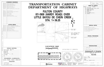
COUNTY OFITEM NO.SHEET NO.BUTLER3-10003R3R RD.TES0-ROCHEKY 7N9100B061D # 0eIgdigBrnitsixEPROJECT COORDINATESCoordinates for horizontal control were obtained by redundant GPS observations using Trimble R10GNSS receivers. On the NAD83 Kentucky State Plane Coordinate System, KY Single Zone, US SurveyFeet utilizing the KYCORS RTN GPS Network on October 24, 2018. Coordinates shown are State PlaneCoordinates, US Survey Feet. No project datum factor was calculated or used for this project.thLT. STA. 1133 00 TO STA. 1133 54REMOVE 54 L.F. GUARDRAILBASIS OF ELEVATIONSElevations were established by redundant S7 Robot and GPS observations NAVD88 vertical datum, Geoid12B utilizing the KYCORS RTN Network.LT. STA. 1133 04.00 TO STA. 1133 54.00 CONST.RT. STA. 1131 70 TO STA. 1132 24REMOVE 54 L.F. GUARDRAILLT. STA. 1131 70.00 TO STA. 1132 20.00 CONST.25 L.F. GUARDRAIL-STEEL W BEAM-S FACE A25 L.F. GUARDRAIL-STEEL W BEAM-S FACE AWITH 25 L.F. GUARDRAIL-STEEL W BEAM-S FACEWITH 25 L.F. GUARDRAIL-STEEL W BEAM-S FACECONNECT TO BRIDGE RAIL SYSTEM TYPE IICONNECT TO BRIDGE RAIL SYSTEM TYPE IIAND TIE TO EXISTING GUARDRAILDELISA J MCGUYER35 001134 0011DELISA J MCGUYER33 001132 0011 00311130 0011AND TIE TO EXISTING GUARDRAILBEGIN PROJECTKREER CTHEPANSTA. 1131 70.00N 3589684.19E 4601408.49EX. R/W6"EX. R/WAPPROXIMATE LOCATION6"STA. 1133 45.00PIEND APPROACH PAVEMENTGNSIGNSI11'-1"FILE NAME: DGNSPEC R RD.STEE0 - ROCHY 7K10'-5"10'-9"PI#3CPGNSIGNSIPIEX. R/WEND PROJECTRT. STA. 1131 70.00 TO STA. 1132 20.00 CONST.25 L.F. GUARDRAIL-STEEL W BEAM-S FACE ASTA. 1133 54.00WITH 25 L.F. GUARDRAIL-STEEL W BEAM-S FACECONNECT TO BRIDGE RAIL SYSTEM TYPE IISTA. 1132 63 REMOVE EXIST.N 3589638.43AND TIE TO EXISTING GUARDRAIL3-SPAN STEEL I-BEAM BRIDGE,E 4601586.71ABUTMENTS AND PIERSRT. STA. 1131 70 TO STA. 1132 24REMOVE 54 L.F. GUARDRAILRT. STA. 1133 04.00 TO STA. 1133 54.00 CONST.25 L.F. GUARDRAIL-STEEL W BEAM-S FACE AWITH 25 L.F. GUARDRAIL-STEEL W BEAM-S FACECONNECT TO BRIDGE RAIL SYSTEM TYPE IIRT. STA. 1131 80.00 TO STA. 1132 35.00AND TIE TO EXISTING GUARDRAILREMOVE AND RESET 55' OF EXISTING FENCE IFNEEDED TO MOVE OUTSIDE OF TOE OF SLOPEDELISA J MCGUYERRT. STA. 1133 00 TO STA. 1133 54REMOVE 54 L.F. GUARDRAILMicroStation v8.11.9.459E-SHEET NAME:WETLANDS1COORDINATE CONTROL POINTSPOINTDESCRIPTIONNORTH (Y)EAST (X)ELEV. (Z)1DELISA J MCGUYERState Plane CoordinatesSTATIONOFFSETCP #1C.P. MON. W/ALUM. CAP3589824.3574600899.287430.178--CP #2C.P. MON. W/ALUM. CAP3589547.8594601988.228429.895--CP #35/8" REBAR & CAP3589663.3114601429.870431.3201131 95.9014.90' RT.CONTRACTOR IS TO AVOID AND NOT TO DISTURB THEDEPICTED ENVIRONMENTAL SENSITIVE AREA AS SHOWNON THE PLANS0'20'40'80'PREPARED BYSCALE: 1" 20'PLANKY 70 - ROCHESTER RD.OVER PANTHER CREEK776.550E 4601EX. R/W35 50.001POE 1N 3589589.695BEGIN APPROACH PAVEMENT95.3971E 460129 50.001POB 1N 3589738.894 TIME STA. 1131 80.00DATE PLOTTED: DATE USER: USER R RD.STEE0 - ROCHY 7K11'-1"
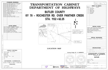
DATUMCOUNTY OFITEM NO.SHEET NO.BUTLER3-10003R4SCALE: 1" 20' HORIZONTAL1" 2' VERTICAL446DATUM444442442440440STA. 1132 62.25 CONST.1-SPAN (82.5')CB33x48CONCRETE BOX BEAMBRIDGE @ 0 SKEW444436FILE NAME: C:\PW WORKING\D0147760\016B00019N PROFILE.DGN434END APPROACHCONSTRUCTIONSTA. 1133 45.00PROPOSEDGRADE4364340.22%0%40.432438PVI 1133 45.00Elev 432.30PVI 1131 80.00Elev 431.87BEGIN APPROACHCONSTRUCTIONSTA. 1131 80.00PVI 1132 15.03Elev 432.01438432430430428428PROPOSEDLOW BEAMEL. 428.58426426424424422422Bridge Removal Note:removed in accordance with the current Specifications. Allmaterial in the existing bridge shall remain the property of the420420Contractor and shall be disposed of in accordance with thecurrent Specifications. Lump Sum payment in full shall includethe complete removal of the bridge, abutments, piers andappurtenances.4124104104081129 501129 751130 001130 251130 501130 751131 001131 251131 501131 751132 001132 251132 501132 751133 001133 1.2431.2431.1431.01133 751133 501134 001134 251134 501134 751135 432.3418430.9MicroStation v8.11.9.459E-SHEET NAME:USER: cpadgettDATE PLOTTED: January3, 2019The existing 3-Span 24.75' x 76' concrete box beam bridge shall be1135 251135 50PREPARED BYPROFILEKY 70 - ROCHESTER RD.OVER PANTHER CREEK
General NotesSpecifications: References to the specifications are to the current edition of theUtilities: The contractor shall be responsible for locating any and all existing utilitiesKentucky Department of Highways Standard Specifications for Road and Bridgeprior to excavation of material or installation of guardrail or other constructionConstruction including any current supplemental specifications. All references toactivities that may involve utilities (overhead or underground).the AASHTO specifications are to the AASHTO LRFD Bridge Design Specifications,Piling: Piling shall be driven to practical refusal as defined on the pile record sheet.Test piles shall be driven where designated on the plans to determine the length of pilerequired.Verifying Field Conditions: The contractor shall field verify all dimensions before ordering8th edition with interims.Design Load: This bridge is designed for KYHL-93 live load, (i.e. 1.25xAASHTO HL93 live load).material. New material that is unsuitable because of variations in the existing structureAll test piles shall be accurately located so that they may be used in the finishedshall be replaced at the contractor's expense.structure.This bridge is designed for a future wearing surface of 15 psf.Dimensions: Dimensions are for a normal temperature of 60 degrees fahrenheit. LayoutDesign Method: All reinforced concrete members are designed to be equivalent or greaterdimensions are horizontal dimensions.Contrary to the standard drawings for steel piling, mill test reports are not required to benotarized.than the load and resistance factor design method as specified in the current AASHTOSuperstructure Slab: The superstructure slab shall be poured continuously from end toSpecifications.end of slab before the concrete is allowed to set.Pile Points: Provide pile points for all piles.Pile points shall be in accordance with Section 604of the specifications and of the type shown on the pile record sheet.Materials Design Specifications:For Class "A" Reinforced Concretef'c 3500 psiMastic Tape: Mastic Tape used to seal joints is to meet the requirements of ASTM C-877For Class "AA" Reinforced Concretef'c 4000 psiType I, II, or III. The joint is to be covered with 12" wide mastic tape. Prior to application,For Steel Reinforcementfy 60000 psithe joint surface shall be clean and free of dirt, debris, or deleterious material. Primer, ifConcrete Coating: Concrete Coating is estimated at XXXX1600SF.the contractor to verify this estimate and bid appropriately.It is the responsibility ofNo payment adjustmentswill be made if the actual quantity is different than this estimate.required by the tape manufacturer, shall be applied for a minimum width of 9" on each sideMaterial Specifications: AASHTO Specifications or ASTM, current edition, as designatedof the joint.below shall govern the materials furnished.Mastic Tape shall be either:AASHTO M153Premolded Cork Filler, Type IIAASHTO M-31Deformed and Plain Billet-Steel for Concrete Reinforcement,Seal Wrap by Mar Mac Manufacturing Co. Inc.,Grade 60Cadilloc by The UP Rubber Co. Inc.EZ-Wrap Rubber by Press-seal Casket Corporation,or approved equal.Preformed Cork Expansion Joint Material: Preformed Cork Expansion Joint Material shallconform to subsection 807.04.02 (Type II) of the Kentucky Department of Highways StandardMastic Tape shall cover the joint continuously unless otherwise shown in the plans.Specifications.Mastic Tape shall be spliced by taping a minimum of 6" and in accordance with themanufacturer's recommendations with the overlap running downhill.Concrete: Class "AA" Concrete is to be used throughout the superstructure and in theFILE NAME: .\S01KY70 GeneralNotes.dgnportions of the substructure above the tops of caps. Class "A" concrete is to be used inshall be considered incidental to the unit price bid for concrete class 'AA' and no separatethe plans and specifications.measurement of payment shall be made.Reinforcement: Dimensions shown from the face of concrete to bars are to center of barsTemporary Supports: Temporary Supports or shoring will not be permitted under the beamsunless otherwise shown. Spacing of bars is from center to center of bars. Any reinforcingwhen pouring the concrete deck slab or when taking "top of beam" elevations.bars designated by suffix "e" in the plans shall be epoxy coated in accordance with section811.10 of the Standard Specifications. Any reinforcing bars designated by suffix "s" in aArmored Edge: Fabricate armored edge to match cross slope and parabolic crown at eachBill of Reinforcement shall be considered a stirrup for purposes of bend diameters.end of bridge.Construction Identification: The names of the Prime Contractor and the Sub-Contractorshall be imprinted in the concrete with 1 inch letters at a location designated by theengineer. The contractor shall furnish all plans, equipment and labor necessary to dothe work for which no direct payment will be made.Beveled Edges: All exposed edges shall be beveled ƒ", unless otherwise shown.Payment for Precast Concrete Beams: The basis of payment for the Prestressed ConcreteBeams shall be at the contract unit price per linear foot of beam, in accordance with theElastomeric Bearing Pads: Elastomeric Bearing Pads shall conform to the AASHTOspecifications.Standard Specifications for Highway Bridges, Division II, Section 18.DATE PLOTTED: 1/4/201911:25:14 AMSlope Protection: Slope Protection at abutments shall be dry cyclopean stone riprap inUSER: cgreenw ellThe cost of labor, materials, and incidental items for furnishing and installing Mastic Tapethe substructure below the caps. Prestressed beam concrete shall be in accordance withaccordance with the plans and specifications.Geotextile Fabric, Type I shall be placedbetween the embankment and the slope protection in accordance with StandardSpecifications 214 and 843.Payment for Geotextile Fabric, Type I, shall be consideredBearings shall be Low Temperature Grade 3 with a shear modulus between 95 psi and 130 psiand shall be subjected to the load testing requirements corresponding to DesignMethod B. The cost of bearing pads is to be included in the unit price per linear feetfor Precast Beams.incidental to the unit price bid for Dry Cyclopean Stone Riprap.Foundation Preparation: Foundation Preparation shall be in accordance with Section 603Completion of the Structure: The contractor is required to complete the structure inof the Specifications.accordance with the plans and specifications. Material, labor, or constructionoperations not otherwise specified, are to be included in the bid item most appropriate toStructural Granular Backfill: Materials for Structural Granular Backfill shall be in accordancethe work involved. This may include cofferdams, shoring, excavations, backfilling,with Section 805 of the Specifications.removal of all or parts of existing structures, phase construction, incidental materials,labor, or anything else required to complete the structure.Contrary to the Specifications, Structural Granular Backfill will not be measured for paymentbut shall be included in the Lump Sum Bid for Foundation Preparation.Shop Drawings: Fabricators shall submit all required shop plans, by e-mail, to the designconsultant for review. These submissions shall depict the shop plans, in .pdf format, aseither 11" x 17" or 22" x 36" sheets. Designers will make review comments on these electronicREVISIONDATEE-SHEET NAME:submissions as needed and return them to the fabricator. Upon reconciliation of theFebruary 22, 2019DATE:designer's comments, files shall be returned to the designer. Each sheet will be electronicallystamped by the designer and plans will be forwarded to the Construction Management TeamDESIGNED BY:C. GreenwellC. Ellisonfor distribution. Only plans submitted directly to the Construction Management Team will beDETAILED BY:S. ParsonsC. Greenwelldistributed, and only plans electronically stamped "Distributed by Construction ManagementCommonwealth of KentuckyDEPARTMENT OF HIGHWAYSTeam" are to be used for fabrication. While this process does not require the submission ofpaper copies, Construction Management Team reserves the right to require such copies on aCOUNTYcase by case basis.MicroStation v8.11.9.832CHECKED BYBUTLERWhen any changes in the design plans are proposed by the fabricator or supplier, the shopROUTEdrawings reflecting these changes shall be submitted to the consultant through theCROSSINGKY 70PANTHER CREEKcontractor.GENERAL NOTESITEM NUMBER3-10003PREPARED BYSHEET NO.S1DRAWING NO.27854
Berm El 427.47Std Dwg BJE-001-13 (typ)Low T/CLow T/CEl 428.47El 428.65Elev 432.30POE 1133 45.00Elev 432.01Armored Edge, seeBerm El 427.65PVI 1132 15.03PG Elev 432.20Elev 431.87! Abutment 2PG Elev 432.02POB 1131 80.00! Abutment 10.22%0%40.Structural Granular Backfill (typ)Pile CutoffPile CutoffEl 427.47El 427.65Steel Piles HP 12x53,5'-0"12" Pile Points (typ)Cyclopean StoneCut off existing pilesRiprap (typ)TypPROFILE GRADE1 foot below bottomExisting Ground Lineof Riprap (typ)ABUTMENT 1ABUTMENT 2PROFILE84'-0" Singe Span CB33x48 PPC Box BeamsHL-93 ( 25%) Live Load0 Skew, 26'-6" Bridge Roadway Width"-02'GroundalmorN12:Line2'-0"84'-0" out to out82'-6" Spanbeneath slope protection (typ).0422'-0"! Abutment 2DetailRemove existing! Bridge11:25:33 AMDATE PLOTTED: 1/4/2019GNSI420USER: cgreenw ell".0033' ".0133'’0%2.{-GNSI430Profile GradeSta 1133 03.50bridge, typicalPI"! Bridge! Abutment 2’! KY 70 "Concrete Surface"Sta 1133 04.25.0300'End Bridge.0033'out! Abutment 1Sta 1132 21.003'-0" Berm28'-0"out to3'-0" Berm 430Begin Bridge430GNSIGNSISta 1132 20.25Incidental to Slope Protection.Toe of SlopePI.0133'FILE NAME: .\Draw ing\S02 KY70 Layout.dgn! Abutment 1Geotextile Fabric Type IPI2.0%}1'-0"0341'-0"1'-0"1'-0"1'-0"1'-0"6'-0" Vertical CurvePARABOLIC CROWNCyclopean StoneRiprap (typ)PLAN28'-0"1 " /-14'-0"9"loop14'-0"13'-3"12" wide Mastic Tape to waterproof13'-3"9"the joint between abutment and slab.Box beamREVISIONDATE! Bridge2%2%5"SlabProfile Gradeclr#5 at 12"Rail System Type II (typ)February 22, 2019DATE:allow for movement without damage2 "E-SHEET NAME:The tape shall be looped as shown toto the tape. See the General Notes.See Std Dwg BDP-005-05AbutmentCHECKED BYDESIGNED BY:C. GreenwellC. EllisonDETAILED BY:S. ParsonsC. GreenwellCommonwealth of KentuckyDEPARTMENT OF HIGHWAYSMicroStation v8.11.9.832COUNTYNote:BUTLERJOINT WATERPROOFING DETAILAll reinforcement shallROUTEbe Epoxy Coated.KY 70LAYOUT7-CB33x48 Box BeamsITEM NUMBERTYPICAL SECTIONCROSSINGPANTHER CREEK3-10003PREPARED BYSHEET NO.S2DRAWING NO.27854
82'-6"42' Test PilePileNo.PileLengthIn PlacePoint of PileElevationAs DrivenDesignAxialLoadFEETFEETFEETTONS1427.474 spa at 8'-0" 32'-0"! Bridge#8! Abutment 1! Abutment 2Sta 1132 21.00Sta 1133 03.5016'-0"16'-0"4 spa at 8'-0" 32'-0"#2#316'-0"FILE NAME: .\S03 KY70 Pile Records.dgn#7#4#9#5#10PILE RECORD FOR POINT BEARING PILESPileCut-offElevation16'-0"#6#142' Test Pile9323PILE LAYOUT456427.65789USER: cgreenw ellDATE PLOTTED: 1/8/20191:10:29 PM10Definitions of TermsPILE CUT-OFF ELEVATION: Elevation of the top of pile in the finished structure.Driving CriteriaDRIVING CRITERIA: Drive point bearing piles to practical refusal.Length in Place and Point of Pile Elevation as Driven.PILE LENGTH IN PLACE: Actual pile length below the Pile Cut-Off Elevation in the finishedstructure.PRACTICAL REFUSAL: For this project minimum blow requirements are reachedPOINT OF PILE ELEVATION AS DRIVEN: Actual point of pile elevation in the finishedE-SHEET NAME:Submit this record to:after total penetration becomes " or less for 10 consecutive blows, practical refusalis obtained after the pile is struck an additional 10 blows with total penetration of "Kentucky Transportation Cabinetor less. Advance the production piling to the driving resistances specifed above andDirector, Division of Structural DesignDESIGN AXIAL LOAD: Load carried by each pile as estimated from structural designto depths determined by test pile(s) and subsurface data sheet(s). Immediately cease3rd Floor Eastcalculations for Factored LRFD Loadings.driving operations if the pile visibly yields or becomes damaged during driving. If hard200 Mero Streetdriving is encountered because of dense strata or an obstruction, such as a boulderFrankfort, KY 40622structure.CALCULATED FIELD BEARING: Contrary to Section 604.03.07 of the Standard Specifications,before the pile is advanced to the depth anticipated, the Engineer will determine ifin place bearing values are not required for piles bearing on rock when driven tomore blows than the average driving resistance specified for practical refusal ispractical refusal.required to further advance the pile. Drive additional production and test piles ifThis pile record does not replace other pile records the Project Engineer isdirected by the Engineer.required to keep and submit.REVISIONAdditional Pile Notes and CriteriaDATEUse HP 12x53 in accordance with BPS-003, c.e.February 22, 2019HAMMER: A diesel pile driving hammer with a rated energy between 18 foot-kipsDATE:safety to people working in or around the excavations. Bracing should beand 28 foot-kips will be required to drive 12x53 steel H-piles to practical refusalDESIGNED BY:C. GreenwellC. Ellisonperformed in accordance with applicable federal, state and local guidelines.without encountering excessive blow counts or damaging the piles. TheDETAILED BY:S. ParsonsC. GreenwellFoundation excavations should be properly braced/shored to provide adequateContractor shall submit the proposed pile driving system to the Engineer forTemporary shoring, sheeting, cofferdams, and/or dewatering methods may berequired to facilitate foundation construction. It should be anticipated thatgroundwater will be encountered at foundation locations within the flood plain.approval prior to the installation of the first pile. Approval of the pile drivingsystem by the Engineer will be subject to satisfactory field performance ofthe pile driving procedures.MicroStation v8.11.9.832Field DataFor each pile, the Project Engineer shall record the following on this sheet: PilePile PointsCHECKED BYCommonwealth of KentuckyDEPARTMENT OF HIGHWAYSAll piles shall be provided with 12" Pile Points. The Pile Points shall be the typefor driving through boulders and keying into a sloping rock surface. Pile Points shallCOUNTYbe placed in accordance with Subsection 604.03.04(C) of the Standard Specifications.BUTLERThe installation of the pile foundations should conform to current AASHTOLRFD Bridge Design Specifications, and Section 604 of the current edition ofROUTEthe Kentucky Department of Highways Standard Specifications for Road andKY 70Bridge Construction.CROSSINGPANTHER CREEKPILE RECORDITEM NUMBER3-10003PREPARED BYSHEET NO.S3DRAWING NO.27854
1Type B1 Elastomeric Bearing Pad, see Std Dwg BBP-003-022Type A1 Elastomeric Bearing Pad, see Std Dwg BBP-003-02! Bridge42'-9"7'-4"14'-0 "21'-4 "1‚" Preformed Cork#6 Bars2112'-0"12'-0"typ6 spa at 4'-0" 24'-0" (Beam spa)3-#5 at! Beam#5 Bars at 12" max4'-1"Wing! Brg & ! Abut12"m ax23"2clr23'-0"21'-6" 1'-6"2 0911'-6"1'-6"16'-0"5'-4 "5-HP12x53 at 8'-0" 32'-0"9"16'-0"5'-4 "1"PLAN3'-0"m in#8 BarsNote:#5-A1 at#5 Bars,#5 Bars,12" maxeach faceeach faceFILE NAME: .\Draw ing\S04 KY70 Abutm ent.dgn2" min clearance for all reinforcement,#8 Bars#8 Barsunless noted otherwise.3'-3"12'-0 "3"All dimensions and4'-1"clr#5-A1 at 12" maxAll reinforcement shall be epoxy coated.! Bridge2'-0"reinforcement symmetricalabout this centerline. " Expansion JtA2-#6 Bars (field2'-1"El 428.71, Abut 1bend)El 428.89, Abut 211:26:02 AMDATE PLOTTED: 1/4/2019over piles2%Level4-#8 BarsB2%em bed1'-6"m in2'-0"1-#8 Bar centeredEl 428.65, Abut 21'-6"SECTION A-ASECTION B-BEl 427.47 Abut 1El 427.65 Abut 2Steel pilesMandatory construction joint (typ).#5-A1 at 12" (spa2-#5 Barsaround piles)Each faceHP12x53 (typ)B6"2'-7"min1'-0"Pile CutoffEl 425.47 Abut 1El 425.65 Abut 21'-6"#5 Bars each faceEl 428.47, Abut 13'-0"4'-1"Material (Typ)4-#8 BarsUSER: cgreenw ell#8 BarslapA2'-8"A1 Bar Size #5 ELEVATIONREVISIONE-SHEET NAME:DATEFebruary 22, 2019DATE:CHECKED BYDESIGNED BY:C. GreenwellC. EllisonDETAILED BY:S. ParsonsC. GreenwellCommonwealth of KentuckyDEPARTMENT OF HIGHWAYSMicroStation v8.11.9.832COUNTYBUTLERROUTEKY 70CROSSINGPANTHER CREEKABUTMENTSITEM NUMBER3-10003PREPARED BYSHEET NO.S4DRAWING NO.27854
begin project sta. 1133 54.00 end project steel beam guardrail ("w" beam) steel guardrail posts sepia 035 railing system type ii guardrail treatment guardrail system transition delineators for guardrail bdp-001-05 bdp-002-03 bdp-004-03 bdp-010-04 bgx-006-10 bje-001-13 bps-003-09 bdp-003-03 bbp-003-02elastomeric bearing pads for box beams