Transcription
Opening the Chrysalis:On the Real Repair Performance of MSR CodesLluis Pamies-Juarez, Filip Blagojević, Robert Mateescu, and Cyril Gyuot, WD Research;Eyal En Gad, University of Southern California; Zvonimir Bandic, WD echnical-sessions/presentation/pamies-juarezThis paper is included in the Proceedings of the14th USENIX Conference onFile and Storage Technologies (FAST ’16).February 22–25, 2016 Santa Clara, CA, USAISBN 978-1-931971-28-7Open access to the Proceedings of the14th USENIX Conference onFile and Storage Technologiesis sponsored by USENIX
Opening the Chrysalis: On the Real Repair Performance of MSR CodesLluis Pamies-Juarez , Filip Blagojević , Robert Mateescu ,Cyril Guyot , Eyal En Gad , and Zvonimir Bandic Research, University of Southern California{lluis.pamies-juarez, filip.blagojevic, robert.mateescu, cyril.guyot, zvonimir.bandic}@hgst.com,engad@usc.edu WDAbstractare the main representatives of these advanced codingtechniques. RGCs achieve an optimal trade-off betweenthe storage overhead and the amount of data transferred(repair traffic) during the repair process. LRCs offer anoptimal trade-off between storage overhead, fault tolerance and the number of nodes involved in repairs. Inboth cases, the repairs can be performed with a fractionof the read operations required by classical codes.Several explicit LRC code constructions have beendemonstrated in real world production systems [20, 35,28]. LRCs are capable of reducing the network and storage traffic during the repair process, but the improvedperformance comes at the expense of requiring extra storage overhead. In contrast, for a fault tolerance equivalentto that of a Reed-Solomon code, RGCs can significantlyreduce repair traffic [28] without increasing storage overhead. This specifically happens for a subset of RGCsoperating at the Minimum Storage Regenerating tradeoffpoint, i.e. MSR codes. At this tradeoff point the storage overhead is minimized over repair traffic. Unfortunately, there has been little interest in using RGCs in real-world scenarios. RGC constructions of interest, thosewith the storage overhead below 2 , require either encoding/decoding operations over an exponentially growing finite field [8], or an exponential increase in numberof sub-elements per storage disk [14, 31]. Consequently,implementation of RGCs in production systems requiresdealing with complex and bug-prone algorithms. In thisstudy we focus on managing the drawbacks of RGCMSR codes. We present the first MSR implementationwith low-storage overhead (under 2 ), and we explorethe design space of distributed storage systems and characterize the most important design decisions affecting theimplementation and performance of MSRs.Practical usage of MSR codes equals the importanceof a code design. For example, fine-grain read accessesintroduced by MSR codes may affect performance negatively and reduce potential code benefits. Therefore,understanding the advantages of MSR codes requiresLarge distributed storage systems use erasure codes to reliably store data. Compared to replication, erasure codesare capable of reducing storage overhead. However, repairing lost data in an erasure coded system requiresreading from many storage devices and transferring overthe network large amounts of data. Theoretically, Minimum Storage Regenerating (MSR) codes can significantly reduce this repair burden. Although several explicit MSR code constructions exist, they have not beenimplemented in real-world distributed storage systems.We close this gap by providing a performance analysisof Butterfly codes, systematic MSR codes with optimalrepair I/O. Due to the complexity of modern distributedsystems, a straightforward approach does not exist whenit comes to implementing MSR codes. Instead, we showthat achieving good performance requires to verticallyintegrate the code with multiple system layers. The encoding approach, the type of inter-node communication,the interaction between different distributed system layers, and even the programming language have a significant impact on the code repair performance. We showthat with new distributed system features, and careful implementation, we can achieve the theoretically expectedrepair performance of MSR codes.1IntroductionErasure codes are becoming the redundancy mechanismof choice in large scale distributed storage systems.Compared to replication, erasure codes allow reductionin storage overhead, but at a higher repair cost expressedthrough excessive read operations and expensive computation. Increased repair costs negatively affect the MeanTime To Data Loss (MTTDL) and data durability.New coding techniques developed in recent yearsimprove the repair performance of classical erasurecodes (e.g. Reed-Solomon codes) by reducing excessive network traffic and storage I/O. Regenerating Codes(RGC) [13] and Locally Repairable Codes (LRC) [19]1USENIX Association14th USENIX Conference on File and Storage Technologies (FAST ’16) 81
2.1characterizing not only the theoretical performance, butalso observing the effect the code has on real-world distributed systems. Because of the complex and multi-layer design of distributed storage systems, it is alsoimportant to capture the interaction of MSR codes withvarious system layers, and pinpoint the system featuresthat improve/degrade coding performance.Erasure codes allow reducing the storage footprint ofdistributed storage systems while providing equivalentor even higher fault tolerance guarantees than replication. Traditionally, the most common type of codes usedin distributed systems were Reed-Solomon (RS) codes.RS are well-known maximum distance separable (MDS)codes used in multiple industrial contexts such as opticalstorage devices or data transmission. In a nutshell, ReedSolomon codes split each data object into k chunks andgenerate r linear combinations of these k chunks. Then,the n k r total chunks are stored into n storage devices. Finally, the original object can be retrieved as longas k out of the n chunks are available.In distributed storage systems, achieving longMTTDL and high data durability requires efficient datarepair mechanisms. The main drawback of traditionalerasure codes is that they have a costly repair mechanismthat compromises durability. Upon a single chunk failure, the system needs to read k out of n chunks in orderto regenerate the missing part. The repair process entailsa k to 1 ratio between the amount of data read (and transferred) and the amount of data regenerated. RegeneratingCodes (RGC) and Locally Repairable Codes (LRC) aretwo family of erasure codes that can reduce the data andstorage traffic during the regeneration. LRCs reduce thenumber of storage devices accessed during the regeneration of a missing chunk. However, this reduction results in losing the MDS property, and hence, relaxing thefault tolerance guarantees of the code. On the other hand,RGCs aim at reducing the amount of data transferredfrom each of the surviving devices, at the expense of increased number of devices contacted during repair. Additionally, when RGCs minimize the repair traffic without any additional storage overhead, we say that the codeis a Minimum Storage Regenerating (MSR) code.LRCs have been demonstrated and implemented inproduction environments [20, 35, 28]. However, the useof LRCs in these systems reduces the fault toleranceguarantees of equivalent traditional erasure codes, andcannot achieve the minimum theoretical repair traffic described by RGCs. Therefore, RGCs seem to be a better option when searching for the best tradeoff betweenstorage overhead and repair performance in distributedstorage systems. Several MSR codes constructions exist for rates smaller that 1/2 (i.e. r k) [26, 23, 29, 30],however, designing codes for higher rates (more storageefficient regime) is far more complex. Although it hasbeen shown that codes for arbitrary (n, k) values can beasymptotically achieved [9, 30], explicit finite code constructions require either storing an exponentially growing number of elements per storage device [7, 31, 24, 14],or increasing the finite field size [27]. To the best of ourknowledge, Butterfly codes [14] are the only codes thatWe implement an MSR code in two mainstream distributed storage systems: HDFS and Ceph. These are thetwo most widely used systems in industry and academia,and are also based on two significantly different distributed storage models. Ceph does online encodingwhile data is being introduced to the system. HDFS performs encoding as a batch job. Moreover, Ceph applieserasure codes in a per-object basis whereas HDFS does iton groups of objects of the same size. And finally, Cephhas an open interface to incorporate new code implementations in a pluggable way, while HDFS has a monolithicapproach where codes are embedded within the system.The differences between HDFS and Ceph allow us tocover an entire range of system design decisions that oneneeds to make while designing distributed storage systems. The design observations presented in this studyare intended for designing future systems that are builtto allow effortless integration of MSR codes. To summarize, this paper makes the following contributions: (i) Wedesign a recursive Butterfly code construction —a twoparity MSR code— and implement it in two real-worlddistributed storage systems: HDFS and Ceph. Comparedto other similar codes, Butterfly only requires XOR operations for encoding/decoding, allowing for more efficient computation. To the best of our knowledge, theseare the first implementations of a low overhead MSRcode in real-world storage systems. (ii) We comparetwo major approaches when using erasure codes in distributed storage systems: online and batch-based encoding and point the major tradeoffs between the two approaches. (iii) We examine the performance of Butterflycode and draw a comparison between the theoretical results of MSR codes and the performance achievable inreal systems. We further use our observations to suggestappropriate distributed system design that allows best usage of MSR codes. Our contributions in this area includecommunication vectorization and a plug-in interface design for pluggable MSR encoders/decoders.2Coding for Distributed StorageBackgroundIn this section we introduce erasure coding in large-scaledistributed storage systems. In addition we provide ashort overview of HDFS and Ceph distributed filesystems and their use of erasure codes.282 14th USENIX Conference on File and Storage Technologies (FAST ’16)USENIX Association
allow a two-parity erasure code (n k 2) over a smallfield (i.e. GF(2)), and hence, they incur low computational overhead. The relatively simple design and lowcomputational overhead make Butterfly codes a goodcandidate for exploring the challenges of implementinga MSR code in real distributed storage systems.2.2component. It is formed by a set of daemons and librariesthat allow users accessing an object-based storage systemwith partial and complete read/writes, and snapshot capabilities. RADOS has two kinds of daemons: monitors(MONs), that maintain consistent metadata, and objectstorage devices (OSDs). A larger cluster of OSDs is responsible to store all data objects and redundant replicas.Usually a single OSD is used to manage a single HDD,and typically multiple OSDs are collocated in a singleserver.RADOS storage is logically divided into object containers named pools. Each pool has independent access control and redundancy policies, providing isolatednamespaces for users and applications. Internally, andtransparent to the user/application, pools are divided intosubsets of OSDs named placement groups. The OSDsin a placement group run a distributed leader-election toelect a Primary OSD. When an object is stored into apool, it is assigned to one placement group and uploadedto its Primary OSD. The Primary OSD is responsible toredundantly store the object within the placement group.In a replicated pool this means forwarding the objectto all the other OSDs in the group. In an erasure encoded pool, the Primary splits and encodes the object,uploading the corresponding chunks to the other OSDsin the group. Hence, the encoding process in Ceph isperformed as real-time job, i.e. the data is encoded whilebeing introduced into the system. The placement groupsize directly depends on the number of replicas or thelength of the code used. OSDs belong to multiple placement groups, guaranteeing good load balancing withoutrequiring large amount of computing resources. Giventhe cluster map, the pool policies, and a set of fault domain constraints, RADOS uses a consistent hashing algorithm [33] to assign OSDs to placement groups, andmap object names to placement groups within a pool.Hadoop FilesystemHadoop is a scalable runtime designed for managinglarge-scale computation/storage systems. Hadoop supports a map-reduce computational model and thereforeis very suitable for algorithms that target processing oflarge amounts of data. The Hadoop filesystem (HDFS)is its default storage backend, and was initially developed as an open source version of the Google filesystem [17] (GFS), containing many of the features initiallydesigned for GFS. HDFS is currently one of the mostwidely used distributed storage systems in industrial andacademic deployments.In HDFS there are two types of physical nodes: theNamenode server and multiple Datanode servers. TheNamenode server contains various metadata as well asthe location information about all data blocks residingin HDFS, whereas Datanode servers contain the actualblocks of data. The “centralized metadata server” architecture lowers the system design complexity, but posescertain drawbacks: (i) Limited metadata storage Thisproblem has been addressed by recent projects (such asHadoop Federation [4]) that allow multiple namespacesper HDFS cluster. (ii) Single point of failure - In caseof the Namenode failure, the entire system is unaccessible until the Namenode is repaired. Recent versions ofHDFS address this problem by introducing multiple redundant Namenodes, allowing fast failover in case theNamenode fails.Starting with the publicly available Facebook’s implementation of a Reed-Solomon code for HDFS [2],Hadoop allows migration of replicated data into morestorage efficient encoded format. The erasure code isusually used to reduce the replication factor once the dataaccess frequency reduces. Hence, the encoding processin HDFS is not a real-time task, instead it is performedin the background, as a batch job. While the batch-basedapproach provides low write latency, it also requires additional storage where the intermediate data resides before being encoded.2.33Butterfly CodesVector codes are a generalization of classical erasurecodes where k α-dimensional data vectors are encodedinto a codeword of n α-dimensional redundant vectors,for n k. As it happens for classical erasure codes, wesay that a vector code is systematic if the original k vectors form a subset of the n codeword vectors, that is, thecodeword only adds n k redundant vectors. In this paper we refer to the codeword vectors as code columns,and to the vector components as column elements.Butterfly Codes are an MDS vector code constructionfor two-parities (i.e. n k 2) of an explicit Regenerating Code operating at the minimum storage regenerating (MSR) point. This means that to repair a single diskfailure, Butterfly codes require to transfer 1/2 of all theremaining data, which is optimal. Additionally, Butterflycodes are binary vector codes defined over GF(2), allow-Ceph’s Distributed Object StoreCeph [32] is an open source distributed storage systemwith a decentralized design and no single point of failure.Like HDFS, Ceph is self-healing and a self-managingsystem that can guarantee high-availability and consistency with little human intervention. RADOS [34] (Reliable, Autonomic Distributed Object Store) is Ceph’s core3USENIX Association14th USENIX Conference on File and Storage Technologies (FAST ’16) 83
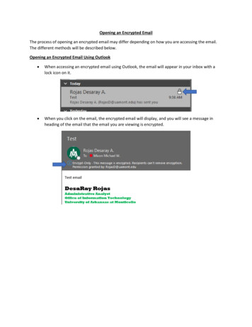
ing implementation of encoding and decoding operationsby means of simple exclusive-or operations.A preliminary construction of the Butterfly code waspresented earlier [14], and in this section we provide anew recursive construction of the code. Compared to theoriginal construction, the recursive approach has a simplified design that results in a simpler implementation.Furthermore, the recursive design partitions the problemin a way that allows for a better reuse of precomputedvalues, leading to better cache locality. Due to space limitations we omit the exhaustive cache behavior analysis.3.1C4a b d00d10 d01 d00;d11 d10d11 d00.d01 d00 d10 if k 2, then:a H(A);H(Dk ) Pk 1 [Pk 1 b H(Pk 1 B)]Pk 1 b B(A),B(Dk ) Pk 1 [a H(A) B(Pk 1 B)]D04a0a1a2a3a4a5a6a7d0 d1 d2 d3 d4 d5 d6 d7 Hc0 b0 a0c1 b1 a1c2 b2 a2c3 b3 a3c4 b4 a4c5 b5 a5c6 b6 a6c7 b7 a7Bd7 c3 b1 a0d6 c2 b0 a0 a1d5 c1 b1 a1 b3 a3 a2d4 c0 b0 a0 b2 a3d3 c3 b3 a3 c7 b7 a7 b5 a4d2 c2 b2 a2 c6 b6 a6 b4 a4 a5d1 c1 b1 a1 c5 b7 a7 a6d0 c0 b0 a0 c4 b6 a7and B over the same data Dk . Because of the double vertical flip, the recursion can be simplified, and encodingof Dk can be done by encoding A and Pk 1 B. In Figure 1we show an example of the recursive encoding for k 4.3.2Butterfly DecoderIn this section we show that Butterfly code can decodethe original data matrix when any two of the codewordcolumns are missing, and hence it is an MDS code.where A and B are 2k 2 k 1 boolean matrices, and aand b are column vectors of 2k 2 elements.Let Dkj be the jth column of Dk , j {0, . . . , k 1}.Therefore, the matrix Dk can be written as a vector of k0columns Dk (Dk 1k , . . . , Dk ). From a traditional erasurecode perspective each of the columns is an element ofGF(2k 1 ), and after encoding we get a systematic code0word Ck (Dk 1k , . . . , Dk , H, B), where H and B are twovector columns representing the horizontal and butterflyparities respectively.To describe how to generate H and B, we define twofunctions such that H H(Dk ) and B B(Dk ):D14b0b1b2b3b4b5b6b7how C4 can be computed by recursively encoding submatrix A(red highlight) and B (yellow highlight) from (1) and addingthe extra non-highlighted elements.Let Dk be a matrix of boolean values of size 2k 1 k,for k 2. Dk represents a data object to be encoded andstored in the distributed storage system. For the purposeof describing the encoding/decoding process, we represent Dk by the following components:a A,(1)Dk b Bd00d10D24c0c1c2c3c4c5c6c7Figure 1: Butterfly codeword for k 4, C4 . One can observeButterfly Encoder if k 2, then:1d0Hd111d0Bd11D34d0d1d2d3d4d5d6d7Theorem 1 (MDS). The Butterfly code can recover fromthe loss of any two columns (i.e. two erasures).Proof. The proof is by induction over the number ofcolumns, k. In the base case, k 2, one can carefullyverify from (2) and (3) that the code can recover fromthe loss of any two columns. The inductive step proceedas follows. Let’s assume that the Butterfly constructiongives an MDS code for k 1 columns, for k 2. We willprove that the construction for k columns is also MDS.We distinguish the following cases:(1) The two parity nodes are lost. In this case we encodethem again through H and B functions.(2) One of the parities is lost, along with one data column. In this case we can use the remaining parity nodeto decode the lost data column, and then re-encode themissing parity node.(3) Two data columns are lost, neither of which is theleftmost column. In this case we can generate from theparity columns the vectors H(A), B(A), by XOR-ing aand Pk 1 b. By using the inductive hypothesis, we can recover the top half of the missing columns (which is partof the A matrix). Similarly, we can generate by simpleXOR the values H(Pk 1 B) and B(Pk 1 B). By the induction hypothesis we can recover the bottom half of themissing columns (which is part of the B matrix).(4) The leftmost column along with another data columnDkj , j k 1, are lost. From the bottom half of the butterfly parity B(Dk ) we can obtain B(Pk 1 B), and then decode the bottom half of Dkj . From the bottom half of thehorizontal parity H(Dk ) we can now decode b. Following the decoding chain, from the top half of the butterfly(2)(3)(4)(5)where Pk represents a k k permutation matrixwhere the counter-diagonal elements are one andall other elements are zero. Notice that leftmultiplication of a vector or a matrix by Pk flips thematrix vertically.It is interesting to note that the double vertical flip in(4) is intentionally used to simultaneously compute H484 14th USENIX Conference on File and Storage Technologies (FAST ’16)USENIX Association
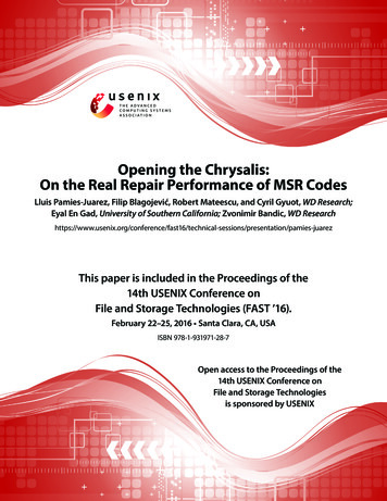
(3) First parity column H is lost All the remainingcolumns access and transfer their lower half, namely allthe elements with index i {2k 2 , . . . , 2k 1 1}. Thehorizontal parity over the systematic transmitted dataprovides the lower half of H, and the butterfly parity overD0k 1 , . . . , Dk 2k 1 XOR-ed with data from B will providethe top half of H.parity B(Dk ) we can obtain B(A), and then decode thetop half of Dkj . Finally, from the top half of the horizontal parity H(Dk ) we can obtain a.Theorem 2 (optimal regeneration). In the case of onefailure, the lost column can be regenerated by communicating an amount of data equal to 1/2 of the remainingdata (i.e., 1/2 of k 1 columns). If the lost column is notthe butterfly parity, the amount of communicated data isexactly equal to the amount read form surviving disks(i.e. optimal I/O access).(4) Second parity column B is lost In this case Dk 1kwill access and transfer its top half, while H will dothe same with its bottom half. The rest of the columnswill access all of their data, but they willD0k , . . . , Dk 2kperform XOR operations and only transfer an amount ofdata equal to half of their size. Each Dkj for j k 1will compute and transfer values equal to their contributions in the bottom half of B. Therefore a simple XORoperation between the data transferred from the systematic columns will recover the bottom half of B. Interestingly, computing a butterfly parity over the data transferred from Dkj , where j k 1, and XOR-ing it correspondingly with the bottom half of H will recover the tophalf of B.Due to space constrains we do not provide a proofhere. Instead, in the next section we provide the detailsrequired to regenerate any of the codeword columns.3.3Single Column RegenerationThe recovery of a single column falls under four cases.Note that in all of them, the amount of data that is transferred is optimal, and equal to half of the remaining data.Moreover, the amount of data that is accessed (read) isalso optimal (and equal to the data that is transferred),except in case (4) when we recover the butterfly parity.Case (1) is the most common. The data to be transferred is selected by algebraic expressions, but there aremore intuitive ways to understand the process. The indeces correspond to locations in the butterfly parity that donot require the additional elements; similarly, they correspond to inflexion points in the butterfly lines (v-points);also they correspond to 0 value for bit j 1 of the binary representation of numbers ordered by the reflectedGray code. Finally, the recovery in case (4) is based on aself-duality of the butterfly encoding.4Butterfly Codes in HDFSTo avoid recursion in Java, and possible performancedrawbacks due to non-explicit memory management,in HDFS we implement an iterative version of Butterfly [14]. Our implementation of Butterfly code in HDFSis based on publicly available Facebook’s Hadoop [2]version. In this section we provide implementation andoptimization details of our Butterfly implementation.4.1j(1) One column from {D1k , . . . , Dk 1k } is lost Let Dkbe the lost columnn. Every remaining column (systematic data and parities), will accesstransfer the el andiements in position i for which 2 j 1 0 mod 4, ori 3 mod 4. Let Dk 1 be the matrix of size (k 2 j 1Erasure Coding in HDFSWe use the Facebook HDFS implementation as a startingpoint for the Butterfly implementation. Facebook version of Hadoop contains two daemons, RaidNode andBlockFixer, that respectively create parity files and fixcorrupted data. Once inserted into the HDFS, all filesare initially replicated according to the configured replication policy. The RaidNode schedules map-reduce jobsfor erasure encoding the data. The encoding map-reducejobs take groups of k newly inserted chunks, and generate n k parity chunks, as presented in Figure 2. Theparity chunks are then stored back in HDFS, and thereplicas can be garbage collected. Lost or corrupteddata is detected and scheduled for repair by the BlockFixer daemon. The repair is performed using map-reducedecode tasks. Upon decoding completion, the reconstructed symbol is stored back to HDFS.1) 2k 2 formed from the transmitted systematic data,and Hk 1 , Bk 1 the columns of size 2k 2 formed from thetransmitted parity information. Let h H(Dk 1 ) Hk 1and b B(Dk 1 ) Bk 1 (i.e., we use butterfly encodingon the matrix Dk 1 ). The data lost from D j is now contained by h and b. More precisely, for i {0, . . . , 2k 2 },j 12 j i, and let r p mod 2 j . Thenlet p i 22 jDkj (p) h(i), and Dkj (p 2r 2 j 1) b(i).(2) Column D0k is lost In this case, the columnsD1k , . . . , Dk 1k , H will access and transfer the elementswith even index, and the column B will access and transfer the elements with odd index. Similar to case (1), thevectors h and b are obtained by applying butterfly encoding, and they provide the even, repectively odd, indexelements of the lost column.4.2Butterfly Implementation in HDFSThe encoding and repair process in HDFS-Butterfly follows a 4-step protocol: (i) in the first step the encoding/decoding task determines the location of the datablocks that are part of the k symbol message; (ii) the sec5USENIX Association14th USENIX Conference on File and Storage Technologies (FAST ’16) 85
(n,k) code in HDFS: k-1 k-2 D ( D D 0 Parity Blocks D ) HDFS Blocks, 64M eachk-1C ( D D 0 DH104x30x20x10x00P00P10P01P11P02P12For k 4, each HDFS block(4-1)contains 8 2 elements2 elements k-1 k-2 2Symbol Size: HDFS Data Blocks (symbols) B) Figure 2: Erasure Coding (k, n) in HDFS: (i) each symbol ispart of a separate HDFS block, (ii) k symbols represent a message, n symbols represent a codeword (initial message blocks parity blocks), (ii) In Butterfly, each symbol is divided inα 2k 1 elements.Elements usedfor recovering X12Symbol ID: 7x27x17x07P07P17Encoding Example (creatingelementsP00 and P10):P00 X30 X20 X10 X00P10 X37 X23 X11 X00Decoding Examplein case of Symbol 1 beinglost (recovering elementsX10 and X12):X10 X30 X20 X00 P00X11 X37 X23 X00 P10CORRUPTEDK-Symbol Message, k 4ParitiesEach column (block) resides on a different datanode.ond step assumes fetching the data to the node wherethe task is running; (iii) in the third step the encoding/decoding computation is performed, and finally (iv)the newly created data is committed back to HDFS.The first step, locating the data necessary for encoding/decoding process, is identical to the initial Facebookimplementation: position of the symbol being built isused to calculate the HDFS file offset of the entire ksymbol message/codeword (data necessary for buildingthe symbol). Calculating the offsets is possible becausethe size of the data being repaired equals the size of anentire HDFS block. In case the symbol being repairedis smaller than the HDFS block size, we rebuild all thesymbols contained in that HDFS block. Therefore, we always fetch k consecutive HDFS blocks – k-symbol message. The location of the parity symbols/blocks duringthe decoding is determined using similar approach.The second step, data fetching, is performed asynchronously and in parallel, from multiple datanodes. Thesize of the fetched data is directly related to the Butterfly message size, i.e. set of butterfly symbols spreadacross different datanodes. We allow the size of a Butterfly symbol to be a configurable parameter. We set thesymbol element size to symbol size/2k 1 . The advantage of tunable symbol size is twofold: (i) improved datalocality: size of the data chunks used in computation canbe tuned to fit in cache; (ii) computation - communication overlap: “rightszing” the data chunk allows communication to be completely overlapped by computation.The third step implements Butterfly encoding and decoding algorithms. While Section 3.2 presents formaldefinition of Butterfly, in Figure 3 we describe an example of Butterfly encoding/decoding schemes in HDFS.Figure 3 is intended to clarify the encoding/decodingprocess in HDFS-Butterfly through a simple example,and encoding/decoding of specific components mightbe somewhat different. Our encoding/decoding implementation is completely written in Java. While moving computation to a JNI module would significantly increase the level of applicable optimizations (includingvectorization), these benefits would be shadowed by thecost of data movements between Java and JNI modules.Elements to fetch in case of recovering column 1Elements to skip in case of recovering column 1Figure 3: Regenerating column 1 for HDFS-Butterfly withk 4. The line represents the elements that are xored to regenerate the first two symbols. The dark gray elements are thetotal required ones. White elements are skipped during communication.Our Java computation is aggressively optimized throughmanual loop reordering and unrolling but we saw little benefits from these optimizations. By instrumentingthe computational code, we found that the time spent inmemory management significantly outweighs the benefits computational optimizations. We also parallelizecomputational loops in the OpenMP fashion. The degreeof parallelization is a
Codes (RGC) and Locally Repairable Codes (LRC) are two family of erasure codes that can reduce the data and storage traffic during the regeneration. LRCs reduce the number of storage devices accessed during the regener-ation of a missing chunk. However, this reduction re-sults inlosing the MDSproperty, andhence, relaxingthe