Transcription
November 14, 2018Steve Dick, K1RF1
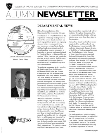
About Half-wave Antennas A half-wave antenna is a resonant radiating element with an electrical length ofone half-wave. Total length in feet. 468 / freq in Mhz. Its’ feed-point affects itsimpedance. High current, low voltage at center; low current high voltage atends. The most common half-wave antenna is the center-fed dipole, whoseimpedance is approximately 72 ohms. A dipole is basically a mono-bandantenna. It is sometimes used on its 3rd harmonic with coax, or usedmultiband as a doublet with balun, ladder line and wideband tuner.) If fed off center, say at 30%-70% point, impedance is approximately 200 ohmsand can be used on multiple bands with an antenna tuner. Works with a 4:1UNUN. See this link for more info. 4:1 impedance ratio is 2:1 turns ratio. If fed at the end (a.k.a EFHW), antenna impedance is in the 2000-4000 ohmsrange. It requires a high impedance matching device: Either a tapped resonantcircuit, a Zepp type coupling circuit, or a high impedance ratio UNUN (49:1 or64:1) It can be used on multiple bands. With a 49:1 or 64:1 UNUN, no tuningis required and no antenna tuner is required (or perhaps a “touch up” tunerwith up to 3:1 VSWR capability that many modern rigs have built-in.)2
What are the advantages of an EFHW fed withan UNUN compared to other wire antennas? Ease of installation. Only a single high point requiredMany configurations possible to suit your installation:Horizontal, Inverted V, Inverted L, Sloper, etcNo hanging feedline. Feed point is near the ground.Minimal ground system or counterpoise needed – thecoax feed itself can act as a counterpoiseResonant on 80/40/30/20/17/15/12/10m with lowVSWR. No tuner needed or just a 3:1 “Touch-up” tunerOne simple length adjustment – no interactionsbetween bands.Grounded at D.C. No static buildup.Shortened versions possible for limited area3
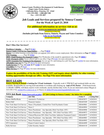
Multiband operation of a HalfWave Antenna If the half-wave antennacan be impedancematched on all of itsharmonics, you now havea multiband antenna.On the fundamentalfrequency, antennapattern is identical nomatter where you feed it.3.57 x 1 3.57 MHz3.57 x 2 7.14 MHz3.57 x 3 10.71 MHz3.57 x 4 14.28 MHz3.57 x 5 17.85 MHz3.57 x 6 21.42 MHz3.57 x 7 24.99 MHz3.57 x 8 28.56 Mhz80M40M30M20M17M15M12M10MBut a key characteristic that does change is the radiation patternon each harmonic. This IS affected by where the half-wave is fed.4
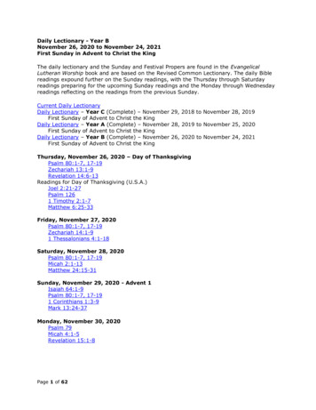
Conventional 1:4 and 1:9 UNUNs These UNUNs belongs to a class ofSecPridevices known as “transmission linetransformers”, which are formed byPri StrtSec Strtwinding bifilar turns, multi-filar turns,coaxial cable, or stripline cable (twostrips of the flat conductor with aPri Enddielectric material between the strips)Sec Endon a core having high permeability.Standard Transformer1:4 UNUNs (Zout 200 ohms) aretypically used for off-center-fed (OCF)dipoles, Zepps, and 43 foot multibandPri StrtSec Endverticals and random length (nonresonant) wiresSec StrtPri End1:9 UNUNs (Zout 450 ohms) aretypically used with random lengthnon-resonant wire antennasBalun DesignsAt low frequencies, like allTransmission line (twisted or parallel pair)transformers, they require adequateBifilar Wound Transmission Line Transformerprimary inductance at lowest freq.Transmission line transformers exhibit very wide bandwidth (1-54 MHz),high power capability (2-5KW), and high efficiency
Some Applications of the 4:1 UNUN Variants of the modern W3EDP ZeppCourtesy Tom, K1TA Off-Center-fed Antenna 160 through 6 meters! 4:1 balun is wideband andallows this to work. Requires wideband tuner:High SWR on even harmonicsand more feedline radiationCourtesy Balun DesignsThese usually require wide range antenna tuner6
Application of 9:1 UNUN Emergency Amateur Radio Club of Hawaii (EARCHI) marketed amatchbox-kit for a 6-40 mtr multi-band end-fed antenna. Uses nonresonant antenna (Recommended antenna wire length: 24-30 ft (60ft max) and powdered iron toroid, efficient transmission linetransformerT130-2Short Non-resonant antenna requires wide range antenna tuner7
High Impedance UNUN for EHFW antenna The UNUN has a high impedance ratio (49:1to 64:1) – not feasible to use transmission linetransformers whose practical limit is about16:1. It is a conventional transformer.Uses a ferrite toroidal core or cores (usuallyType 43 or type 52 material). Most 1:4 and 1:9transmission line UNUNs use powdered metalcores (such as -6) having much lowerpermeability, not suited for an EFHW UNUN.Bandwidths support about a 10:1 frequencybandwidth (3-30 MHz)Two important UNUN parameters are coreprimary inductance and efficiency.Less bandwidth (80-10M) and more lossy than the 4:1 or 9:1 UNUNs --But it still works fine and does the job.8
High Impedance UNUN for EHFW antennacont’d Primary inductance If primary inductance is too small at the low frequency end,Mismatch loss is significant and high VSWR results. If primary inductance is too high, the high frequencyperformance suffers and VSWR climbs at the high end. My rule of thumb: Inductive reactance (XL) should be in the88 ohm- 200 ohm range at the lowest frequency of use (XL 6.28 * F * L where (XL is inductive reactance in ohms, F isfrequency in MHz, and L is inductance in microhenrys. ). Thiscorresponds to 4-9 microhenrys at 3.5MHz or 2-4.5microhenrys at 7 MHz . Toroid primary inductance increases with size of toroid. TwoFT140 sized toroids have about the same inductance as asingle FT-240 sized toroid for the same number of turns. Toroid primary inductance is proportional to the number oftoroids.9
High Impedance UNUN for EHFW antennacont’d Efficiency Good designs should support efficiencies in the rangeof 80-90% For signal strength, It makes little difference. For dissipated power in the toroid(s), it makes a bigdifference. At 50 watts continuous and 75% efficient toroid(s),power dissipation in the toroid is 12.5 watts. At 50 watts continuous and 85% efficient toroid(s),power dissipation is 7.5 watts: 60% of the 75% efficienttoroid! CW duty cycle is 44% of continuous power SSB duty cycle is ! 25% of continuous power10
EFHW UNUN ConstructionI recommendat least 2 toroidsfor better efficiency,higher primaryinductance, andsplitting powerbetween toroidsNumber of turns number insidethe toroid stack.Crossover countsas one turn“Crossover”I recommend 2 type 43material for less than 250 watts for lowercost, Fair Rite P/N59430038013 type 52 material for 500-1000Whigher efficiency andhigher temperaturecapable. Fair RiteP/N 595200380111
EHFW Antenna ConstructionThe coax going to the UNUNcan serve as a counterpoise.A separate counterpoise wire isoptional.A choke balun is optional but must be installednear the rig, never near the ioncoilInverted L shown(Recommended).Never run antennawire next to a tower.Mount UNUN near topof tower instead.CoaxUNUNCounterpoise(optional)Mount UNUN1-10 ft from ground.Lower is better.Ground rod12
EFHW Counterpoise Current flowing into the antenna's end must be equaled, at that end point, by thesame amount of current flowing into a ground or counterpoise of some type. In spite of what some manufacturers will tell you, an end-fed 1/2 wave ALWAYShas a counterpoise. If you don't specifically provide one then the coax shield willact as the counterpoise.For a suspended counterpoise wire, the "ideal" length would be 1/4 wavelength.That would provide the lowest impedance on the common side of the feed pointand send the greatest amount of power into the antenna and minimize any RF onthe outside of the coax shield. Because the feed impedance on an end-fed 1/2wave is high, you can get away with a lot shorter counterpoise. The higher yourcounterpoise impedance, the more current will flow in the outside of the coaxshield, so its a trade off. Many get away with just using the coax shield as thecounterpoise (which some manufacturers advertise as "no counterpoise"). If you are near a wire fence, connect the ground to it. that makes a greatcounterpoise.If you have a good radial system, that will be a great counterpoise with minimalcurrents flowing on the coax.More info on counterpoise here13
Is a Choke Balun needed?Generally speaking, no. Depending onthe quality of your counterpoise, currentsplits between the counterpoise andcoax shield. You can use a choke balun, but it mustbe used at the rig end of the coax feed,NOT next to the UNUN or you will haveno counterpoise and the EFHW will notwork. 14
Ferrite MaterialsMaterialInitialPermeabilityRelative costCore lossCurieTemperatureCommentsFair Rite43800ModerateModerate 130degCPower 200W CWFair Rite52250HighLow 250degCPower 400WCWFair Rite61125HighLow 300degCDO NOT USEPermeabilitytoo low!Inductive partPermeability is actually complex- it has an inductive component (u’) anda resistive (lossy) component (u’’)Inductance typically gets smaller withfrequencyResistive partNever use powdered iron cores for aEFHW UNUN – permeability is way low.15
100pF compensation capacitor A 100pF capacitor is part of the UNUN antenna matching circuit. It is placedacross the primary of the UNUN to improve high frequency UNUN performance.Helps to compensative mainly for UNUN primary leakage inductance.The value of 100pF works well for most UNUNs, small or large, low power orhigh power.Typically uses a ceramic disk “blue cap” 3KV or more. These caps typically havea high current rating as they must handle several amps of RF current.Voltage rating can be increased by putting two 200 pF caps in series. Currentrating can be increased by putting two 47pF caps in parallel.For QRP rigs, a silvered mica 100pF 500V or 1KV rated cap is fine. SearchEBAY for 100pF silver mica, mouser.com, digikey.comSources of 100pF high voltage caps: EBAY (search for 100pF capacitor. Select a “blue cap”, 3KV or more Mouser P/N 81-DHR4E4C221K2BB (220pF, put two in series. Ceramic disk15KV rated, 1.23 each16
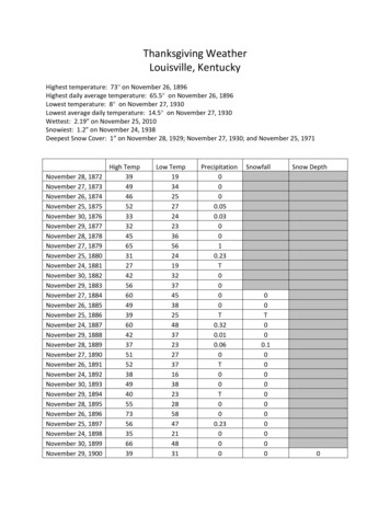
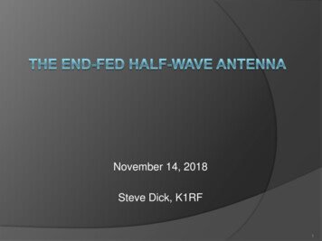
UNUN performance without andwith compensation cap (100pF)Increasing SWR due to UNUN leakage inductancesSWR improved in upper frequenciesSWR 3.8SWR 2.1Good SWR hereSWR climbs at low frequency end ifprimary inductance is too smallQRP Unun 3/21 wind Rload 2450QRP Unun 3/21 wind Rload 2450VSWR without 100pF capacitorVSWR with 100pF capacitorThe compensation capacitor compensates mainly for UNUN primaryleakage inductance and improves VSWR at upper end17
SWR plot on real antenna vs.resistive loadSWR plot looks verydifferent from a resistivetermination and typicallyimproves when driving areal antenna! That’s because if theantenna operatesslightly aboveresonance, it lookscapacitive. Thatcapacitance seriesresonates with ununsecondary leakageinductance, effectivelycancelling it out! 80 40 30 20 17 15 12 103.5 7 10.5 14 17.5 21 24.5 28Look Ma! Typical SWR plot withNo antenna tuner! Pretty nice!18
What does that small “compenation coil” do? The small coil, used on some commercial antennas, is usedto compensate the resonant point of the high bands. 1.5microHenrys 6T on 1.25” OD inch PVC form positionedat 78 inches from the feed point whether 80M EFHW or 40MEFHW. See Steve Ellington’s youtube video on this topic. Itlowers resonant point more and more at increasingfrequencies. 80M – lowers 22KHz40M – lowers 57 KHz20M – lowers 170 KHz15M – lowers 400 KHz10M – lowers 1 MHz Recommendation: For homebrew antennas, use coil if you’re primarilya CW operator, don’t use coil if you’re primarily a SSB operator. Orleave it out and use “touch-up” antenna tuner.19
If 80 meter resonant point is too low(for SSB) on 80 metersYou can add a small capacitor roughly inthe middle of the antenna wire. Value250pF-500pF. This is mounted at a highcurrent point. The “blue” ceramic highvoltage caps work. This cap has little effect on the higherfrequency bands. 20
Shortened EFHW AntennasUNUN side34uH coil: 90T, 110uH coil: 260 turns, 1mm (AWG #18) wire on 19m PVC tube.Adjust the long wire first for the high end bands. Then adjust the short wirefor the lowest band.Courtesy Jos Van den Helm, PA1ZP, RSGB February 2016.“A Three of Five Band End Fed Antenna”21
Adding 160 Meter Capabilityto an 80M-10M EFHW Antenna simplyDisconnect UNUN from coax feed. Connect jumper betweencoax feed and antenna, leaving UNUN “float”.The EFHW becomes a quarter wave antenna on 160 meters.Needs a good ground system to work properly.More into at:https://www.youtube.com/watch?v u SFS5FlM-w22
Air venting the UNUN housing Why Air Vent? Equalizes temperature and pressure Minimizes internal condensation Transformer runs coolerFor 100W rigs, two small 1/16” holes drilled onbottom of housing is sufficient For high power ( 500w) multiple screened airvents are recommended Commercial vent:Amphenol VENT-PS1YBK-N8001 2.90Some commercial UNUNs now use thistype of venting for pressure equalization 23
Use of 1,2,or 3 toroids Primary inductance is proportional to the number oftoroids. But you can’t simply add toroids for morepower handling. You also have to pay attention toefficiency and primary inductance – both are ferritematerial dependent.More than 1 toroid generally improves efficiency: Single FT240-43, 2T/14T wind is 66.5% efficient on 80Mand has inadequate primary inductance/high VSWR. For a100W rig on CW, dissipates 14.7 watts – much too high. Two FT240-43 2T/14T wind is 83.25% efficient, for a100W rig, dissipates 7.4W on CW (3.7W per toroid) withgood primary inductance/VSWR. Runs cool as theproverbial cucumber.Spend that extra few bucks, if necessary, for better performance24
Recommended UNUN configurationsApprox. Power rating, W Toroid size/matl Toroid qtyDigitalCWMFGRSecondary capacitorAWG Wire Size Primary turns TurnspFMFGR P/NEfficiency80M-10MFor:CommentSSBQRPlow cost, tiny,hard to wind,efficient512.520 non-standard1 Fair-Rite264362500222321100 90.1-93QRPrecommended1537.560 FT140-431 Fair-Rite264380270216321100 81.55-86.95QRP Plus2X power thansingle FT140-43and compact3075120 FT140-432 Fair-Rite264380270216214100 79.25-85.3100w recommended85212340 Ft240-432 Fair-Rite594300380114214100 84.1-88.1good for 40-10.high efficiency.Primaryinductance toolow on 80 metersHigh power (3uH)170425680 F240-522 Fair-Rite595200380114214100 98.2-88High power recommended3007501200 FT240-523 Fair-Rite595200380114213100 98.6-92Notes:1. All UNUNs listed have 80% efficiency and adequate primary inductance unless otherwise specified. Relative costtaken into account for recommendations.2. An alternate to the FT240-43 is a similar size toroid made by Laird Technologies with their type 28 material. 28B2400-000. Digikey P/N 240-2120NDThis material has higher permeability than Type 52 but lower permeability than type 43. It may be substituted for the FT240-43 and has similarefficiencies.3. The 100pF cap should be at least 3KV for 100 watt rigs, at least 6KV for high power. For QRP, a silvered mica cap, 500V-1KV rated can also beused.All UNUNs listed have 80% efficiency and adequate primaryinductance. Green are recommended for relative cost and ease of build25
Common Errors in buildinghomebrew EFHW UNUNs Using wrong toroid materials. Stay away from type 61 ferrite cores andany powdered iron cores like -2 or -6. Primary inductance too lowand it won’t work.Putting insulating tape on toroids. (doesn’t need it and degradesperformance by adding an air gap from wire to toroid. Ferrite toroidsused in these UNUNs have very high resistivity.Counting wrong number of turns (turns are turns that pass through theinside, including the crossover turn)Running parts of the antenna next to a metal tower (Put the UNUN attop of the tower, not at base with antenna next to tower)Putting a choke balun right next to the UNUN. If used, it should be nearthe rig or the antenna has no counterpoise and won’t work.Confusion about what antennas are appropriate for 4:1 and 9:1UNUNs. These are used with non-resonant antennas, not EFHWsPutting too much power into an undersized UNUN. Manymanufacturers have exaggerated claims for power handling capability.Toroids will overheat, SWR climbs as Curie temperature reached. Butthe toroid(s) will recover after cooling.26
Commercial EFHW antennas andUNUNs for EFHW antennas Recommended: https://myantennas.com/wp/ https://www.hyendcompany.nl/ https://www.gwhip.co.uk/ https://www.lnrprecision.com EndfedZ antennas https://qrpguys.com/ (for low cost QRP) Not Recommended: http://www.mfjenterprises.com/ MFJ198XXP Most stuff on EBAY27
QRPGuys.com QRP antennaLow cost ( 15.00)Clever design for portable use.Rated 2:1 SWR, 10 wattsBut Uses an FT82-43 toroid. According to my analysis, onlyabout 70-76% efficient and primary inductance on 80 and 40 too low.28
Some EFHW UNUNs I have builtQRP UNUN 90% efficient80-10M5W continuous,10W CW,20W SSBWorkhorse UNUN2 FT240-4384-88% efficient80-10M85 W continuous,212W CW.340W SSBTest setup with 2 FT140-43Small “QRP Plus” UNUN80-10M80-85% efficient30W continuous75W CW120W SSB29
Sources of materials Toroids – arrow.com, mouser.com,digikey.com, kitsandparts.com1 post stainless wire rope clip:Amazon.comEnamel wire: Amazon.com. Search on14 gauge copper magnet wire. TEMco,Essex good brands.Stainless steel ¼” hardware: HomeDepot, Lowes, mcmaster.com.4”X4”X2” PVC junction box (CarlonE989NNJ-CAR) Home Depot or LowesCable Tie Base Saddle Type MountWire Holder 100 pcs – Enay or Amazon100pF high voltage capacitors – EbayWire rope thimble (optional) Amazon ormarine supply house. Relieves strainaround eye bolt30
Resources Facebook group End Fed Half Wave Antennas 7000 membersReview of MyAntennas End Fed Half Wave Antenna 80-10 meters byJoel Halas, W1ZR, QST magazine, Mar. 2016 (Needs ARRL memberlogin)Endfed Halfwave antenna patterns (look under EFHW)Toroids.info Dimensions and inductance computationCalculate ferrite cored inductor parameters by Owen DuffyFerrite complex permeability tables for commonly used materialsAll Owen Duffy on-line calculatorsGood resource on End-fed AntennasW3EDP Multiband Zepp type antennaAll-band inverted L by Cebik before EFHW but shows antenna patternsGood insights into inverted L antenna advantages over doubletInfo on EFHW CounterpoiseVideo on protective vent31
About Half-wave Antennas A half-wave antenna is a resonant radiating element with an electrical length of one half-wave. Total length in feet. 468 / freq in Mhz. Its' feed-point affects its impedance. High current, low voltage at center; low current high voltage at