Transcription
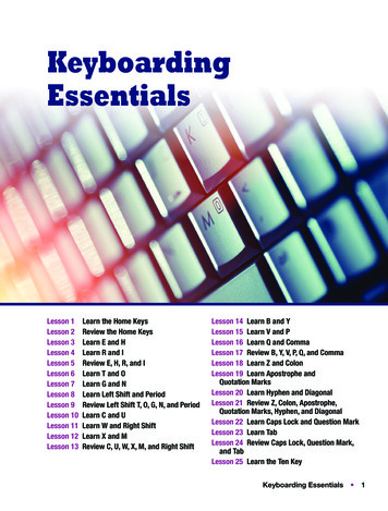
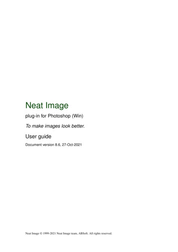
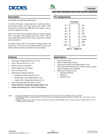
74HC5958-BIT SHIFT REGISTER WITH 8-BIT OUTPUT REGISTERDescriptionPin AssignmentsThe 74HC595 is an high speed CMOS device.( Top View )An eight bit shift register accpets data from the serial input (DS) oneach positive transition of the shift register clock (SHCP). Whenasserted low the reset function () sets all shift register values tozero and is indepent of all clocks.Data from the input serial shift register is placed in the output registerwith a rising pulse on the storages resister clock (STCP). With theoutput enable ( E asserted low the 3-state outputs Q0-Q7 becomeactive and present thAll registers capture data on rising edge and change output on thefalling edge. If both clocks are connected together the input shiftregister is always one clock cycle ahead of the output 11SHCPQ7710MR89GNDSO-16 / TSSOP-16FeaturesApplications Wide Supply Voltage Range from 2.0V to 6.0V Sinks or Sources 8mA at VCC 4.5V CMOS Low Power Consumption Schmitt Trigger Action at All Inputs Inputs Accept up to 6.0V ESD Protection Tested per JESD 22 Exceeds 200-V Machine Model (A115-A) Exceeds 2000-V Human Body Model (A114-A) Exceeds 1000-V Charged Device Model (C101C) Latch-Up Exceeds 250mA per JESD 78, Class II Totally Lead-Free & Fully RoHS Compliant (Notes 1 & 2) Halogen and Antimony Free. “Green” Device (Note 3)Notes:Q7SGeneral Purpose LogicSerial to Parallel Data ConversionCapture and Hold Data for Extended Periods of TimeAllow Simple Serial Bit Streams from a Microcontroller to Controlas Many Peripheral Lines as NeededWide Array of Products such as: Computer Peripherals Appliances Industrial Control1. No purposely added lead. Fully EU Directive 2002/95/EC (RoHS), 2011/65/EU (RoHS 2) & 2015/863/EU (RoHS 3) compliant.2. See https://www.diodes.com/quality/lead-free/ for more information about Diodes Incorporated’s definitions of Halogen- and Antimony-free, "Green"and Lead-free.3. Halogen- and Antimony-free "Green” products are defined as those which contain 900ppm bromine, 900ppm chlorine ( 1500ppm total Br Cl) and 1000ppm antimony compounds.74HC595Document number: DS35492 Rev. 4 - 21 of 11www.diodes.comNovember 2018 Diodes Incorporated
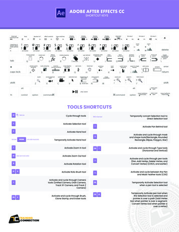
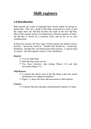
74HC595Pin DescriptionsPin NumberPin 41516Functional DiagramFunctionParallel Data Output 1Parallel Data Output 2Parallel Data Output 3Parallel Data Output 4Parallel Data Output 5Parallel Data Output 6Parallel Data Output 7GroundSerial Data Output14 DS11 SHCP10 MR8-Stage Shift RegisterQ7S12 STCP98-Bit Storage RegisterMaster Reset InputShift Register Clock InputStorage Register Clock InputEDSQ0Output Enable InputVCCSupply Voltage13 OE3-State OutputsQ0 Q1 Q2 Q3 Q4 Q5 Q6 Q7Serial Data InputParallel Data Output 0151234567Logic DiagramSTAGE 0DSDSTAGES 1 TO 6QDSTAGE 074HC595Document number: DS35492 Rev. 4 - 2Q1 Q2 Q3Q4 Q5 Q62 of 11www.diodes.comQ7November 2018 Diodes Incorporated
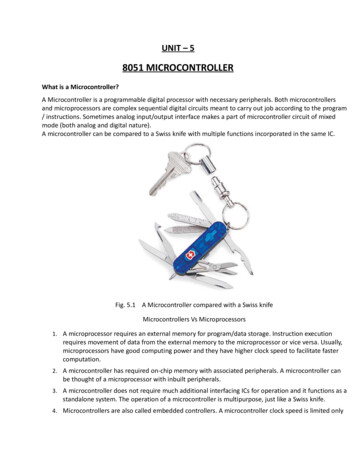
74HC595Functional Description and Timing DiagramControlInputSHCP STCPOutputDSQ7SQnNCFunctionLow-level asserted on MR clears shift register.Storage register is unchanged.XXLL LX XLL LLEmpty shift register transferred to storage register.XHL LZ XLH Q6SNCX LH NCQnS LH Q6SQnSShift register remains clear; All Q ouputs in Z state.HIGH is shifted into first stage of Shift Register Contents of eachregister shifted to next register.The content of Q6S has been shifted to Q7S and now appears ondevice pin Q7S.Contents of shift register copied to storage register. With output nowin active state the storage resister contents appear on Q outputs.Contents of shift register copied to output register then shift registershifted.H HIGH Voltage StateL LOW Voltage State LOW to HIGH TransitionX Don’T Care – High or Low (Not Floating)NC No ChangeZ High-Impedance ateQ7Q7S74HC595Document number: DS35492 Rev. 4 - 23 of 11www.diodes.comNovember 2018 Diodes Incorporated
74HC595Absolute Maximum Ratings (Note 4) (@TA 25 C, unless otherwise specified.)SymbolRatingUnitHuman Body Model ESD Protection2kVESD CDMCharged Device Model ESD Protection1kVESD MMMachine Model ESD ProtectionESD HBMVCCDescriptionSupply Voltage RangeVIInput Voltage RangeVoVoltage Applied to Output in High or Low StateIIKInput Clamp CurrentVI -0.5V200V-0.5 to 7.0V-0.5 to 7.0V-0.3 to VCC 0.5V-20mAIIKInput Clamp CurrentVI VCC 0.5V20mAIOKOutput Clamp CurrentVO -0.5V-20mAIOKOutput Clamp CurrentVO VCC 0.5V20mAQ7 Standard Output 25mAQn Bus Driver Outputs 35mAIOContinuous Output CurrentICCContinuous Current through Vdd or GND70mAIGNDContinuous Current through Vdd or GND-70mATJOperating Junction Temperature-40 to 150 CTSTGStorage Temperature-65 to 150 CPTOTTotal Power Dissipation500mWNote:4. Stresses beyond the absolute maximum may result in immediate failure or reduced reliability. These are stress values and device operation should bewithin recommend values.Recommended Operating Conditions (Note 5) (@TA 25 C, unless otherwise specified.)SymbolParameterConditionsMaxUnitSupply Voltage 2.06.0VVIInput Voltage 0VCCVVOOutput VoltageActive Mode0VCCVVCC 2.0V 1000VCC 4.5V 500VCCΔt/ΔVInput Transition Rise or Fall RateTAOperating Free-Air TemperatureVCC 6.0VNote:Min ns/V 400 -40 125 C5. Unused inputs should be held at VCC or Ground.74HC595Document number: DS35492 Rev. 4 - 24 of 11www.diodes.comNovember 2018 Diodes Incorporated
74HC595Electrical t VoltageLow-LevelInput Voltage(@TA 25 C, unless otherwise specified.)Test ConditionsVCCTA -40 C to 85 CTA 25 CMinTypMaxTA -40 C to 125 CUnitMinMaxMinMax 2.0V1.51.2 1.5 1.5 4.5V3.152.4 3.15 3.15 6.0V4.23.2 4.2 4.2 2.0V 0.80.5 0.5 0.5 4.5V 2.11.35 1.35 1.35 6.0V 2.81.8 1.8 1.82.0VVV1.92.0 1.9 1.9 4.5V4.44.5 4.4 4.4 6.0V5.96.0 5.9 5.9 IOH -4.0mA4.5V3.844.32 4.32 3.7 IOH -5.2mA6.0V5.345.81 5.81 5.2 Qn BusOutputsIOH -6.0mA4.5V3.844.32 4.32 3.7 IOH -7.8mA6.0V5.345.81 5.81 5.2 Low-LevelOutputVoltage2.0V 0IOL 20μA0.1 0.1 0.14.5V 00.1 0.1 0.16.0V 00.1 0.1 0.1IOL 4.0mA4.5V .150.33 0.33 0.4IOL 5.2mA6.0V .160.33 0.33 0.4Qn BusOutputsIOL 6.0mA4.5V .150.33 0.33 0.4IOL 7.8mA6.0V .160.33 0.33 0.4Input CurrentVI GND to 5.5V6.0V 0.1 1 1μAIOZOFF-StateOutputCurrentQn Internal High orLow6.0V 5 5 10μAICCSupplyCurrentVI GND or VCCIO 06.0V 8.0 80 160μACiInputCapacitanceVI VCC or GND6.0V 410 10 10pFHigh-LevelOutputVoltageVOHQ7S OutputVOLIIQ7S OutputIOH -20μAAll OutputsAll OutputsVVVo VCC or GNDOperating Characteristics (@TA 25 C, unless otherwise specified.)ParameterCpdPower DissipationCapacitance74HC595Document number: DS35492 Rev. 4 - 2Test Conditionsf 1 MHz All Outputs Switching-No Load5 of 11www.diodes.comVCC 5VTypUnit43pFNovember 2018 Diodes Incorporated
74HC595Switching CharacteristicsSymbol /ParameterPinsTest ConditionsfMAXMaximumFrequencySHCP orSTCPFigure 1SHCPHIGH orLOWtWPulse WidthFigure 1STCPHIGH orLOWFigure 1LOWFigure 1DS toSHCPFigure 1tSUSet-up TimeSHCP tpSTCPtHHold TimeDS toSHCPtRECRecovery ENEnable TimetDISDisable TimeSHCP toQ7SSTCP toQnto Q7SE to QnE to Qn74HC595Document number: DS35492 Rev. 4 - 2Figure 1Figure 1Figure 1Figure 1CL 50pFFigure 1CL 50pFFigure 1CL 50pFFigure 1CL 50pFFigure 1CL 50pFVCCTA 25 CMinTypMax-40 C to 85 CMinMax-40 C to 125 CMinMax2.0V930 4.8 4 4.5V3091 24 20 6.0V35108 28 24 2.0V7517 95 110 4.5V156 19 22 6.0V135 16 19 2.0V7511 95 110 4.5V154 19 22 6.0V133 16 19 2.0V7517 95 110 4.5V156 19 22 6.0V135 16 19 2.0V5011 65 75 4.5V104 13 15 6.0V93 11 13 2.0V7522 95 110 4.5V158 19 22 6.0V137 16 19 2.0V3-6 3 3 4.5V3-2 3 3 6.0V3-2 3 3 2.0V50-19 65 75 4.5V10-7 13 15 6.0V9-6 52 200132.0V 16011 2404.5V 1932 40 486.0V 1527 34 412.0V 55175 220 2654.5V 2035 44 536.0V 1630 37 452.0V 47175 220 2654.5V 1735 44 536.0V 1430 37 452.0V 47150 190 2254.5V 1730 38 456.0V 1426 33 382.0V 41150 190 2254.5V 1530 38 456.0V 1226 33 386 of r 2018 Diodes Incorporated
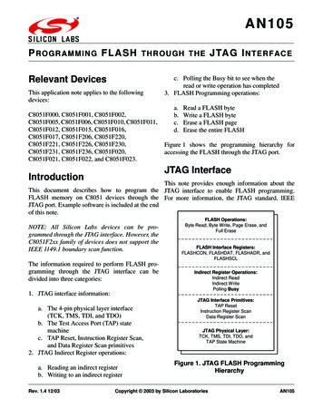
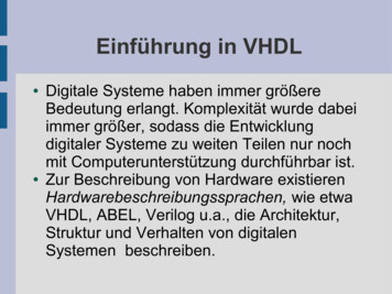
74HC595Parameter Measurement InformationRLFrom OutputUnder TestVLOADCL(see Note 0pFVItr/tf2.0VVCC4.5V6.0VVCC1/f MAXTimingInputtWVlInputVMVM0Vt SUVM0VDataInputthVCCVMVM0VMRtrecVoltage WaveformPulse Duration and Recovery TimeVoltage WaveformSet-up and Hold OutputVMVMOutputWaveform 1V LOAD VCC(see Note B)VOLtPHLtPLHVOHOutputVMVMOutputWaveform 2V LOAD GND(see Note B)tPZLtPLZVLOADVMVOL 10%VOLtPHZtPZHVMVOH - 10%VOH0VVOLVoltage WaveformEnable and Disable TimesVoltage WaveformPropagation Delay TimesInverting and Non Inverting OutputsNotes:A. Includes test lead and test apparatus capacitance.B. Output Waveform 1 depends on the internal QN node being low and behaves in this manner based on OE pin.Output Waveform 2 depends on the internal QN node being high and behaves in this manner based on OE pin.C. All pulses are supplied at pulse repetition rate 10 Hz.D. Inputs are measured separately one transition per measurement.E. tPLH and tPHL are the same as tPD.Figure 1. Load Circuit and Voltage Waveforms74HC595Document number: DS35492 Rev. 4 - 27 of 11www.diodes.comNovember 2018 Diodes Incorporated
74HC595Ordering Information74 HC 595 XXX - 13Logic Device74 : Logic PrefixHC : 2.0 V to 6.0 VFamilyNote:Function595 : 8-BIT SHIFTREGISTERWITH 8-BITOUTPUTREGISTERPart NumberPackage TSSOP-16PackageS16 : SO-16T16 : TSSOP-16Packing13 : 13" Tape & Reel7” Tape and eel (Note 6)QuantityPart Number Suffix2500/Tape & Reel-132500/Tape & Reel-136. The taping orientation is located on our website at ng Information(1) SO-16, TSSOP16( Top View )116489LogoYY : Year : 08, 09,10 WW : Week : 01 52; 5274HC595YY WW X XMarking ID1represents 52 and 53 weekX X : Internal Codes78Part Number74HC595S1674HC595T1674HC595Document number: DS35492 Rev. 4 - 28 of 11www.diodes.comPackageSO-16TSSOP-16November 2018 Diodes Incorporated
74HC595Package Outline Dimensions (All dimensions in mm.)Please see http://www.diodes.com/package-outlines.html for the latest version.Package Type: SO-16SEE DETAIL 'A'DE/2XE1/2EE1hYPIN 1hbecØ 0.760 Depth 0.050 0.0201(8x)A202A1R1RSEATING PLANEAGAUGE PLANESEATING PLANE0LDETAIL -b0.310.51-c0.100.25-D9.80 10.00-E5.906.10-E13.804.00-e1.27 BSCh0.150.250.20L0.401.27-L11.04 REFL20.25 BSCR0.07--R10.07--X3.945 REFY0.661 REFθ0 8 -θ15 15 -θ20 --All Dimensions in mmPackage Type: TSSOP-16E/2YEE1SEE DETAIL 'A'XPIN 1 x)be Ø0.760Depth0.050 0.02A2R1DRCASEATING PLANEA1LL2GAUGEPLANE L1DETAIL 'A'74HC595Document number: DS35492 Rev. 4 - 29 of 11www.diodes.comTSSOP-16DimMin Max TypA1.08A10.05 0.15A20.80 0.93b0.19 0.30c0.09 0.20D4.90 5.10E6.40 BSCE14.30 4.50e0.65 BSCL0.45 0.75L11.00 REFL20.25 BSCR / R1 0.09X1.350Y1.050θ0 8 θ15 15 θ20 All Dimensions in mmNovember 2018 Diodes Incorporated
74HC595Suggested Pad LayoutPlease see http://www.diodes.com/package-outlines.html for the latest version.Package Type: SO-16X1DimensionsCXX1YY1YValue (in mm)1.2700.6709.5601.4506.400CXPackage Type: TSSOP-16X1DimensionsCXX1YY1Y1Value (in mm)0.6500.3504.9001.4006.800Y1X74HC595Document number: DS35492 Rev. 4 - 2C10 of 11www.diodes.comNovember 2018 Diodes Incorporated
74HC595IMPORTANT NOTICEDIODES INCORPORATED MAKES NO WARRANTY OF ANY KIND, EXPRESS OR IMPLIED, WITH REGARDS TO THIS DOCUMENT,INCLUDING, BUT NOT LIMITED TO, THE IMPLIED WARRANTIES OF MERCHANTABILITY AND FITNESS FOR A PARTICULAR PURPOSE(AND THEIR EQUIVALENTS UNDER THE LAWS OF ANY JURISDICTION).Diodes Incorporated and its subsidiaries reserve the right to make modifications, enhancements, improvements, corrections or other changeswithout further notice to this document and any product described herein. Diodes Incorporated does not assume any liability arising out of theapplication or use of this document or any product described herein; neither does Diodes Incorporated convey any license under its patent ortrademark rights, nor the rights of others. Any Customer or user of this document or products described herein in such applications shall assumeall risks of such use and will agree to hold Diodes Incorporated and all the companies whose products are represented on Diodes Incorporatedwebsite, harmless against all damages.Diodes Incorporated does not warrant or accept any liability whatsoever in respect of any products purchased through unauthorized saleschannel.Should Customers purchase or use Diodes Incorporated products for any unintended or unauthorized application, Customers shall indemnify andhold Diodes Incorporated and its representatives harmless against all claims, damages, expenses, and attorney fees arising out of, directly orindirectly, any claim of personal injury or death associated with such unintended or unauthorized application.Products described herein may be covered by one or more United States, international or foreign patents pending. Product names and markingsnoted herein may also be covered by one or more United States, international or foreign trademarks.This document is written in English but may be translated into multiple languages for reference. Only the English version of this document is thefinal and determinative format released by Diodes Incorporated.LIFE SUPPORTDiodes Incorporated products are specifically not authorized for use as critical components in life support devices or systems without the expresswritten approval of the Chief Executive Officer of Diodes Incorporated. As used herein:A. Life support devices or systems are devices or systems which:1. are intended to implant into the body, or2. support or sustain life and whose failure to perform when properly used in accordance with instructions for use provided in thelabeling can be reasonably expected to result in significant injury to the user.B. A critical component is any component in a life support device or system whose failure to perform can be reasonably expected to cause thefailure of the life support device or to affect its safety or effectiveness.Customers represent that they have all necessary expertise in the safety and regulatory ramifications of their life support devices or systems, andacknowledge and agree that they are solely responsible for all legal, regulatory and safety-related requirements concerning their products and anyuse of Diodes Incorporated products in such safety-critical, life support devices or systems, notwithstanding any devices- or systems-relatedinformation or support that may be provided by Diodes Incorporated. Further, Customers must fully indemnify Diodes Incorporated and itsrepresentatives against any damages arising out of the use of Diodes Incorporated products in such safety-critical, life support devices orsystems.Copyright 2018, Diodes Incorporatedwww.diodes.com74HC595Document number: DS35492 Rev. 4 - 211 of 11www.diodes.comNovember 2018 Diodes Incorporated
X L L L L Empty shift register transferred to storage register. X X H L L Z Shift register remains clear; All Q ouputs in Z state. Q6SX L H NC HIGH is shifted into first stage of Shift Register Contents of each register shifted to next register. The content of Q6S has been shifted to Q7S and now appears on