Transcription
IET Generation, Transmission & DistributionResearch ArticleAdvanced power system partitioning methodfor fast and reliable restoration: toward a selfhealing power gridISSN 1751-8687Received on 12th November 2016Revised 14th July 2017Accepted on 30th July 2017doi: 10.1049/iet-gtd.2016.1797www.ietdl.orgAmir Golshani1 , Wei Sun1, Kai Sun21Departmentof Electrical and Computer Engineering, University of Central Florida, Orlando, FL 32816, USAof Electrical Engineering and Computer Science, University of Tennessee, Knoxville, TN 37996-2250, USAE-mail: Amir.Golshani@knights.ucf.edu2DepartmentAbstract: The recovery of power system after a large area blackout is a critical task. To speed up the recovery process in apower grid with multiple black-start units, it would be beneficial to partition the system into several islands and initiate theparallel self-healing process independently. This study presents an effective network partitioning algorithm based on the mixedinteger programming technique and considering the restoration process within each island. The proposed approachincorporates several criteria such as self-healing time, network observability, load pickup capability, and voltage stability limits. Itcan quickly provide multiple partitioning schemes for system operators to choose based on different requirements. Experimentalresults are provided to demonstrate the effectiveness of the proposed approach for IEEE 39-bus and IEEE 118-bus standardtest systems. Also, the sensitivity of the partitioning solution with respect to the various parameters is presented and discussed.Ultimately, the advantage of the proposed method is demonstrated through the comparison with other references.1IntroductionPower systems have been operated under stressed conditions due tothe rapid growth of electricity demand. This makes the systemmore vulnerable to cascading failures, which could lead to awidespread blackout. Despite all efforts to enhance power grids'resilience through various preventive and corrective actions, theoccurrence of large area blackout is still inevitable. Indeed, powerindustries around the world have witnessed several blackouts as aconsequence of natural disasters [1]. As a key component in a selfhealing smart grid, efficient recovery actions are critical in bothplanning and implementation phases to reduce the social andeconomic costs of power outages.The restoration process brings the system back to its normalstate. In the bottom-up restoration approach [2], restorative actionscan be initiated after the blackout incidence. The first stage is toassess the post-outage conditions of system components, as well asthe availability of generation sources and transmission paths. Onthe basis of the system topology and locations of black-start andnon-black-start units (BSUs and NBSUs), system operators mayprefer to partition the bulk power system into smaller islands forparallel restoration. After the partition, the recovery process isexecuted in each island independently and simultaneously, whichwill remarkably shorten the overall recovery time. Power systempartitioning can be applied to either prevent a cascading failureleading to a wide-area blackout or expedite the recovery process byenabling parallel restoration actions. The first case is also referredas controlled islanding, when the preventive control actions failedto avert the power system from entering to an emergency state,whereas the second case is applied after the occurrence of awidespread blackout, which is the main concern of this paper.The partitioning problem can be modelled as a multi-objectiveoptimisation problem, which determines appropriate partitioningpoints to divide the large area into multiple islands with a similarrestoration capability. Each island has sufficient generators, loads,and measurement devices while satisfying a set of operationalconstraints. Various partitioning methods have been proposed inthe literature. A BS zone partitioning algorithm based on the fuzzyclustering approach [3] and tabu search [4] have been developed.In [5], a recovery time index was defined to quantify the disparityof each subsystems' restoration time. It considers the electricaldistance as a characteristic indicator to describe the strength ofelectrical connection between two nodes. Graph-theory andIET Gener. Transm. Distrib. The Institution of Engineering and Technology 2017mathematical programming have been applied in developingefficient partitioning methods.First, graph-theory-based techniques have been used to modelthe topological and electrical characteristics of power systems. Anovel sectionalising strategy based on the un-normalised spectralclustering method was introduced in [6]. A two-step networkpartitioning strategy for parallel system restoration was proposed in[7]. To assign each NBSU to a proper island, a unit grouping modelwas developed to find the shortest path between BSUs and NBSUsin each island. A graph-theory-based sectionalising method wasproposed in [8] based on the cut-set matrix. It provides the shortlist of sectionalising strategies for system operators to deploy. Aconstrained spectral clustering-based network partitioningapproach was introduced in [9]. In this approach, a weighted graphwas constructed using the electrical distance of power network.The objective is to maximise electrical cohesiveness within theislands, or equivalently, creating islands with the stronglyconnected lines inside and weak external connections.Second, mathematical programming methods provide advancedmodelling and solution algorithms in the network partitioningproblem. In [10], a bi-level programming approach was proposedto solve the sectionalising problem with the objective ofminimising the outage duration of the critical loads. A wide-areameasurement system-based sectionalising method was proposed in[11]. They addressed the problem of observability of each formedisland by integrating the observability constraints in the proposedalgorithm. A sectionalising strategy based on the ordered binarydecision diagrams (OBDDs) for parallel power system restorationwas proposed [12]. They introduced a three-step OBDD searchmethod to improve solution efficiency. Voltage stability was alsochecked by simulation of critical contingencies.The network partitioning methods have been extensivelystudied in the aforementioned literature and the proposedapproaches can generate various partitioning solutions. However,more comprehensive and effective approach is needed which canoffer a deeper insight for decision makers to prioritise the solutionsbased on their qualities. To this end, a new network partitioningproblem formulation accounting for the restoration sequence isproposed whose objective function reflects the restoration time ofNBSUs and loads. Also, a number of linear constraints will beintroduced, so as to ensure the quality and feasibility of theresulting islands. Specifically, the observability, load pickup1
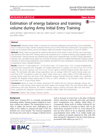
outages have been discussed in [19–21]. Optimal PMUs placementfor power system restoration has been discussed in [22]. OptimalPMU placement considering controlled islanding and normaloperation condition was proposed in [23]. After the formation ofeach island, a proper placement of PMUs can lead to a secureoperation of islands by providing synchronised measurementsignals for state estimators in control centres. Particularly,boundary buses through which transmission lines interconnectingtwo islands must be observable to guarantee a secure reconnection. This paper takes the optimal PMU placement as input,and also compares the impact of different PMU placement methodson the parallel restoration.To achieve a self-dependent island, the following criteria mustbe fulfilled within each island:Fig. 1 Simplified representation of network partitioning in bulk powersystemcapability, and voltage stability constraints are derived andintegrated into the network partitioning optimisation problem. Theproposed approach can generate a list of solutions from which thebest feasible solution can be derived and implemented in practise.2Parallel restoration conceptsThe recovery process after a blackout is consisted of several stages[13–15]: preparation and planning, BSU start-up, transmissionlines energisation, supplying cranking power to start NBSUs, andload pickup. This work focuses on the first stage of the recoveryprocess. At this stage, system operators obtain the current status ofpower grid including the availability of transmission lines, buses,BSUs, and NBSUs to prepare an effective restoration plan. Forinstance in [8], Quiros-Tortos et al. emphasised on collecting theinformation related to the system topology as well as theavailability of its elements right after blackout includingavailability of BSUs and interconnection assistance, the status ofthe non-BSU, the status of the lines and circuit breakers, and loadlevels. Moreover, the Pennsylvania–New Jersey–Marylandinterconnection restoration manual [16] discussed the completeassessment of post-blackout system for determining the systemstatus. When multiple BSUs are distributed in differentgeographical locations, system operators may initiate the parallelrestoration strategy to speed up the power system recovery process.In this approach, the bulk power system can be split into smallerislands in which a bottom-up restoration strategy can be performedconcurrently and independently.Fig. 1 highlights the network partitioning problem for parallelrestoration. First, the boundary transmission lines will bedetermined to isolate the islands. Each island incorporates at leastone BSU, one or multiple NBSUs, and loads with variouspriorities. Then, BSUs provide the cranking power for NBSUsthrough energising the shortest transmission lines between them.Next, load buses should be energised in a priority order. Loads withhigh priority must be restored first to mitigate the impact of poweroutage on hospitals, data-centres etc. Ultimately, different islandscan be re-connected and synchronised through a set of tie-linecircuit breakers to form a bulk power grid.One critical requirement for a successful parallel restoration isto ensure system observability before and after separation. Phasormeasurement units (PMUs) are placed in a bulk power system torender the whole system observable. The PMU placement problemhas been extensively investigated in [17–23] to find the minimumnumber and optimal locations of PMUs. The integer programming[17] and simulated annealing [18] techniques have beenimplemented to find the minimum number of PMUs to make thesystem observable. These methods only guarantee the systemobservability during the normal operation of power grid or under aspecific network topology. Moreover, optimal PMU placementsunder the loss of communication channels, PMUs, and branch2 Each island should include at least one BSU together with oneor several NBSUs [8, 9, 11]. In each island, the total generation capability should be morethan total load [7, 11, 12]. In other words, the maximumavailable generation should be greater than the maximumrestorable load; therefore, the remaining capacity can beassumed as reserve. Generators and loads should be distributed among islands suchthat to obtain a balanced parallel restoration with an optimisedoverall restoration time. After island formation, it would be preferable to have all buses,particularly boundary buses, observable to facilitatesynchronisation task when needed [8, 11]. After dis-connection of the boundary lines, the voltage stabilitylimits of other lines should not be violated [12]. Also, the powerflows through the transmission lines should not exceed theirthermal limits.In the present work, the above requirements are addressedthrough defining an appropriate objective function and constraints.3 Mathematicalformulationspartitioning problemofnetworkThe objective function of partitioning problem is to minimise theoutage duration of generators and loads as described in (1)minimise l s toni s αltload,,s S i Il L(1)i, swhere integer variable tonis on time of generator i in island s.l, sInteger variable tload shows the energisation time of load l in islands with the priority of αl. Sets of generators, loads, and islands are I,L, and S, respectively.3.1 Restoration time and islanding constraintsl, si, si, tInteger variables tonand tloadare defined in (2) and (3), where uonis a binary variable with 1 showing that generator i is on atl, t , sequals 1restoration time t, and 0 otherwise. Binary variable uloadonly when the load bus l is energised at restoration time t and theload belongs to island s. T denotes the set of restoration timesi, ston l, s tload (1 uoni t s) 1 i I, s S(2)l t s) 1 (1 uload l L, s S(3), ,t T, ,t TConstraints (4) and (5) assign each generator and load to only oneisland. Once assigned to a specific island, it will belong to thatisland for the entire restoration time s Si, t , suon 1i, t 1, suon i, t , suon i I, t T i I, t T, s S(4)IET Gener. Transm. Distrib. The Institution of Engineering and Technology 2017
s Sl, t , suload 1 l L, t Tl, t 1, sl, t , suload uload l L, t T, s S(5)in (14). The upper and lower limits of active and reactive power ofgenerators and loads are enforced in (15)–(18)θbi 03.2 Bus and line energisation constraintsThese constraints are defined to determine the binary variablesb, t, sk, t, sand ulineat each restoration time and in each island.ubusConstraint (6) denotes that NBSUs can become online at least onerestoration time after the energisation of their correspondinggeneration buses, bi. For the sake of simplicity, we neglect the startup duration of generators, which can be simply added to theproblem formulation. In (7), loads can be restored one restorationtime after the energisation of their respective load buses bl.Constraint (8) shows that transmission line mn remains deenergised if the buses at both ends are de-energised. Constraint (9)denotes that each transmission line mn can be energised onerestoration time after the energisation of its connecting bus m or n[24]. The set of transmission lines is denoted by K.b , t, sii, t 1, suon ubus i INBSU, bi B, t T, s S(6) l L, bl B, t T, s S(7) mn K, (m, n) B, t T, s S(8)b , t, sl, t 1, sluload ubusm(n), t, smn, t, suline ubusmn, t 1, sn, t, sm, t, suline ubus ubusTotal generation capability in each island should be greater than thetotal restorable loadb sb s Pload lubus Pgen iubusi,l,max,i Il L (bi, bl) B, s S(10)max, iwhere Pgendenotes maximum generation capability of unit imax, lshows the maximumlocated at generation bus bi and Ploadrestorable load.3.4 Power balance and load flow constraintsIn constraints (11) and (12), active and reactive power balances arei, si, senforced in each island, where Pgenand Qgenare scheduled activeand reactive powers of each generator in each island. Variablesk, sk, sPflowand Qfloware active and reactive power flows of transmissionline k connecting buses m and n, which is expressed in (19) and(20), respectivelyk sl si s Pflow Pload Pgen(11)l sk si s Qload Qflow Qgen(12)k Kl L,,i I,,,i Il L,k KIn constraint (13), the BSUs are considered as the slack generatorsin each island. Maximum and minimum voltage limits are enforced i I, s S(15)b, s i I, bi B, s S(16)min, i ii, smax, i iQgenubus Qgen Qgenubusb, s l L, bl B, s S(17)b, s l L, bl B, s S(18)max, l ll, subus Pload0 Ploadl, smax, l l0 Qload QloadubusLinearised model of AC power flow equations are presented in(19) and (20), where d mn is the cosine function approximation by aset of linear functions (more details can be found in [25]). Inconstraints (19) and (20), V n denotes voltage of bus n and θmn isangle difference between buses m and n. Parameters gmn, bmn, andbcmn are conductance, susceptance, and shunt susceptance oftransmission line between bus m and nmn, sPflow (2V m 1)gmn (V m V n d mn 2)gmn bmnθmn (n, m) B, mn K, s S, n mIET Gener. Transm. Distrib. The Institution of Engineering and Technology 2017(19)(see (20))3.5 Thermal limit constraintThe maximum active power flows through the line in each islandshould be restricted to the line thermal capacity mn K, s S(21)3.6 Observability constraintsConsidering the pre-specified PMU locations, to ensure theobservability of each island, the linear observability constraints aredeveloped and added to the partitioning problem. The impact onthe partitioning objective function will be discussed in this paper.Four different PMU placement methods are considered includingthe normal operating conditions and single branch outagecondition, each of which is studied with/without considering zeroinjection bus (ZIB) effect.We define an observability constraint for each resulting island sasb, sᾱsobs b, sl bb bB αbwbus bl B αbαlwbuslb, sb, sl bb bB αbubus bl B αlαbubus s S(22)lswhere parameter ᾱobsshows the degree of observability and variesbetween 0 and 1, which can be set by system operators. Parameterαb, ranging from 2 and 10, reflects the importance of the specificbus. For load buses, it equals to the load priority, αl, multiplied by10; and for generator buses, it takes the value of 10; otherwise, itb, sis 1 if bus b istakes the lowest priority of 2. Binary variable wbusobservable, and 0 otherwise. In PMU placement schemes 1 and 3b, s(can be referred in Table 1), wbuscan be derived from the inequalityconstraint (23)mn, sQflow (2V m 1)(bmn bcmn) gmnθmn (V m V n d mn 2)bmn (n, m) B, mn K,s S, n m(14)b, si, smax, i i0 Pgen Pgenubusb, s(13) m Bmn, smn mn, smn, sPmnf minuline Pflow P f maxuline3.3 Load and generation balance constraintsmax,V min V m V max mn K, (m, n) B, t T, s S(9)Constraints (2)–(9) are checked for each restoration time and dealtwith the sequential recovery process in each island, whereas thefollowing constraints are only checked at t T, after each islandformation. Thus, for notation brevity, t is dropped from theseconstraints. bi B, i IBSU(20)3
n, swbus nm Km nnm, sulinePMUm PMUn n B, s S(23)where binary parameter PMUn indicates the PMU status with 1showing that bus n has an installed PMU, and 0 otherwise.Constraint (23) implies that a specific bus n will remain observableafter partitioning either through its own PMU or from theneighbouring buses having the installed PMUs. This data will beavailable for a given network which can be derived from the PMUplacement schemes.To incorporate ZIB effect, constraint (23) needs to be modifiedas (24). Now, a certain bus can be observable either through theneighbouring buses or the ZIBs incident to that bus. Binarydecision variable hmn reflects the effect of ZIBs incident to bus n.Also, constraint (25) applies only to the ZIBs and enforces thatonly one bus incident to ZIB or the ZIB itself can be observablewhen the other buses are already observable. Parameter am is 1 ifbus m is a ZIB, and 0 otherwisen, swbus nm Km nnm, sulinePMUm nnn PMU h nm Km n nm Km nnm, s nmulineh(24) n B, s Snm, s nmulineh hmm am m B, s S(25)Note that constraints (24) and (25) contain the non-linear termnm, s nmulineh , which is the product of two binary variables. It can belinearised using (26), where pnm, s is an auxiliary binary variablenm, sand hnmequals to the product of two binary variables ulinepnm, s hnmnm, spnm, s ulinenm, sp nm, suline(26)nm h 1 nm K, s S3.7 Load pickup constraintsObjective function (1) ensures a quick energisation of generationbuses as well as loads with high priorities. This helps to expeditethe recovery process, but it would not be a sufficient condition forthe whole recovery period. For example, after load energisation,the load pickup capability should be distributed equally amongdifferent islands to speed up the overall recovery process.Therefore, an appropriate constraint should be incorporated into thepartitioning problem to ensure a balanced recovery.We define a new constraint to measure the load pickupcapability of each island with respect to the total load pickupcapability of the system in (27)ᾱspb, s sllΔPload/ l L Ploadubussl s S ΔPload/ l L Pload s S(27)where ᾱsp 1 indicates that the generation units are equallydistributed. It would be beneficial to have ᾱsp 1 for all islands;however, it seems impossible in practise. Our aim is to distributethe NBUs, so that the load pickup capability is distributed withrespect to the maximum restorable load in each island. In this way,islands with higher restorable load level acquire more load pickupcapability. The parameter ᾱps can be set by system operators.s, we need to compute theTo specify the value of ΔPloadmaximum frequency drop (nadir) after a load pickup step in eachisland. In this way, compared with the slow response and lowinertia generation units, generators with higher inertia constant andfaster active power ramping are capable of restoring larger blocksof loads. The general formulation of frequency dynamic in eachisland can be extracted from the swing equation [26] by neglectingthe damping coefficient of load as (28)f0dΔ f s(t)s (ΔPms ΔPload)sdt2HeqSB s S(28)where Δ f s (Hz) is the frequency deviation at the centre of inertia ins(s) denotes the total inertia in island s, ΔPms (MW) andisland s, HeqsΔPload (MW) represent changes in mechanical and electrical powerfollowing a load pickup value, and SB is the base power. A loadpickup will cause the frequency to decline at very first instancesafter a load pickup, due to the mismatch between mechanical andelectrical powers. The minimum permissible frequency (namelyfrequency nadir) in each island should not go below a certain limit.Otherwise, it will result in unfavourable under-frequency loadshedding activation. Thus, the maximum load pickup step must bespecified to assure that frequency nadir will not violate that limit.The frequency nadir in each island is a function of total inertia,governors' ramping rates, and amount of load being restoredsssΔ f s g(Heq, Req, ΔPload). As in load pickup stage, our emphasis ison the maximum drop of frequency (nadir) and the detaileddynamic model of generator has a very complex and non-linearnature. Therefore, a simplified model proposed in [27] is adoptedin this work. Note that, we assume that the governors' dead band isequal to zero. The frequency nadir time can be calculated from (29)ssdΔ f s(tnadir)ΔPloads 0 tnadir sdtReq s S(29)swhere Req(MW/s) is the sum of the ramping rate of all generatorsin island s. After finding the frequency nadir time, (30) shows therelationship between frequency nadir, inertia, governors' rampingrates, and the size of the contingency, which is equal to the totalsload pickup. With Δ f (0) 0, (30) can be rearranged for ΔPloadwhich yields (31)sΔ f s(tnadir) Δ f (0) 2s)f 0 (ΔPloadss2HeqSB 2ReqsssΔPload D ReqHeq s S s S(30)(31)where D (4SBΔ f s)/ f 0 will become a constant value afterchoosing the desired value of frequency nadir Δ f s (Hz) in eachssHeqwould reflectisland. Equation (31) implies that the value of Reqthe load pickup capability of island s which is related to thecharacteristics of generation units in that island.Table 1 Locations of PMUs in 39-bus under different PMU placement schemesNormal casePMU location (bus number)scheme 1 – ignore ZIBscheme 2 – include ZIBone line outagescheme 3 – ignore ZIBscheme 4 – include ZIB42, 6, 9, 10, 13, 14, 17, 19, 22, 23, 29, 34, 373, 8, 13, 16, 20, 23, 25, 29PMU location (bus number)1, 3, 5, 7, 9, 11, 13, 15, 17, 20, 21, 24, 26, 28, 30–383, 8, 16, 24, 26, 28, 30–38IET Gener. Transm. Distrib. The Institution of Engineering and Technology 2017
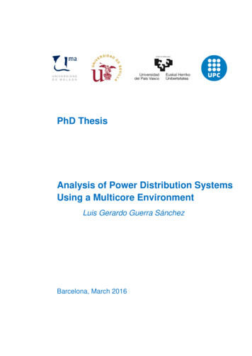
αvmn, s 24(Z mn) Qmn, s X mn2(V m X mn cos(θm θn)) 1(37)To linearise (37), the following equation and approximation can beapplied:(V m)2(cos(θm θn))2 (V m)223.8 Voltage stability constraint V m θm V n θnPmn, s jQmn, s mnmnR jXV n θnmn(32)where R is the line resistance and X is the line reactance.Separating the real and imaginary parts of (32) gives2V mV n cos(θm θn) (V n) RmnPmn, s X mnQmn, s V mV n sin(θm θn) X mnPmn, s RmnQmn, sPmn, s R Qm nmApplying the above approximation, the voltage stability constraintcan be written in (40). Note that, the voltage stability parameter,sᾱmnindicates the closeness of transmission lines to its collapsevpoint after partitioning. It can be set to the desired value (non-zero)or the value of this parameter should be kept 1 to maintain secureoperation of power grid. The closer to 1 indicates that the particularline is closer to its instability pointVm minimise ,,l L(41)(23)without ZIB(24) (26) with ZIB i I, (bi, bl) B, l L, mn K, (m, n) B, t T, s S(42)(34)(2) (22), (27), (31), (40),42(Rmn) mn, sQX mnRmnV mV n sin(θm θn) X mnQmn, s 0X mn(35)The condition for V n to have at least one solution is24(Z mn) Qmn, s X mnl s toni s αltloadsubject tonSubstituting Pmn, s from (34) into real part of (33) gives an equationof order two of V n (40)The proposed network partitioning optimisation problemformulation with/without considering the ZIB effect can besummarised ass S i I V V sin(θ θ )X mn(V n)2 V mV n cos(θm θn) 22(Z mn) Qmn, s cos 2(θm θn) 3 ,s44X mnᾱmnvAs stated in the linearised AC load flow constraint, the cosinefunction can be approximated by a set of linear functions, andQmn, s can be obtained from the load flow equations. Constraint(40) sets the lower value of sending end voltage whose upper levelis enforced in (14).(33)Rearranging the imaginary part for Pmn, s givesmn, s(39)3.9 Partitioning optimisation problemmnmn(38)2(V m)(V m) cos 2(θm θn) 2V m2213 cos 2(θm θn) 22Fig. 2 Sample 2-bus system connected via a π model of transmission lineIt is imperative to measure the voltage stability margin aftersplitting the bulk network into several islands. Thus, we propose alinear voltage stability constraint to be integrated into thepartitioning problem to maintain certain level of stability marginafter partitioning. There are different methods used in the previousworks on the subject of voltage stability assessment and reportedvarious criteria as the voltage stability indicators. Among thoseworks, line stability margins have been introduced in [28, 29] todetermine the weakest lines in the system. Here, by taking theadvantage of linearised AC power flow and the receiving endreactive power equation of transmission line, a linear voltagestability constraint is proposed.Assume π model of transmission lines connected two buses mand n, as shown in Fig. 2. Sending and receiving buses voltagesand angles are depicted by V m and V n, Qmn, s shows the linereactive power before the charging capacitor at the receiving end.Then, the current flowing between buses m and n is written as1 cos 2(θm θn)22(V mRmn sin(θm θn) V m X mn cos(θm θn)) 1(36)The left-hand side of the inequality (36) can be defined as thevoltage stability index with the value between 0 and 1. Thefollowing approximations have been applied to derive a linearequation for voltage stability constraint: in transmission lineusually X mn Rmn and sin(θm θn) θm θn is a very smallvalue; therefore (36) can be approximated as:IET Gener. Transm. Distrib. The Institution of Engineering and Technology 2017Numerical resultsIn this section, we present the experimental results to demonstratethe effectiveness of the proposed partitioning method. We havetested the proposed algorithm on two IEEE standard cases: 39-busand 118-bus systems. The data of each test case were taken from[30], assuming that voltage limits at all buses vary between 0.95and 1.05 pu. The minimum frequency decline after a load pickupstep is restricted to 59.6 Hz. Our model was implemented using C with IBM ILOG CPLEX 12.6 on a personal computer with IntelCore i5 central processing unit at 3.30 GHz and 8 GB randomaccess memory.4.1 IEEE 39-bus system simulation results and analysisIEEE 39-bus system contains ten generators with nominalgenerating capacity of 6150 MW and maximum restorable load of5950 MW. Generators G10 and G3 are the BSUs and the othergenerators serve restoration as the NBSUs. We apply the proposedpartitioning method to split the system into two islands. Table 1indicates the optimal locations of PMUs for different schemes. Inscheme 3, where a single line outage contingency has been5
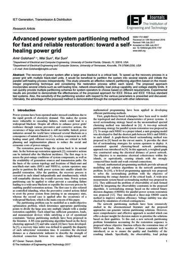
Table 2 Partitioning solutions for IEEE 39-bus system withsdifferent ᾱobssCaseObjective functionSchemeᾱobsFig. 3 Sensitivity of objective function to the observability constraint inscheme 11infeasible2180.3scheme 1scheme 2scheme 3scheme 4scheme 1scheme 2scheme 3scheme 4Island 1Island 0scan observe that the maximum values of ᾱobsusing scheme 1 canreach to 0.94 and 1.0 for islands 1 and 2, respectively. However,this will bring higher objective function value, which causes morerecovery time of the whole system. It is important to note that twoinfeasible regions can be observed in Fig. 3. The infeasible regionon the left-hand side is caused by the shortage of reactive powersources, which results in a non-convergent load flow, whereas theinfeasible solution on the right-hand side implies that adoptingPMU placement scheme 1 cannot render both islands fullyobservable.Fig. 4 Sensitivity of objective function to parameter ᾱspFig. 5 Values of voltage stability index αvmn, s for candidate lines in IEEE39-bus systemconsidered and ZIB effect is neglected, the largest number ofPMUs among all four schemes should be installed to render fullsystem observable, whereas the smallest number of PMUs to makesystem observable under normal condition has been obtained inscheme 2. Note that the PMU placement problem usually givesmultiple solutions with the same objective function value. Here, weonly picked one of those solutions as i
3.1 Restoration time and islanding constraints Integer variables ton i,s and tload l,s are defined in (2) and (3), where uon i,t is a binary variable with 1 showing that generator i is on at restoration time t, and 0 otherwise. Binary variable uload l,t,s equals 1 only when the load bus l is energised at restoration time t and the load belongs .