Transcription
The HubbleODditNovember 1930National Aeronautics andSpace Administration-TelescopeFailure Rewrt
Tne Hubble Space TelescopeOptical Systems Failure ReportNovember 1WNational Aeronautics andSpace Administration
Dr. Lew Allen, ChairmanDirector, Jet Propulsion LaboratoryLe rDr. o hinge1Professor of Astronomy, Steward ObservatoryUniversity of Arizona e a dOptics, r a a , a c 2 e c h nDivisionolo NASMGoddard Space Flight Center r x e o r g A.e odne AAssociate Administrator for Safety and Mission QualityNASA HeadquartersProfessor Robert R. ShannonDirector, Optical Sciences CenterUniversity of ArizonaMr. Charles P. spoelh&Vice President (Retired), Eastman Kodak Company
The Hubble Space Telescope (HST) was launched aboard the Space ShuttleDiscovery on April 24, 1990. During checkout on orbit, it was discovered that thetelescope could not be properly focused because of a flaw in the optics. The HSTProject Manager announced this failure on June 21, 1990. Both of the highresolution imaging cameras (the Wide Fieldplanetary Camera and the Faint ObjectCamera) showed the same characteristic distortion, called spherical aberration, thatmust have originated in the primary mirror, the secondary mirror, or both.The National Aeronautics and Space Administration (NASA) AssociateAdministrator for the Office of Space Science and Applications then formed theHubble Space Telescope Optical Systems Board of Investigation on July 2, 1990, todetermine the cause of the flaw in the telescope, how it occurred, and why it wasnot detected before launch. The Board conducted its investigation to includeinterviews with personnel involved in the fabrication and test of the telescope,review of documentation, and analysis and test of the equipment used in the. fabrication of the telescope's mirrors. The information in this report is basedexclusively on the analyses and tests requested by the Board, the testimony givento the Board, and the documentation found during this investigation.Continued analysis of images transmitted from the telescope indicated thatmost, if not all, of the problem lies in the primary mirror. The Board'sinvestigation of the manufacture of the mirror proved that the mirror was made inthe wrong shape, being too much flattened away from the mirror's center (a.0.4-wave rms wavefront error at 632.8 nm). The error is ten times larger than thespecified tolerance.The primary mirror is a disc of glass 2.4 m in diameter, whose polished frontsurface is coated with a very thin layer of aluminum. When glass is polished,small amounts of material are worn away, so by selectively polishing differentparts of a mirror, the shape is altered. During the manufacture of all telescopemirrors there are many repetitive cycles in which the surface is tested by reflectinglight from it; the surface is then selectively polished to correct any errors in itsshape. The error in the HST's mirror occurred because the optical test used in thisprocess was not set up correctly; thus the surface was polished into the wrongshape.The primary mirror was manufactured by the Perkin-Elmer Corporation, nowHughes Danbury Optical Systems, Inc., which was the contractor for the OpticalTelescope Assembly. The critical optics used as a template in shaping the mirror,the reflective null corrector (RNC), consisted of two small mirrors and a lens. The
RNC was designed and built by the Perkin-Elmer Corporation for the HST Project.This unit had been preserved by the manufacturer exactly as it was during themanufacture of the mirror. When the Board measured the RNC, the lens wasincorrectly spaced from the mirrors. Calculations of the effect of suchdisplacement on the primary mirror show that the measured amount, 1.3 mm,accounts in detail for the amount and character of the observed image blurring.No verification of the reflective null corrector's dimensions was carried out byPerkin-Elmer after the original assembly. There were, however, clear indicationsof the problem from auxiliary optical tests made at the time, the results of whichhave been studied by the Board. A special optical unit called an inverse nullcorrector, designed to mimic the reflection from a perfect primary mirror, was builtand used tpalign the apparatus; when so used, it clearly showed the error in thereflective null corrector. A second null corrector, made only with lenses, was usedto measure the vertex radius of the f i s h e d primary mirror. It, too, clearly showedthe error in the primary mirror. Both indicators of error were discounted at thetime as being themselves flawed.\,'1The Perkin-Elmer plan for fabricating the primary mirror placed completereliance on the reflective null corrector as the only test to be used in bothmanufacturing and verifying the mirror's surface with the required precision.NASA understood and accepted this plan. This methodology should have alertedNASA management to the fragility of the process and the possibility of gross error,that is, a mistake in the process, and the need for continued care andconsideration of independent measurements.The, design ofthe telescope and the measuring instruments was performed wellby skilled optical scientists. However, the fabrication was the responsibility of theOptical Operations Division at the Perkin-Elmer Corporation (P-E), which wasinsulated from review or technical supervision. The P-E design scientists,\\&nagement, and Technical Advisory Group, as well as NASA management andNASA review activities, all failed to follow the fabrication process with reasonablediligence and, according to testimony, were unaware that discrepant data existed,although the data were of concern to some members of P-E's Optical OperationsDivision. Reliance on a single test method was a process which was clearlyvulnerable to simple error. Such errors had been seen in other telescopeprograms, yet no independent tests were planned, although some simple tests toprotect against major error were considered and rejected. During the critical timeperiod, there was great concern about cost and schedule, which hrther inhibitedconsideration of independent tests.The most unfortunate aspect of this HST optical system failure, however, is thatthe data revealing these errors were available from time to time in the fabrication
process, but were not recognized and fully investigated at the time. Reviews wereinadequate, both internally and externally, and the engineers and scientists whowere qualified to analyze the test data did not do so in sufficient detail.Competitive, organizational, cost, and schedule pressures were all factors inlimiting full exposure of all the test information to qualified reviewers.
CONTENTSIINTRODUCTIONI1THE HUBBLE SPACE TELESCOPE MISSIONI11PROGRAM HISTORY AND MANAGEMENTA.ResponsibilitiesB.EnvironmentIVOPTICAL TELESCOPE ASSEMBLYA.HST Optical DesignB.Optical TestingC.Null Correctors and OpticsD.PolishingE.Final TestsVTHE FAILUREVIIDENTIFICATION OF THE FAILUREOnboard DataA.B.Sources of ErrorVIIHOW THE ERROR OCCURREDA.IntroductionB.Metering Rod MeasurementsVIIIQUALITY ASSURANCE OBSERVATIONSIXWHY THE ERROR WAS NOT DETECTED PRIOR TO FLIGHTA.Factual StatementsB.Judgmental StatementsXLESSONS LEARNEDA.Identify and Mitigate RiskB.Maintain Good Communication Within the ProjectC.Understand Accuracy of Critical MeasurementsD.Ensure Clear Assignment of ResponsibilityE.Remember the Mission During CrisisF.Maintain Rigorous DocumentationGLOSSARY
APPENDIX ACHARTER AND MEMBERSHIP OF THE BOARDA-1APPENDIX BSUMMARY OF PROCEEDlNGSHST Independent Optical ReviewAttachment 1Panel FindingsB-1APPENDIX CTUTORIAL ON SPHERICAL AND COMA ABERRATIONA. IntroductionB. Spherical AberrationC. Correcting for Spherical AberrationD. Field of ViewE. Coma AberrationF. Correcting Coma and Spherical AberrationsAcross the FieldAPPENDIX DDESCRIPTIVE SUMMARY OF INTERFEROGRAMSA. Final Test of the Primary MirrorB. Refractive Null Corrector Test of the Primary MirrorC. Inverse Null Corrector FringesD. Secondary Mirror Test InterferogramAPPENDIX EHST PERFORMANCE BASED ON AS-BUILT DATAB-1-1D-1D-1D-5D-6D-11E-1Tables2-1.HST scientific instrument specifications.2-3E-1.HST OTA paraxial design parameters.E-2E-2.HST OTA paraxial as-built parameters.E-32-1.Optical Telescope Assembly.2-23-1.Hubble Space Telescope responsibilities.3-23-2.MSFC's Hubble Space Telescope responsibilities.3-34-1.Two-element refractive null corrector.4-34-2.Reflective null corrector.4-44-3.Inverse null corrector inserted below the reflective null corrector.4-55-1.Encircled energy versus arcsecond radius of imageproduced by the HST.viii
Planetary Camera images versus computer simulations.Comparison of 1982 and 1990 inverse null corrector data.The 1990 spacing measurement between the field lensand the lower mirror of the reflective null corrector, usingan optical test.The 1330 spacing measurement between the lower mirrorvertex and the field lens of the reflective null corrector,using a mechanical technique.Position of metering rods used to space opticalelements in the reflective null corrector.Metering rod (B rod) used to space the field lensand the center of curvature of the lower mirror inthe reflective null corrector.Metering rod in position between the field lensand the center of curvature of the lower mirror inthe reflective null corrector.Displacement due to the interferometer focusing onthe field cap instead of the metering rod.Top view of the field cap, showing the aperture and thearea where the antireflective coating had broken away.Light-path comparison between spheric and aspheric mirrors.Image distortion due to spherical and coma aberration.The HST's Ritchey-Chretien optical system.Image-plane enlargement of the HST Ritchey-Chretienoptical system.RNC interferogram of the primary mirror, takenin February 1982.RvNC interferogram of the primary mirror, takenin May 1981.INC interferogram of the reflective null corrector, takenin February 1981.Hindle Shell interferogram of the secondary mirror,taken August 31, 1981.
The rough grinding operation for the Hubble Space Telescope began inDecember 1978, at the Perkin-Elmer Corporation, in Wilton, Connecticut. Themirror was then transferred to Perkin-Elmer in Danbury, Connecticut, now HughesDanbury Optical Systems, Inc. (HDOS), where polishing was completed in April1981, and the mirror was accepted as ready for reflective coating. The final postcoating test was made in February 1982.Approximately two months after launch, on June 21, 1990, the Hubble SpaceTelescope Project Manager announced that there was a major flaw in one or bothof the mirrors in the Optical Telescope Assembly. Dr. Lennard Fisk, AssociateAdministrator for the Office of Space Science and Applications, in accordance withthe procedures of the HST Contingency Plan, established the Hubble SpaceTelescope Optical Systems Board of Investigation to determine the relevant facts.A copy of the Board's charter, incorporated in a letter of authorization to theChairman, and a list of the members of the Board are presented in Appendix A ofthis report.The Board, in accordance with its charter, impounded all relevantdocumentation and equipment at the HDOS facility. With the assistance of HDOSpersonnel and NASA HST Project and Program management, the Board revieweddocuments, interviewed personnel, and analyzed and tested the equipment usedduring the fabrication of the mirrors.The first meeting of the Board was held in Washington, DC on July 5 and 6,1990, and the subsequent meetings were held at HDOS. A summary of all theBoard meetings and attendees can be found in Appendix B.The investigation was quickly directed to the fabrication and testing of theprimary mirror. The test equipment used during the final shaping and polishing ofthe primary mirror was found in 1990 in essentially the same configuration as ithad been when used in 1980 through 1982.Another investigating body, the Independent Optical Review Panel, was formedby the HST Project to examine the on-orbit data and recommend actions tomaximize the scientific utility of the HST. One of the principal concerns of theIndependent Optical Review Panel is the impact of the spherical aberrationdiscovered in the HST primary mirror. The results and findings of the HST OpticalSystems Board of Investigation will undoubtedly assist the Independent Optical
Review Panel in its work. (An early report of the Panel's findings is included inAppendix B.)This report of the Board's investigation describes the results of the analysis andtest of the equipment used during fabrication and sets forth the conclusions whichcan be drawn. It is difficult to reconstruct the exact events of the time, particularlysince the status of the documentation is poor. It is also difficult to consider fairlythe pressures of the time in question when cost and schedule were issues of crisisproportions. Therefore, the Board's judgments clearly benefit from hindsight, withthe clear knowledge that an error occurred and should not have occurred.
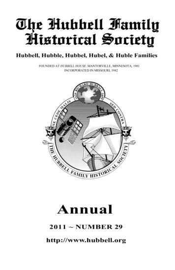
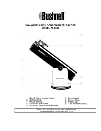
lXEB E SPACE TELESCOPE MISSIONThe HST was designed to be the first of the great space observatories. It waslaunched aboard the Space Shuttle and placed in an Earth orbit approximately 607kilometers in altitude. The expected life of the telescope is about 15 years, withinstrument changeouts every 3 to 5 years.The goal of the mission is to extend our knowledge of the universe. A spacebased telescope has the advantage of being in an environment free of theturbulence and absorption of the Earth's atmosphere. Prior to this mission,astronomical telescopes in space, such as the Einstein Observatory (HEAO-2) andthe Infrared Astronomical Satellite (IRAS), had been designed to explore newwavelength bands not transmitted through the atmosphere. The HST was the firstspace telescope designed to overcome the blurring of images caused by theatmosphere. The inherent resolution of a precisely made telescope is inproportion to its diameter, and the large 2.4m aperture of HST promised imagesten times sharper than the best images from the ground.At the heart of the Optical Telescope Assembly (OTA) is a 2.4-m Ritchey-Chretien telescope with a focal ratio of f/24. The optical range of the HST extendsfrom 1,100 to 11,000 angstroms, and the performance quality in the ultraviolet isunique. Figure 2-1 illustrates the OTA.Eight instrument packages are attached to the HST: two cameras (WideField/Planetary Camera and Faint Object Camera), two spectrographs (Faint ObjectSpectrograph and High-Resolution Spectrograph), one photometer (High-SpeedPhotometer), and three fine guidance sensors. Each fine guidance sensor packagealso contains a wavefront sensor. Table 2-1 lists the HST and scientific instrumentspecifications.
APERTURE DOORSECONDARYINCOMING LIGHT e 2-1. Optical Telescope Assembly.(IMAGE FORMEDHERE)
Table 2-1. HST scientific instrument specifications.11,500 kgField of ViewPointing AccuracyMagnitude RangeWavelength RangeAngular ResolutionPrincipal InvestigatorRitchey-Chretien design Cassegrain telescope57.6 m folded to 6.4 m2.4 m in diameter0.3 m in diameterSee instruments and sensors below0.007 arcsec for 24 hr5-29 mv1,10&11,000 angstroms0.1 arcsec at 6,328 angstroms611 km (330 nrni) inclined 28.5' from equatorF. D. Macchetto, European Space Agency (ESA)ESA Dornier, Matra Corp.)Field of ViewMagnitude RangeWavelength RangeRadiator: 0.8 x 2.2 mJ. A. Westphal, California Institute of TechnologyJet Propulsion LaboratoryfA2.9 0;f/30 @)160, 66 arcsec29-28 mv1,150-1 1,000 angstroms0.9 x 0.9 x 2.2 mJ. C. Brandt, NASAIGoddard Space Flight CenterBall Aerospace2 arcsec2 target, 0.25 arcsec2 science2,00&100,00017-11 mv
Table 2-1. EST scientific instrument specifications (continued).WeightDimensionsPrincipal InvestigatorContractorAperturesResolutionMagnitude RangeWavelength Range306 kg0.9 x 0.9 x 2.2 mR. J. Harms, NASMArnes Research CenterMartin Marietta Corporation0.1-4.3 arcsec2250, 1,30019-26 m,1,100-8,000 angstromsWeightDimensionsPrincipal InvestigatorContractorAperturesResolutionMagnitude RangeWavelength Range270 kg0.9 x 0.9 x 2.2 mR. Bless, University of WisconsinUniversity of Wisconsin0.4, 1.0, 10.0 arcsec2Filter-defined 24 m,1,2067,500 angstromsWeightDimensionsContractorAstrometric ModesPrecisionMeasurement SpeedField of View218 kg0.5 x 1 x 1.6 mPerkin-Elmer CorporationStationary and moving target, scan0.002 arcsec210 stars in 10 minutesAccess: 60 arcmin2Detect: 5 arcsec24-18.5 m,4,6767,000 angstromsMagnitude RangeWavelength RangeInformation provided by Lockheed Missiles and Space Company, Inc.
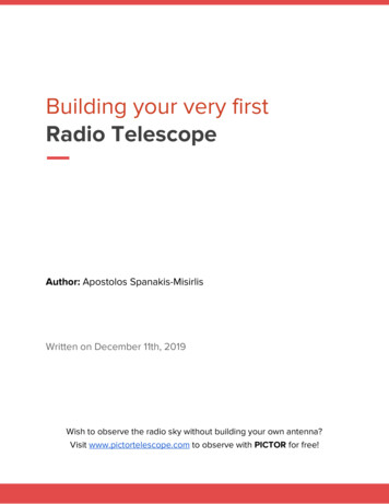
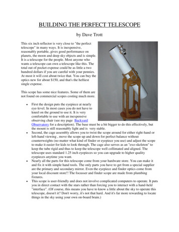
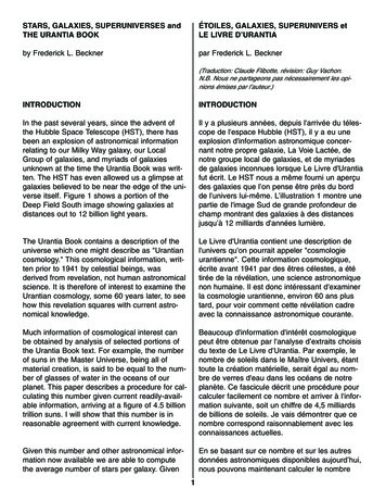
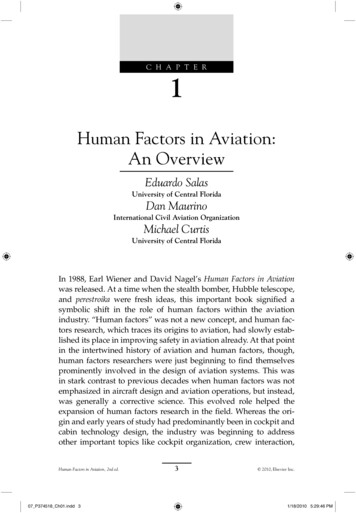
PROGRAM HISTORY AJTD MANAGErdENTA. RESPONSIBILITIESThe HST program is the result of a cooperative effort between NASA and theEuropean Space Agency, private contractors, and astronomers worldwide. Themanagement responsibilities included design, development, launch, and dailyoperations of the telescope. The NASA Centers and prime contractors involved inthe development of the HST, and their interrelationships, are listed in Figure 3-1.At NASA Headquarters, the director of the Astrophysics Division, who reportsto the NASA Associate Administrator for the Office of Space Science andApplications, has overall authority for the HST Project. He assigned the NASA HSTProgram Manager to ensure that NASA policies and Project goals are maintainedand to administer the schedule and budget. Overall science policy is theresponsibility of the HST Program Scientist.Marshall Space Flight Center (MSFC) was assigned as lead center for the HSTProject management and tasked with the development of the telescope flighthardware and the general checkout phase after deployment. Responsibility formeeting the technical performance goals and for managing the program withinbudget and schedule was also with MSFC. Figure 3-2 is the MSFC organizationchart for the HST.The other NASA Center with a major involvement in the Project is the GoddardSpace Flight Center (GSFC), which was responsible for verifying the performanceof the science instruments. GSFC also controls the daily operations of the HST.On October 16, 1990, the responsibility for the HST Project (except for the opticalsystem failure questions) was transferred from MSFC to GSFC.The two prime contractors for the Project were Lockheed Missiles and SpaceCompany, Inc. (LMSC) and the Perkin-Elmer Corporation (P-E). LMSC developedthe Support Systems Module (SSM) and supervised many subcontracts; P-Edesigned and developed the OTA, including the fabrication of the primary andsecondary mirrors. P-E was also responsible for verification testing and delivery ofthe OTA to LMSC, where the OTA was integrated with the other subsystems. Inaddition to the OTA, P-E developed the fine guidance sensors and wavefrontsensors used in the HST.
1NASAHEADQUARTERSSPACE FLIGHT'1HST SYSTEMSENGINEERING &INTEGRATION.tSSM DESIGN,FABRICATION,ASSEMBLY& VERIFICATIONFAINT OBJECTHST ASSEMBLY- HST MISSIONOPERATIONSPLANNINGI tSOLAR ARRAYHST/ORBITER/CREW INTERFACE& OPERATIONS,HST IN-FLIGHTMAINTENANCEPLANNING1 1SCIENCE OPERATIONS,CSCIENTIFICINSTRUMENTS (Sl)OTA DESIGN.FABRICATION,ASSEMBLY &VERIFICATIONSI C&DHSUBSYSTEMFGS SYSTEMENGINEERINGtSCIENCE &ENGINEERINGDATA ICATIONLAUNCHHST OPERATIONSCONTROL CENTER& UPERVISION OFSCIENCE OPERATIONSLSPACE FLIGHT& VERIFICATIONHST LAUNCH& ORBITVERIFICATIONACE TELESCOPEJOHNSONSPACECENTERMISSILES &SPACE CO.HST MISSIONOPERATIONSINFORMATION PROVIDED BY LOCKHEED MISSILES AND SPACE COMPANY, INC.Figure 3-1. Hubble Space Telescope responsibilities.
MARSHALLSPACE NANCE ANDREFURBISHMENTOFFICEMSFC RESPONSIBILITIESHST DEVELOPMENT LEAD CENTERTOTAL PROJECT MANAGEMENTOTA DEVELOPMENTSSM DEVELOPMENTHST INTEGRATION AND VERIFICATIONORBITAL VERIFICATION OPERATIONSMAINTENANCE AND REFURBISHMENTPLANNINGINFORMATION PROVIDED BY LOCKHEED MISSILES AND SPACE COMPANY, INC.Figure 3-2. MSFCtsHubble Space Telescope responsibilities.
Before P-E was selected as the OTA prime contractor, the company was askedto design and build a smaller hyperbolic mirror in order to demonstrate theirtechnical capability. A 1.5-rn mirror was successfully designed, fabricated, andtested using the new technologies that would be used for the larger 2.4-m HSTprimary mirror. After a competitive bid process, P-E was awarded the HSTcontract, based in part on their successful demonstration of the 1.5-m mirror andon other factors, including their proposed fine guidance sensors.Because NASA considered the quality of the primary mirror to be a majorchallenge, it directed P-E to subcontract with the Eastman Kodak Company tofabricate a second primary mirror. The fabrication and test methods used atEastrnan Kodak and P-E were entirely different. It was the responsibility of NASAto review the final specifications of the mirrors and to choose the best .one forflight. The P-E primary and secondary mirrors were selected.B. ENVIRONMENTDuring 1981 and continuing through early 1982, the HST program was beset bymany difficulties. The estimated cost of the P-E contract had increased several-foldand the schedule had slipped substantially. The fine guidance sensors werehaving serious technical problems, and the severity of the challenge to keep themirrors sufficiently free from contamination to meet the specifications in ultravioletlight was just being recognized. The program was threatened with cancellation,and management ability was questioned. All these factors appear to havecontributed to a situation where NASA and P-E management were likely to bedistracted from supervision of mirror fabrication.
A. HST OPTICAL DESIGNThe Optical Telescope Assembly in the Hubble Space Telescope is a twomirror reflecting telescope very similar to most Earth-based telescopes built in thelast 75 years. These two-mirror telescopes are generally referred to as Cassegraintelescopes, after the French cleric who first published the design. The OTA is aspecial type of Cassegrain telescope called a Ritchey-Chretien (R-C) that has betteroptical performance over a larger format in the image plane. The mirrors in theR-C are slightly more aspheric (have a greater departure from a pure sphericalshape) than in the Cassegrain type, but both types of telescopes are quitecommon. The primary mirror in the OTA, the one in which the error exists, is a2.4-m diameter concave hyperboloid. The 0.3-m diameter secondary mirror is aconvex hyperboloid. This makes the OTA a little less than half the size of theHale telescope on Mt. Palomar.B. OPTICAL TESTINGSpherical mirrors are easy to make and to test, but such mirrors do not producegood-quality images. The aspheric mirrors used in Cassegrain or R-C telescopescan produce theoretically perfect images, but their aspheric shape makes themdifficult to test. Because the two mirrors in the OTA are hyperboloids or asphericmirrors, special test optics are needed to guarantee that the mirrors are the correctshape. These special test optics, called null correctors, generate test referencewavefronts that make the aspheric mirror look spherical to the optician. The nullcorrectors achieve this effect by projecting an optical template of the desiredaspheric shape that can be designed to be accurate to better than 25 nanometers.C. NULL CORRECTORS AND OPTICSThe convex secondary mirror of the OTA was tested in a geometrically perfectnull test with what is called a Hindle Shell test, a modification of the classic HindleSphere test. Because hyperboloids have the property of perfectly imaging raysfrom one focus into the other focus, the Hindle Shell null corrector is used tophysically implement this test. The Hindle test of the OTA secondary was carriedout precisely as planned, 2nd the shape of this mirror met specification. The
aspheric shape of the secondary mirror was verdied through the use of twoindependent tests during fabrication of the component.In the manufacture of prior telescopes, refractive null correctors (RvNCs), suchas the one shown in Figure 4-1, were used. The combination of the two preciselymade and spaced lenses produces the desired optical template of the concaveaspheric mirror.Carrying out an unambiguous and accurate test to determine whether a nullcorrector is producing the correct optical template is a known difficulty. For theHST program, Perkin-Elmer concluded that an RvNC would not yield sufficientprecision for testing the figure of the primary mirror, and as a result, a new andnovel reflective null corrector (RNC) was designed. As shown in Figure 4-2, thePerkin-Elmer RNC consists of two spherical mirrors and one small field lens. (Themore common RNC design contains only a single mirror and a field lens.) In theP-E design, the shape of the optical template could be precisely predicted simplyby knowing the manufactured dimensions of the two mirrors and the lens,including the lens material, and the spacings of the three optical elements. PerkinElmer planned to certify the RNC with great care, and they did not plan to do anyindependent testing of the mirror.The RNC was designed to provide easy access to all the optical surfaces in thenull corrector in order to measure these spacings at any time. The spacingbetween the two spherical mirrors can be measured by determining the distancebetween the centers of curvature of the two mirrors. This measurement is doneinterferometrically, using a known metering rod of the desired length. In a similarmanner, the field lens spacing can be measured relative to the center of curvatureof the lower mirror. The spacings need to be correct to 10 pm to meetspecifications.This ability to measure the optical element spacings at any time is somethingthat is not possible with a traditional RvNC, made up of all lenses and no mirrors.The novel RNC that answered some of the misgivings about the RvNC approachwas one of the factors leading to the award of the HST contract to Perkin-Elmer.As a check on the position of the Coaxial Reference Interferometer (CORI)used with the RNC, an inverse null corrector (INC) was designed. When swungunder the RNC, the INC would simulate a perfect mirror, just as a perfect primarymirror would appear with straight fringes when viewed through the RNC(Figure 4-3).
POINT SOURCEOF LIGHTINOTE: THIS DRAWING NOT TO SCALEFigure 4-1.Two-element refractive null corrector.4-3
FIELD LENSiINOTE: THIS DRAWING NOT TO SCALEPRIMARYMIRRORIFigure 4-2. Reflective null corrector.
NULLCORRECTORPOSITIVE LENSI7INVERSENULLCORRECTORINEGATIVE LENSCONCAVE MlRRNOTE: THIS DRAWING NOT TO SCALEFigure 4-3. Inverse null corrector inserted below the reflective null corrector.
Although not considered as a backup or additional check of the opticaltemplate produced by the RNC, an RvNC was built to test the OTA primary duringearly stages of polishing and was again used to test the primary mirror during ameasurement of the vertex radius of curvature or "power" of the primary mirror.The RvNC had to be used for this radius measurement because the RNC had tohave central holes in the two mirrors (just as the primary had a hole) to let thelight through. Because of the holes in the RNC mirrors, it was not possible to seethe location of the vertex of the primary mirror."White-light" fringes were used as an initial setup procedure to align thereference test plate (i.e., the calibrated mirror inserted into the hole of the primarymirror) for the vertex radius measurement. This measurement was extremelysensitive to vibration, and the fringes could not be captured on film because of theshort duration and faintness of the images. Several observers were required towitness that the fringes were seen. When this test was accomplished, a heliumneon (He-Ne) laser replaced the white-light source in order to take photographs(interferograms) by which to make the vertex radius measurement.D. POLISHINGDuring the polishing of the OTA mirrors, the Hindle test was performed on thesecondary mirror, and its surface was polished until it looked like a pure sphere toabout 0.012-wave rms wavefront error at 632.8 nrn. This meant that the surfacewas the correct hyperboloid to this same quality, a quality better than thatspecified in the contract.The backup OTA primary mirror was polished at Eastrnan Kodak Companyusing both a refractive and a reflective null corrector of a completely differentdesign from the Perkin-Elmer version. This mirror matched the templates of thetwo null correctors to better than 0.014-wave rrns wavefront error at 632.8 nm, andthe Board has every reason to believe it is the correct hyperboloidal shape.The primary mirror now flying in the HST was polished using the Perkin-ElmerRNC as a guide or template. Again, the fit to the template was better than0.014-wave rms wavefront error at 632.8 nrn, better than the contract specificationfor the accuracy of the mirror. Unfortunately, as has been subsequently learned,there was an error in the template produced by the RNC, thus making the primarymirror the wrong shape.
E. FINAL TESTSA n end-to-end test of the OTA would have been very expensive to perform atthe level of accuracy specified for the telescope. The test would have cost on theorder of what the OTA itself cost, because a flat or plano mirror would have beenneeded. To test the flat mirror by a single interferogram would have required aspherical mirror about 15 percent larger than the flat mirror. Thus the test couldhave required two additional mirrors as large as or larger than the OTA primary.In hindsight, a much less severe test could have been done to check for a grosserror such as did occur. The belief at the time was that if the two mirrors hadeach exceeded their individual specifications, only a test at the level of accuracy ofthe individual mirrors would have been meaningful. Such a test would have beenvery hard to justify because of cost.Actually,
A. Final Test of the Primary Mirror D-1 B. Refractive Null Corrector Test of the Primary Mirror D-5 C. Inverse Null Corrector Fringes D-6 D. Secondary Mirror Test Interferogram D-11 APPENDIX E HST PERFORMANCE BASED ON AS-BUILT DATA E-1 Tables 2-1. HST scientific instrument specifications. 2-3 E-1. HST OTA paraxial design parameters. E-2