Transcription
2
3
″4
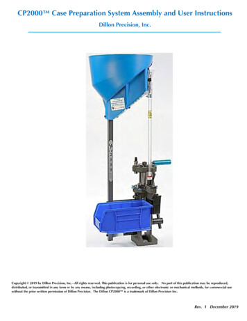
Casefeed Tube CasefeedMounting Post Operating Handle Die Storage Box—Parts installed onCP2000 Note:Seven LocatorButtons and Tabsshipped inside CP2000 Accessory Box Variable SpeedCasefeed system withLarge or SmallCasefeed plate CP2000 in the plasticbag with Large orSmall Swage System5
PowerSupply BoxCartridge BinBin Support BracketCartridge Bin BracketCP2000 Accessory BoxSpent Primer CupBag of HardwareCasefeed Post StudsIndex Ball and Spring(If No gScrews6
Tighten Set ScrewCut Tie whileholding theOperatingHandle down7
Hole forTightening5/16”Washer8
Note—Washer required hereNote--Cord Clamp9
Insert bottom ofCasefeed Tube intoCasefeed Adapterand then snap itinto the CasefeedTube Spring ClampLatch10
Power SocketCasefeed PlateDrive “Tee”Casefeed Plateengages PlateDrive “Tee”—sits flush onbottom of BowlSpent PrimerCupCollectionBin11Plug Adapterinto Socket
Alternate PrimerPocket Swage Station#8#1#7#66Case#1InsertStation#3 1#1#2#5#3Case picked upand insertedinto Shellplateby CasefeedPlungerStation 112#4AlternateTrimmer SizeStations 5 or 6—for availableDillon RapidTrim Motor andSize Trim Die
Deprime and SizeStation 2BackupRod/Support forSwaging ProcessStation 3--PistolStation 3--RifleBackup Expander tocontact inside bottomof case (web) whenOperating Handlereaches the bottom ofits stroke13
Station 5Alternate Trim Station 6Station 6--Alternate Trim StationAlternate Swage Station 7Station 7--Alternate Swage Station14
OpenEjectStation 8--Open/Eject15
Casefeed Plate Selection, Casefeed Window CuffPosition and Case Deflector Block Adjustment ChartThe chart below outlines the recommended Casefeed Plate and starting positionsfor the Casefeed Window opening position and Case Deflector Block position.Adjustment to the window position and Case Deflector may be necessarydependent upon the variation of your setup. The illustration at right shows theCasefeed Window opening positions from 1 to 6 as listed below. Start with theVariable Speed Control Knob at its mid position and adjust up or down to matchthe CP2000 cycle rate.CALIBERCASEFEED D D PLATEWINDOWPOSITIONDEFLECTORPOSITION.30 Luger, .30 MauserSMALL PISTOL#3DOWN.22 Remington JetLARGE PISTOL#3DOWN7.62x54LARGE RIFLE#1UP.32 ACP, 7.65MMSMALL PISTOL#3DOWN.218 BeeLARGE PISTOL#3DOWN.30 ARLARGE RIFLE#6DOWN.32 Short ColtSMALL PISTOL#3DOWN.220 SwiftLARGE RIFLE#3DOWN.30M1 CarbineSMALL RIFLE#6DOWN.32 S&WSMALL PISTOL#3DOWN.222 Remington MagnumSMALL RIFLE#3DOWN.300 BlackoutSMALL RIFLE#6DOWN.32 H&R MagnumSMALL PISTOL#3DOWN.22-250LARGE RIFLE#3DOWN.300 Wby./Win. Mag.MAGNUM RIFLE#1UP.327 Federal MagnumSMALL PISTOL#3DOWN.25-20 WinchesterSMALL PISTOL#3DOWN.300 WSM/RSAUMMAGNUM RIFLE#3UP7mm TCUSMALL PISTOL#3DOWN.223 Win./5.56x45mmSMALL RIFLE#3DOWN.300 Rem. Ultra Mag.MAGNUM RIFLE#1UP9mm, 9x21, .38 SuperSMALL PISTOL#3DOWN.223 WSSMLARGE RIFLE#3DOWN.300H&H/.308 Norma Mag.MAGNUM RIFLE#1UP9x18 MakarovSMALL PISTOL#3DOWN.224 Wby. Mag.SMALL RIFLE#3DOWN.32-20 WinchesterSMALL PISTOL#3DOWN9x25 DillonSMALL PISTOL#3DOWN.243 Win.,6mm Rem.LARGE RIFLE#3DOWN.303 BritishLARGE RIFLE#1UP.380 ACPSMALL PISTOL#3DOWN.243 WSSMLARGE RIFLE#4DOWN.30-30 WinchesterLARGE RIFLE#1UP.38 Super CompSMALL PISTOL#3DOWN.25-06, .257 RobertsLARGE RIFLE#3DOWN.308 Marlin ExpressLARGE RIFLE#1UP.38 Special,LARGE PISTOL#3DOWN.25 WSSMLARGE RIFLE#4DOWN.308 Win.LARGE RIFLE#1UP.357 MagnumLARGE PISTOL*#3DOWN.256 Win. Mag.LARGE PISTOL#3DOWN.30-06LARGE RIFLE#1UP.357 SIGLARGE PISTOL#3DOWN.257 Ack. Imp.LARGE RIFLE#3DOWN.30 T/CLARGE RIFLE#1UP10mmLARGE PISTOL#3DOWN.257 Wby. Mag.LARGE RIFLE#3DOWN.325 WSMMAGNUM RIFLE#4UP.40 S&WLARGE PISTOL#3DOWN6.5 CreedmoorLARGE RIFLE#5DOWN.338 Win., .340 Wby.MAGNUM RIFLE#1UP.41 Mag.LARGE PISTOL#3DOWN6.5 GrendelSMALL RIFLE#6DOWN.338 Rem. Ultra Mag.MAGNUM RIFLE#1UP.44 Special, .44 MagnumLARGE PISTOL#3DOWN6.5 Rem. Mag.LARGE RIFLE#3DOWN.350 Rem. Mag.LARGE RIFLE#1UP.45 ACPLARGE PISTOL#3DOWN6.5x55LARGE RIFLE#3DOWN8x57 MauserLARGE RIFLE#1UP.45 GAPLARGE PISTOL#3DOWN.264 Win. Mag.LARGE RIFLE#3DOWN.375 H&H Mag.MAGNUM RIFLE#1UP.45 Auto RimLARGE PISTOL#3DOWN6.8mm SPCSMALL RIFLE#6DOWN.375 Rem. Ultra Mag.MAGNUM RIFLE#1UP.45 Colt/S&W, .454 CasullLARGE PISTOL#3DOWN7mm TCUSMALL RIFLE#3DOWN.38-40 Win.LARGE PISTOL#3DOWN.45 Win. Mag.LARGE PISTOL#3DOWN.270 WinchesterLARGE RIFLE#1UP.444 MarlinLARGE RIFLE#1DOWN.460 S&WLARGE PISTOL#3DOWN.270 Wby. Mag.LARGE RIFLE#1UP.44-40 Win.LARGE PISTOL#3DOWN.475 Linebaugh, .480 RugerLARGE PISTOL#3DOWN7mm DakoaMAGNUM RIFLE#1UP.458 BushmasterLARGE RIFLE#6DOWN.500 S&W MagnumLARGE RIFLE#6DOWN7mm Rem./Wby. Mag.MAGNUM RIFLE#1UP.458 SOCOMLARGE RIFLE#6DOWN.50 AELARGE PISTOL#3DOWN7mm. Ult. Mag.MAGNUM RIFLE#1UP.458 Win. Mag.MAGNUM RIFLE#1UP.17 RemingtonSMALL RIFLE#3DOWN7mm Rem. SAUMMAGNUM RIFLE#1UP.45-70 GovernmentMAGNUM RIFLE#1DOWN.204 RugerSMALL RIFLE#3DOWN7MM STWMAGNUM RIFLE#1UP.221 Remington FireballSMALL RIFLE#3DOWN7mm WSM, .270 WSMMAGNUM RIFLE#1UP.22 HornetSMALL PISTOL#3DOWN7.62x39LARGE RIFLE#6DOWNITEMS WITH "*" REQUIRE THE SPACER WASHER (PART# 13703) BETWEEN THE CLUTCH AND PLATE16
AdjustmentNotchesKnurled NutAdjustmentScrewsDeflectorBlockClutchAssembly andAdjustmentScrewsSpacer Washer (3) goes on theunderside of Casefeed Plate17
Variable Speed ControlOn-Off SwitchDillon PN13804Dillon PN2043918
Dillon PN13733CaseLubeDentsCourtesy ofWestern Powder19
Loosen the 7/16” hex lock nut from the back ofthe frame--item 5 below. Turn item 4 the travelstop set screw with a ⅛” Allen Wrench at least 2full turns out.Raise the Operating Handle to its upper travellimit.Gently push back on the Handle and adjust the SetScrew CW until it contacts the Eccentric DriveHousing.Turn the Set Screw in one more turn and tightenthe 7/16” Lock Nut with 7/16” End Wrench.Verify the Shellplate indexes properly by verylightly holding pressure on the Shellplate withyour thumb while operating the Operating Handlefully up and down.If the Shellplate under indexes, back off the SetScrew stop ¼ of a turn CCW at a time untilindexing is correct.20Adjusting Set Screw-Stopposition and Lock Nut
Depriming BoltAssemblyDeprimingBolt LocknuttScrew Depriming BoltAssembly down until theshoulder of the depriming pinshoulder just touches the topof flash hole, then back it up 1½ turns.tPistol DeprimingAssembly—it isnon-adjustableand spring-loaded 21
Pistol Size Die justtouching Shellplateto 1/16 of a turn upfrom touching theShellplatePistolPistolBackupExpanderand LockNutPistolExpandingLinePistol22
Rifle Backup Expanderand Lock NutAdjust BackupExpander to contactinside bottom of casewhen the OperatingHandle reachesbottom of its strokeUniversal Die Body(Rifle)RifleTightenBackupExpanderLock Nutwith a casein placeBackup Expander tocontact inside bottomof case (web) whenOperating Handle justreaches the bottom ofits stroke⅛23
Turn the Swage Rodup (CCW) until the tipof the Swage Rodcontacts the inside ofthe primer pocketNote DesiredRadiusSwaged Primer PocketCrimped Primer PocketRifle BackupExpander andLock NutSmall and largereplaceableSwage Rod TipsPistol BackupExpanderand LockRingUniversal Dieand Lock Ring(Rifle)AdjustableSwage Rod,Adjusting Boltand Lock Nut24
AlternateSwagePosition 7TrimLengthLock nutInstall Die Lock Ringon the top or thebottom of theToolhead tomaximize theopening in the TrimDie Body for chipremovalNote: chipremovalopening issomewhatrestricted –putSize Lock Nuton bottom ofToolhead asshown to therightTypical case trimchips25
⅛Carbide cutter/insertwith 3 edgesTwo Piece ExhaustManifold—Connectto Shop VacuumExhaust Manifoldfasteners (2 each)26⅛
Exhaust ManifoldExhaust Port-Connect To ShopVacuumBackside of CP200027
ShellplateRifle Swage Backup RodCasefeed AdapterCasefeed PlungerReplaceable Swage TipSmall or LargeLocator Buttons and TabsReplaceCasefeedPlatePull Tubeout of SpringClip28
Torque to 20-25 ft-lbs.Alignment pin must align withhole in Shellplate and Framewithout bindingReplaceCasefeedPlunger29
⅛ Loosen the Boltattaching CasefeedEjector Tab androtate Ejector TabClockwise—to therightMake sure the Index Ball andSpring stay in position asshown and the Ball, Spring andhole are clean and free of anydebrisLoosen 4 Lock Ring InsertScrews, unthread and removeShellplate Lock Ring (5) andShellplate (6)Re-position Ejector Tab tojust clear the Shellplate 1/16” and re-tightenEjector Tab Screw30
31
One Dropof BlueLoctiteWrench Flats 7/16”No need to takeapart32
Re-install the Swage RodAssembly in CP2000Reinstall two Swager CoverPlates with four ScrewsReinstall the Clevis Pin andthe Spring ClipReinstall the Bearing Capand Screw Rifle Backup ExpanderAssembly Shown 33
No.1.CategoryCleanliness2.Casefeed IssuesIssueThe case prep process isinherently "dirty" due toresidue from used primers,leftover corn cobb fromtumbling, metal shavings fromtrimming and leftover caselube9mm cases may flip sidewaysin the Casefeed TubeCorrective Action1.Compressed air or a “can of air" and a 1” paintbrush are the reloader's “bestfriends.” At the end of a case prep session, blow out the Toolhead andShellplate areas.2.Periodically clean out the Size and Size/Trim Die with alcohol and swabs. Theywill get "gooey" over time.Cases are having trouble beinginserted into the ShellplateStation 1-- Cases havingtrouble entering the slot in theShellplate1. Tighten/minimize the clearance between the Shellplate, the Shellplate LockRing and the Frame. Test by pushing down on the edge of the Shellplate. Ifthere is excessive clearance (fells springy), tighten the Shellplate Lock Ring andsecure Lock Ring Insert screws.2.Verify there are no corn cobb particles in the Shellplate Pockets or underShellplate left over from cleaning the cases.3.Verify the correct Casefeed Adapter and Casefeed Plunger are being used4.Slow down the cycle rate.5.Damaged Shellplate. --Replace6. Dirty, wrong, worn or damaged Casefeed Plunger. --Clean and or replace.7.Check that the Shellplate is not over or under indexing.8.Wrong Shellplate.Casefeeder is on but CasefeedPlate doesn’t rotate1.Brass may be caught under the Casefeed Plate or in the Casefeed window.2.Casefeed Bowl is over full.3.Casefeed Plate is not fully seated on the Drive Motor Shaft.4.Bad Microswitch or Microswitch Lever caught on the inside of the Tube.5.The Clutch is slipping. --Adjust clutch per Casefeeder Instructions.Cases are falling upside down.1.Using the wrong Casefeed Plate for that caliber.2.Window Port Cuff is open too wide. See Casefeeder instructions.3.Casefeed is too full.4.CP2000 not secured properly or bench not stable.1.Check the angle of the switch lever and adjust as needed by gently bending it.Cases are hanging up on theMicroswitch Lever in theCasefeed FunnelThe case doesn’t drop intoCasefeed PlungerShellplate Indexing is “off’3.IndexingErratic /Incomplete IndexingShellplate over-traveling or“jumping backward” afterindexing1.Adjust the Casefeed Window as described in the Casefeeder Setup Section 8.1.2.Lower the speed of the Casefeed Motor.1.Wrong Casefeed Plunger or Casefeed Adapter2.Cases jammed in Casefeed Tube/Funnel.3.Tumbling media in Casefeed Tube.4.Case upside down, wrong caliber case mixed in.5.Casefeed Assembly is not adjusted properly.1.Clean and lubricate the Index Lever, Roller and Bolt. Readjust as specified inSection 8.4.2.Check Index Pawl tip for excessive wear. —Replace.1.Shellplate Lock Ring adjusted too tight. —Loosen up no more than 1/8 of a turn.2.Shellplate Lock Ring loosens when Shellplate turns. — Tighten Shellplate LockRing Insert screws3.Wrong size Locator Buttons.4.Index Pawl bent, worn, or Pawl Spring missing or broken—Replace.5.Index Ball and or Ball Index Spring missing or broken or dirty. — Clean and orreplace.6.Sticky material/debris under the Shellplate. --Remove the Shellplate, clean withsolvent and lightly lubricate Shellplate bore.7.Damaged or worn Shellplate. —Replace.8.Check Index Lever and Roller. —Remove Roller, Check Spring, Clean and tuberoller.9.Re-adjust Eccentric Drive Stop as described in Section 8.4 Page 201.Index Ball and Spring stuck down by “gunk” or debris. --Remove Shellplate andclean top of Frame and Index Ball, Spring and Shellplate.2.Not taking a full stroke on the Handle.3.Indexer Ring Pawl is worn or Index Stop needs adjusting4.Index Lever Return Spring damaged or missing.34
5.Index Block out of adjustment.Shellplate over/under indexesCrushing cases duringinsertion into Station 14.Sizing IssuesCase mouth hits the edge ofthe Size Die in Station 2damaging the caseDents in the case during sizingScratched CasesCase sticking in Size DieCase stuck in Size Die5.DeprimingFailure” PrimerPull Back”Station 2Primers at times may stick onthe end of the Depriming Pinand may be pulled back upinto the primer pocket. TheSwager Rod then crushes theprimer.Bending or breakingDepriming Pins6.ImproperSwaging andNeck Expandingin Station 3Case mouth hits the edge ofthe Expander/Backup Roddamaging the case in Station 3Swage Rod sticking in thePrimer PocketOver Swaging1.Adjust the Dillon Eccentric Drive Stop position locking Set Screw Stop on theback of the Frame. The upper travel limit for the drive has been factoryadjusted and should not require adjustment. This adjustment also controls theindexing of the Shellplate. If necessary adjust the travel limit screw asdescribed in section 8.41.Incomplete case insertion. Make a full stroke of the Operating Handle onevery cycle of the Handle.2.Not enough radius on Size Die entrance—Use Dillon Dies where available.3.Cycling Operating Handle too rapidly.1.Loosen the Die Lock Ring with a case in Station 2. Cycle the Handle all the waydown with the case in the Size Die and retighten the Die Lock Ring. This centersthe die in the Toolhead.1.Excessive Case lubrication during the resizing process can hydraulically formdents in the case. Disassemble and clean out the size die with a swab. Useenough lube on the cases to ensure they easily enter the sizing die. If the caseis resistant to going into the die, stop and re-lube. Without adequate lubricant,the case will stick in the die and the Shellplate can rip the rim off the case.2.This can also be caused by debris in the die.1.Brass residue will build up in the Size Die (even carbide) over extended periodsespecially if the brass cases are not cleaned well. This very hard brass residuewill leave vertical scratches on the case. Remove any hardened brass buildup inthe size die with Red 3M Scotch Brite wrapped around a wood mandrel. Chuckthe mandrel in a drill motor and run it gently back and forth inside the size dieto remove hardened brass buildup. Also, you can use Sweets 7.62 Solvent.2.Dirty Brass.3.New Brass has burrs. Tumble in corn cobb.1.Insufficient Lube on the case.2.Overpressure/” blown-out” case—out of spec/oversize.3.Alcohol from Dillon Case Lube not given time to evaporate.1.Remove die—remove stuck case—Re-lube cases with Dillon Case Lube.2.Use the stuck case removal feature in the Dillon Rifle Size Die. Some stuckcases may require the usage of a “Stuck Case Remover” available from RCBS.1.With rifle cases, place a deprimed case in station 2 with the Operating Handledown. Adjust the Rifle Depriming Bolt down until it stops on the inside of thecartridge flash hole and then back the Depriming Bolt up 1 and ½ turns and lockit in place.2.Depriming pin tip is damaged or bent—Replace.3.Polish the tip of the Depriming pin so the taper is gone. This gives a wider tipand the primer’s anvil is less likely to get jammed onto it.4.In the case of pistol depriming issues, make sure there are no burrs on the endof the Depriming Pin. Polish if necessary and make sure that the spring-loadedDepriming Assembly is intact, especially the “E” clip on top of the DeprimingBolt.1.Berdan case.2.Smaller case inside the larger case.3.Debris in case.4.Cycling Handle to fast—Case is still wiggling hitting the De-priming Pin.1.Slow down the cycling speed and smoothly operate the Handle. Check that theShellplate is not over or under indexing. Re-align Expander Rod with Case.1.Re-adjust the Swage Rod—See Section 8.5.5 for adjustment procedure1.Re-adjust the Swage Rod—See Section 8.5.5 for adjustment procedure35
Grease here—Roller, Bolt and Slot and CamGreaseSpringand Pin36
Oil –PinUse only 30 weight motoroil. DO NOT use apenetrating lubricant suchas WD-40, Breakfree, etc.GreaseGrease Zerk FittingLightly Grease bottom surface and Framewhere the Shellplate ID contacts the OD ofthe Frame37
Syringe grease the port in each“ear”—1 to 2 pumps every 25,000cyclesZerk fitting-Grease3-4 pumps—pump 12 times and cycleHandle every 25,000cycles —wipe offexcess greaseGrease bolt, roller and indexlever contact surfaceRemove, clean and greaseRoller (9), Bolt (8) and Pin (7)and reassemble38
Oil –ShaftCrankshaftBearingCrankshaftBearing2 SyringeGrease Ports39
SECTION 12.1/12.2/12.3 -CASEFEED BOWL, PLATE ANDCLUTCH ASSEMBLY ANDMOUNTING ASSEMBLYSECTION 13--OPTIONALDILLON RAPID TRIM 1500 CASETRIMMER AND SIZE/TRIM DIE—SECTION 12.4--CASE INSERTASSEMBLYSECTION 12.5/12.6--UPPERASSEMBLY, TOOLHEAD ANDSHELLPLATE ASSEMBLYSECTION 12.7--OPERATINGHANDLESECTION 12.8--SHELLPLATEINDEX ASSEMBLY (BACKSIDE)SECTION 12.9-- PRIMERPOCKET SWAGE ASSEMBLY--(2POSITIONS AVAILABLE)SECTION 12.10-- LowerAssembly—Dillon EccentricDrive -- ASSEMBLY, MAINSHAFT AND CRANKSHAFTSECTION 12.11—DILLONECCENTRIC DRIVE BEARINGASSEMBLYSECTION 15—MOUNTINGTEMPLATE40
41
42
43
44
45
ALTERNATEALTERNATESIZE ANDTRIMSTATIONS46
47
48
49
50
51
Short Trim Die Toolhead Setup ExampleStation 8Station 6Station 6-Forming andTrimming the.300 BlackoutCase in onepass-- .300Station 8 -Expanding theNeck -- .300Blackout NeckExpander (62372)and Locknut(12577) in aUniversal Die Body(17583) with a DieLock Ring (14067)Blackout Sizeand Trim Diewith RT 1500Case Trimmerand ExhaustManifold—(PartNo. above)Station 2Station 3Station 2-Depriming .223Case--.223 DeprimingStation 3-Swaging the PrimerPocket --.223 BackupBolt (13182), Locknut(12577) and DeprimingPin (13278)—withoutan Expander Ball in aUniversal Die Body(17583) with a Die LockRing (14067)expander (13332) andLocknut (12577) in aUniversal Die Body(17583) with a Die LockRing (14067)52Note—CP2000 ShortTrim Die Toolhead-complete (66026)
53
54
55
56
.41 Mag. LARGE PISTOL #3 DOWN 6.5 Grendel SMALL RIFLE #6 DOWN .338 Rem. Ultra Mag. MAGNUM RIFLE #1 UP.44 Special, .44 Magnum LARGE PISTOL #3 DOWN 6.5 Rem. Mag. LARGE RIFLE #3 DOWN .350 Rem. Mag. LARGE RIFLE #1 UP . hole are clean and free of any debris Loosen the Bolt attaching Casefeed Ejector Tab and rotate Ejector Tab

