Transcription
CS 294-7: Mobile Satellite SystemsProf. Randy H. KatzCS DivisionUniversity of California, BerkeleyBerkeley, CA 94720-1776 19961
Mobile Satellite Systems Like cellular systems, except that the basestations (i.e., satellites) move as will asmobile devices Satellite coverage attractive for areas of worldnot well served by existing terrestialinfrastructure: ocean areas, developingcountries2
Mobile Satellite Systems Interesting aspects of the satellite link:– 270 ms propagation delay (geosync)– Transmission cost independent of distance– Very high bit rates are possible; can avoid bandwidthlimitations of terrestrial links– An inherently broadcast medium– Dynamic assignment of channels between geographicallydispersed users– A transmitting station can receive its own transmission;can be exploited for transmission control3
Mobile Satellite Systems Assigned Frequencies–––––––––––P Band: 0.225-0.39 GHzJ Band: 0.35-0.53 GHzL Band: 0.39-1.55 GHzS Band: 1.55-5.2 GHzC Band: 3.9-6.2 GHzX Band: 5.2-10.9 GHzK Band: 10.9-36.0 GHzKu Band: 15.35-17.25 GHzQ Band: 36-46 GHzV Band: 46-56 GHzW Band: 56-100 GHzEarlier satellites, interferencewith terrestrial microwave links(4/6 GHz)Newer generation satellitesystems (14/16 GHz)Also interest in 20/30 GHzsystems (Ka Band, NASA ACTS) Antenna gain proportional to ƒ2, free space loss to 1/ƒ2 Counterbalanced by noise and absorption issues4
Equivalent Isotropic RadiatedPower (EIRP) Maximum power flux density at distance rfrom a transmitting antenna of gain G:– ΨΜ (G Ps) / (4 π r2)– An isotropic (omnidirectional) radiator would generatethis flux density EIRP is defined as G Ps– When expressed as dBW, Ps in W, G in dB:EIRP Ps G– e.g., transmit power of 6 W and antenna gain of 48.2 dB:EIRP 10 log 6 48.2 56 dBWEIRP InLossy LinkReceived PowerFree Space Loss: PR EIRP GR - 10 log (4 π r / λ)2 (dBW)5
Receiver Power EquationΨm EIRP/4πr2Effective Aperature of Receiver AntennaPR Ψm Aeffsurface areaof the sphere 4 π r2Aeff is proportionalityconstantIsotropicTransmitterGain measuresdirectionality ofreceiver antennaReceiver ΨmG Max Flux DenΨiIsotropic Flux DenAeff G λ2 / 4 π (antenna efficiency x aperature area)PR EIRP GR λ2 : EIRP GR - 10 log (4 π r / λ)2 in dB“Free Space Loss”4 π r2 4 π6
Free Space Loss FSL 10 log (4 π r / λ)2– in dBW , FSL 32.4 20 log r 20 log ƒ– e.g., ES to satellite is 42,000 km, ƒ is 6 GHz, what is FSL?» FSL 32.4 20 log 42000 20 log 6000 200.4 dB» Very large loss!!– e.g., EIRP 56 dBW, receive antenna gain 50 dB» PR 56 50 - 200.4 -94.4 dBW 355 pW Other sources of losses––––Feeder lossesAntenna misalignment lossesFixed atmospheric and ionospheric lossesEffects of rain PR EIRP GR - Losses, in dBW7
Noise Sources System Noise– Received power is very small, in picowatts– Thermal noise from random motion of electrons– Antenna noise: antenna losses sky noise (backgroundmicrowave radiation)– Amplifier noise temperature: energy absorptionmanifests itself as heat, thus generating thermal noise Carrier-to-Noise Ratio– C/N PR - PN in dB– PN k TN BN– C/N EIRP GR - LOSSES - k -TS - BNwhere k is Boltzman’s constant, TS is system noisetemperature, TN is equivalent noise temperature, BN isthe equivalent noise bandwidth– Carrier to noise power density (noise power per unit b/w):C/N0 EIRP G/T - Losses - k8
NoiseShannon’s Law: B BN log2 (PR / PN 1)Where B information-carrying capacity of the link (bits/unit bandwidth)BN usable bandwidth (hertz)PR/PN must not get too small!Noise power usually quoted in terms of noise temperature: PN k TN BNThe noise temperature of a noise source is that temperature that producesthe same noise power over the same frequency range: TN PN / k BNNoise density (noise per hertz of b/w): N0 PN / BN k TNCarrier-to-Noise: C/N0 PR / N0 PR / k TN : EIRP G/T - k - Losses in dBReceiver antenna figure of merit: increaseswith antenna diameter and frequency;More powerful xmit implies cheaper receiverSun, Moon, Earth, GalacticNoise, Cosmic Noise, SkyNoise, Atmospheric Noise,Man-made Noise9
Carrier-to-Noise RatioExample Calculation Example:– 12 GHz frequency,free space loss 206 dB,antenna pointing loss 1 dB,atmospheric absorption 2 dB– Receiver G/T 19.5 dB/K,receiver feeder loss 1 dB– EIRP 48 dBW Calculation:– C/N0 -206 - 1 - 2 19.5 - 1 48 228.6 86.1(Note that Boltzmann’s constant k 1.38 x 10⁻²³ J/K -228.6 dB)– Bottom-line: while the received signal is very small, thebackground noise sources are even smaller (but many othereffects increase the noise temperature, like rain absorption)10
Simplified Link Equation 10 log (C/N0) PS GS - FS L GR - TR - k - L dB where––––––––C/N0: ratio of signal pwr to noise pwr after being received (Hz)PS: RF pwr delivered to transmitting antenna (dBW)GS: Gain of the transmitting antenna relative to isotropic rad (dBi)FSL: Free space loss (dB)GR: Gain of the receiving antenna (dBi)TR: Composite noise temperature of the receiver (dBK)k: Boltzmann’s constant (-288.6 dBW/K-Hz)L: Composite of propagation loss (dB) G 10 log (η π2 D2/λ2) dBi– η: antenna efficiency, D: diameter FSL 10 log [(4 π r)2/λ2] dBPath loss and antennagain increase with squareof radio frequency– r is distance11
Frequency vs. Losses vs. BER Higher transmission frequency has the advantage ofrequiring a smaller receiver antenna BUT suffers from higher attenuation losses throughatmosphere To achieve the same C/N0 performance, which isrelated to BER, actually needs a LARGER antennathan same transmission power at a lower frequency But still frequency allocation advantages for highfrequencies Solution is to use higher transmitter power at thesatellite and earth station for the higher frequencytransmissions12
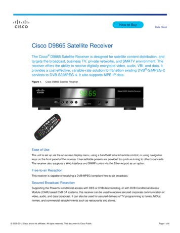
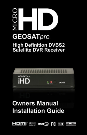
Atmospheric Attenuation50Decreasing angle of elevation% of signalpower lossloss in3.0dBAbsorption byHeavy Rain2.54-6 GHz402.0Absorption byThick Fog1.5301.02010AtmosphericAbsorption5 10 20 30 40 Elevation of Satellite0.550 13
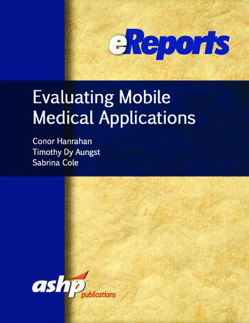
Atmospheric Attenuation99.9Decreasing angle of elevation% of signalpower lossloss in30dBAbsorption byHeavy Rain12-14 GHz9920Absorption byThick Fog1590302510AtmosphericAbsorption5 10 20 30 40 Elevation of Satellite550 14
Atmospheric Absorption Contributing Factors:–––––Molecular oxygenUncondensed water vaporRainFog and cloudsSnow and hailConstantDepend onweather Effects are frequency dependent– Molecular oxygen absorption peaks at 60 GHz– Water molecules peak at 21 GHz Decreasing elevation angle will also increaseabsorption loss15
Atmospheric AbsorptionLocationSat Ant PointingLoss, dBRain Attenuation, dB Atmos Absorp 1/4 Canada 1/2 Canada0.1% dB, Summer0.5%1%Coverage 20.30.41% of the time, rain attenuation exceeds 0.3 dB(99% of the time, it is less than or equal to 0.3 dB)0.5% of the time, it exceeds 0.5 dB0.1% of the time, it exceeds 1.9 dB16
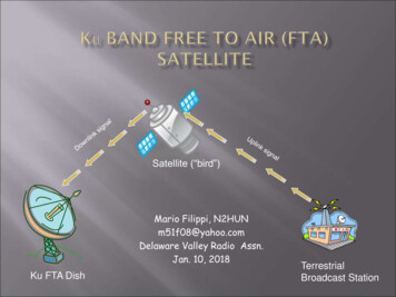
Antenna Temperature1000Galaxy Noise100Galactic NoiseRegionTemp (K)Low NoiseRegionTropospheric NoiseRegion5 deg elev10Rain addsnoise as wellas attenuation90 deg elev10.11.0Freq (GHz)10.0100.017
Rain and Signal Losses Rain Effect– Rainfall introduces attenuation by absorption and scattering ofsignal energy– Absorptive attenuation introduces noise» A dB rain attenuation yields power loss ratio of 10A/10» Effective noise temperature of rain TRain TA (1 - 1/A)» TA is a measured quantity between 270 and 290 K– Suppose “clear sky” C/N is 20 dB, effective noise temperature is400 K, apparent absorber temperature is 280 K, rain attenuationexceeds 1.9 dB 0.1% of time, how does this effect C/N?» 1.9 dB 1.55:1 power loss (i.e., 101.9/10 1.55)» Train 280(1-1/1.55) 99.2 K» 400 99.2 499.2 Kchange in noise power is 499.2 - 400 0.96 dB( 10 log (499.2/400))» C/N 20 - 1.9 - 0.96 17.14 dB18
Transmission Losses Up-Link (Geosync)– Up-link ƒ 6.175 GHz, D 36,000 km– Path loss is a function of frequency and distance minustransmitter and receiver antenna gain– Loss 132.7 - 20 log dt - 20 log drdt transmitter antenna: 30 mdr satellite receiver antenna: 1.5 m– Loss 132.7 - 29.5 - 3.5 94.7 dBTransmitted pwr/received pwr 2.95 x 10⁹ Down-Link– Down-link ƒ 3.95 GHz– Footprint of antenna affects its gain; wide area footprintyields a lower gain, narrow footprint a higher gain– Loss 136.6 - 20 log dt - 20 log drLoss 136.6 - 3.5 - 29.5 103.6 dB19
Downlink Footprintπ x 39622 square miles (full earth coverage)G 4π 240002 147 22 dBπ 39622π x 15002 square miles (CONUS coverage)G 4π 240002 1024 30 dBπ 15002Greater directionality implies antenna larger size or increased frequency4 x antenna covering area 1/4 of size yields gain 16 x as great (12 dB)20
Downlink Footprint36 MHz transponder:One color TV channel OR1200 voice channels OR50 Mbps data rateAntenna is beam formed toprovide specific coverage areasSpot beams: high power, narrow beamStrong signal to supportsmaller antennas vs. worse weatherWeaker signal requires larger antennas21
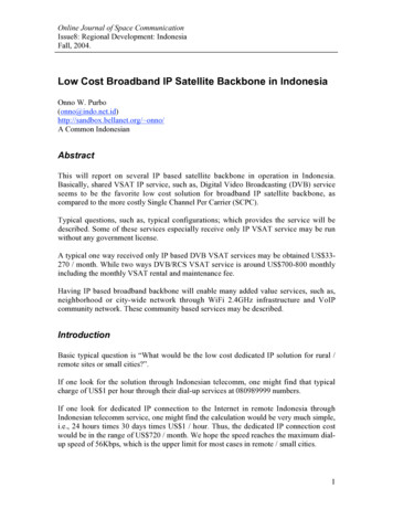
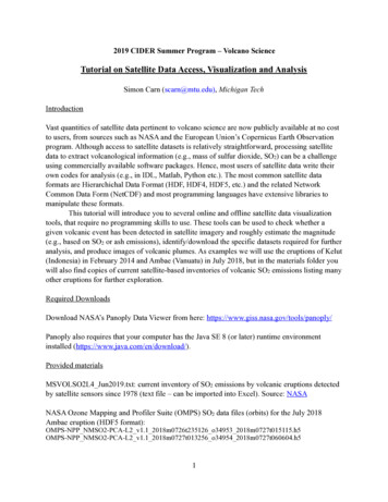
Typical LossesFrontend Gain: 14 dBAntenna GainSpot: 29 dBGlobal: 17 dBTransponder output: 8 dBWAntenna GainSpot: 26 dBGlobal: 14 dBEIRPSpot: 34 dBWGlobal: 22 dBWFree space loss:200 dBAttenuation in rain& cloud: 2 dB6 GHzFree space loss:196 dBEIRP: 105 dBWAntenna Gain: 62 dBXmit output: 43 dBWAntenna Gain: 59 dBReceived SignalSpot: -103 dBWGlobal: -115 dBW4 GHz4-6 GHz system22
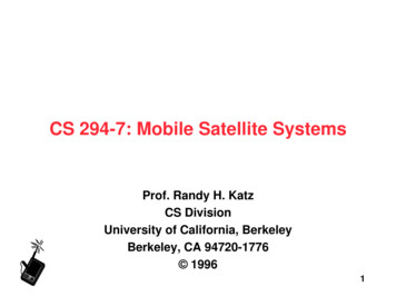
-1610-18Atmos LossLoss due to bad rainstorm(worse losses at 20/30 GHz)Output SignalPower AmpLow Noise AmpSat Ant GainSat AmplificationES Rcv Ant GainSat-Earth Path LossAtmos LossSat Ant GainEarth-Sat Path LossXmit LossES Xmit Ant GainES AmplifiersInput SignalTypical Losses (4/6 0-18023
Satellite Link Summary: Up-Link4/6 GHz 12/14 GHz 20/30 GHz 12/14 GHz35252020Transmitter power, dBw-1-1-1-1Transmitter system loss, dB55467662Transmitter antenna gain, dB0-0.5-2-0.5Atmospheric loss, dB-200-208-214-208Free space loss, dB20465360Receiver antenna gain, dB-1-1-1-1Receiver system loss, dB-92-93.5-69-68.5Received power, dBw1000100010001000Noise temperature, K363635036Received b/w, MHz-128-128-118-128Noise, dBw3634.54959.5Received SNR, dB2102510Loss in bad storm, dB3424.52449.5Received SNR in bad storm, dBDBS, receive-only ES1.8 m, 9 m satellite antenna24
Satellite Link Summary: Down-Link4/6 GHz 12/14 GHz 20/30 GHz 12/14 GHz1820810Transmitter power, dBw-1-1-1-1Transmitter system loss, dB16444958Transmitter antenna gain, dB-197-206-210-206Atmospheric loss, dB0-0.6-2-0.6Free space loss, dB51447244Receiver antenna gain, dB-1-1-1-1Receiver system loss, dB-114-100.6-85-96.6Received power, dBw25010002501000Noise temperature, K363635036Received b/w, MHz-131-128-121-128Noise, dBw1727.43631.4Received SNR, dB2102510Loss in bad storm, dB1517.41121.4Received SNR in bad storm, dBDBS, receive-only ES1.8 m, 9 m satellite antenna25
Satellite Path Diversity forImproved Service Availability Two alternatives:– Single path, “medium power”(16-17 dB link margin)» Still mostly line of sightservice» Handoff will improveservice availability but onlyif more satellites in view– Multiple path, “low power” (7-8dB link margin)» Substantial improvementsin service availability» Handoff further improvesservice availability» Works with any orbit26
DBS SystemsBandDownlink freq alloc, GHzUplink freq alloc, GHzPrimary UseSecondary UseTerrestrial InterferenceSatellite SpacingDetermined bySatellite InterferenceSatellite EIRP, dBWHigh PowerKu12.2-12.717.3-17.8DBSPt-to-PtNo9 degITUNo51-60Medium PowerKu11.7-12.214-14.5Pt-to-PtDBSNo2 degFCCYes40-48Low PowerC3.7-4.25.925-6.425Pt-to-PtDBSYes2-3 degFCCYes33-37Ku band: less utilized; not used in land-based microwave systems,60 cm dishes (vs. 3 m C-band dishes)27
DBS SystemsHigh PowerParameter12.2-12.7Downlink Band, GHzFull/HalfSatellite Coverage100-260Transponder pwr, W51-58Transponder EIRP, dBWRHC/LHCPolarization*8-16Typ Transponders per Sat24Transponder b/w, MHz0.3-0.8Home Antenna Diam, m100-200Receiver Noise Temp, K400-800Cost, US Medium 6100-200600-1200Low Power3.7-4.2Full CONUS5-1033-37H/V24362.5-4.835-802000-4000* RHC: right hand circular, LHC: left hand circular,H: horizontal, V: vertical28
Global Positioning System 24 satellites, near circular inclined orbits (20,000 km)– 4 satellites yield lat, long, altitude– L band transmission: 1575.42 MHz/1227.6 MHz– Foot nav error 10-9 s timing error Receiver must measure time, from which prop delayand range to satellites in view can be determined Satellites broadcast their ephemeris (orbitalelements) and the current time in UTCContinuoussignal modulatedby clock signalsatomicclockson-board4th satelliterequired toresolve timeshiftsKnown pointsin coordinatesystemdistanceClock offset represents prop delay x,y,z,time 4 eq, 4 unk29
OrbitsInclinedEllipiticalOrbitsCircular Orbit30
OrbitsLow Earth OrbitsHeight: 100-300 milesRotation Period: approx. 90 min.Time in LOS ofearth station: 15 min.Medium Earth OrbitsHeight: 6000-12000 milesRotation Period: 5-12 hrs.Time in LOS ofearth station: 2-4 hrs.Geosync OrbitsHeight: 22,282 milesRotation Period: 24 hrs.Time in LOS ofearth station: 24 hrs.31
Satellite res ES gatewaywithin sight of every satelliteIntersatellite linkscan reduce the need forES gateway coverage32
Advantages/Disadvantageswith GeoSync Advantages:–––––Since stationary, requires no ground station trackingNo inter-satellite handoff, permanently in view42.4% of earth surface in view of one satelliteThree satellites give full earth coverageAlmost no Doppler shift, yields reduced complexity receivers Disadvantages:– 35786 km orbits imply long transmission latencies, on order of250 ms for one-way, 500 ms round trip– Weak received signal (varies with inverse of square of distance)– Does not provide good coverage at high latitudes (80 degrees) orurban areas at medium latitudes (40 degrees)33
Low Earth OrbitAdvantages/Disadvantages Advantages:– Reduced launch costs to place in low Earth orbit (e.g., airplane/booster launched)– Much reduced pass loss, implies lower cost satellite ( 0.5-2M)– Much shorter transmission delays Disadvantages:– Short visibility from any point on earth demands potentially largeconstellations (e.g., 15 minutes, with small earth footprint)– Satellite lifetime dramatically reduced when in low orbit(e.g., 1-3 months at 300 km orbit)– Radiation effects reduce solar cells and electronics lifetimes» Van Allen radiation belts limit orbit placement» Belt 1: 1500-5000 km» Belt 2: 13000-20000 km34
High Altitude Long EndurancePlatform: Compromise System25-800 km“Space Plane”or LEO35,870 km35
Orbital ConsiderationsLEOMEOGEOVan Allen RadiationEclipse IntervalSignal Time DelaysSpacecraft ElevAngleSpace JunkLow level radiationFrequent day-night cycling20 ms for 2-way commRapidly varying,frequently near horizonMajor problem at this orbitModerate level radiationInfreq day-night cycling100 ms for 2-way commSlowly varying,infrequently near horizonSmall # at this orbitLow level radiationInfreq day-night cycling250 ms for 2-way commNo variation, near horizononly at high latitudesModerate at this orbit# Sats RequiresCost Sat LaunchSat LifetimeLarge #, 30-60Low costShort, 5 yearsModerate #, 10-20Moderate costLong, 10-15 yearsSmall #, 3-6High costLong, 10-15 yearsHandoffs/CrosslinkCost of Ground SegCost Pers CommsIncremental CoverageFrequent HOComplex and costlyModerate cost, hi weightNot practicalNo HOs/crosslinksLow costModerate cost/weightPracticalNo HOs/crosslinksLow costInexpensive but heavyVery Practical36
Comparing the OptionsSystem TypeSys CostGEO: 3 satellites 1.2B8 Beams/7 Year LifeMEO: 12 satellites 2B20 Beams/5 Year LifeLEO: 50 satellites 4B40 Beams/5 Year LifeMega LEO: 800 satellites 12B50 Beams/5 Year LifeHALE: 12 Cells 10 M10 Year LifeTerrestrial 50 M30 Cells/20 Year LifeCoverage Beam Thruput Perf Index12.6 x 106 km2200 Mb 2834 permb/km2/yr250 Mb 6451 per3.1 x 106 km2mb/km2/yr50 Mb 8680 per1.5 x 106 km2mb/km2/yr100 Mb 6000 per1.5 x 106 km2mb/km2/yr200 Mb0.18 x 106 km2 1852 permb/km2/yr90 Mb 82,000 per0.008 x 106 km2mb/km2/yrIndex System Cost/ (Thruput * Beam Size * # Sat * Beams * Life * Eff)e.g., for LEO, MEO, eff .3 since 70% of time sat at high lat or over oceanCosts do not include earth station, which is much higher for GEO37
Mobile Satellite Systems Geostationary Systems– INMARSAT ( 15,000 telephone, 5.50/min)– MSAT ( 2000 telephone, 1.45/min) Big “LEO” Systems––––ARIESELLIPSOIRIDIUMODYSSEY Little “LEO” Systems––––OrbcommLEOSATSTARNETVITASAT38
IRIDIUM Motorola Voice (4.8 kbps), Data (2.4 kbps), Fax, LocationServices 66 satellites in 6 polar orbits (780 km) 48 spot beams per satellite forming “cells”230 simultaneous duplex conversations Satellite-to-satellite links as well as to ground(Ka band@20 GHz to gateways & crosslinks,L band at 1.5GHz to handhelds) FDMA uplink, TDM downlink Supports satellite handoff during calls39
ICO Global Communications Funded by Inmarsat, Hughes to build the satellites ICO Intermediate Circular Orbit (8-10,000 km)––––6-20 satellites to cover earth, vs. 40-70 for LEO and 3-6 for GEO200 ms propagation delayHigh average elevation angle from user to satellite ( 40 degrees)High probability of visibility from more than one satellite, yieldspath diversity (70% of each footprint overlaps with anothersatellite)– Relatively slow moving satellites (1 degree per minute)– Minimum requirements for establishing a connection:» ES can see satellite 5 degrees above horizon» User can see satellite 10 degrees above horizon– TDMA, 4500 (750 carrier waves) telephone channels per satellite40
ICO-NetSAN: SatelliteAccess NodeSatellite GW Global RoamingES VLRES VLRES VLRES VLRES VLRSharedHLRES VLRES VLRES VLRES VLRPSTNPSDNPLMNGWES VLRES VLRES VLRInterSANNetwork41
ODYSSEY TRW Voice, Data (9.6 kbps), Fax, Location Services 12 satellites, 4 in each of 3 orbital planes3000 voice circuits per satellite Medium earth orbit: 10370 km CDMA access techniques No handover between satellites, because oflong satellite visibility from ground Steering antenna scheme also eliminatesneed for spot beam handovers42
GLOBALSTAR Loral, QualcommVoice, Data (9.6 kbps), Fax, Location Services48 satellites (8 spares), inclined orbits, 1400 kmNo satellite handovers, elliptical spot beams (6 persat) insure long coverage of mobile user CDMA access techniques ARIES, similar proposal from Consellation ELLIPSO, 15 satellites in elliptical orbit (reach apogeeover mid latitudes of northern hemisphere ) plus 9 inequalitorial circular orbits to cover rest of the world43
Teledesic Major Investors: Bill Gates. Craig McCaw 21 orbital planes, 40 satellites per plane, 840satellites total(!!)— 9 billion to deploy 700 km, circular orbits, high elevations 20 Ghz Ka band, large number of satellitesmitigates rain attenuation problems Hand held communicators can see two satellites atall times: soft handoff, load sharing Voice/Data up to 2 Mbps44
Teledesic Unique flower-shaped satellite with sophisticatedphase array antennas45
Mobile Satellite SystemsSYSTEMINMARSAT MMApplicantComsat, llipsatCorp.Orbital SciencesSystem TypeGeosatelliteGeosatelliteMeosatelliteBig LeoSatBig Leo SatBig LeoSatBig Leo SatLittle Leo SatPurposeVoice, DataVoice, DataVoice, DataVoiceVoiceVendors,PartnersMagnavox, etc.Hughes,TelesatTRWMotorola,etc.RBOCs,PTTsType ofPortableFormfactorFixed InfrastructureNeededComm elephonePocketTelephoneHandheld alGeographicCoverageWorldwideN. AmericaWorldwideWorldwideWorldwideWorldwideData, PagingConstellCommsHarris,FairchildChampion, etc.46
Mobile Satellite SystemsSYSTEMINMARSAT esYesYesPSTN AccessYesYesYesYesYesvia PDNs# of Satellites429 to 126648486, then 2426Orb Alt (km)36,00036,00010,37078014141020580/7800765Orb Type/Locs18,55W;63W, 139W62W, 139WLaunch Date1980s199519981996Service Date19881996199919981997Freq OORBCOMMElliptical19961997L-BandL-BandUHF, VHF47
Mobile Satellite SystemsSYSTEMINMARSAT MMFrequencies1.6 GHz1.6-1.7 GHz1.6, 2.4 GHz1.6, 2.4GHz1.6, 2.4 GHz1.6, 2.4GHz1.6, 2.4GHz137, 149,400 CDMACDMALatency(2-way)500 ms (rt)500 ms (rt) 120 ms (rt) 10 ms (rt) 10 ms (rt)Price(Handheld) 20-30,000 2-4,000 250-450 2002000 700-1000 1500 600 50-350Price(Airtime) 5.50/min 1.50/min 0.65/min 3.00/min 0.30/min 30.00/month 0.50/min 50.00/month 10 ms (rt)48
System SummaryService TypeOdysseyICOVoice, data, fax,Voice, data, fax,paging, messaging paging, messaging,pos location4.84.8GlobalstarVoice, data, fax,paging, videoConstellationVoice, data, fax4.8Data (kbps)9.62.4Adaptive2.4/4.8/9.67.2System cost 1.8B 2.6B 2.0B 1.7BUser terminal cost 300“Several Hundred” 750N/A10 years10 years7.5 yearsN/ACall rates (per min) 0.65 1.00-2.00 0.35-0.55N/AOps scheduled200020001998199812 3 spares10 2 spares48 8 spares36CDMATDMACDMACDMAVoice (kbps)Satellite Lifetime# of SatellitesMultiaccess methodInvestorsTRW, TeleglobeINMARSAT, Hughes Loral-Qualcomm,AirTouch, Vodafone,SpaceDeutche Aerospace,Dacom2.4OrbitalSciences,Teleglobe49
System SummaryService TypeIridiumVoice, data, fax,paging, videoTeledesicVoice, data, fax,paging,Voice (kbps)2.4/4.816.0EllipsoVoice, data, fax,paging, video, poslocation4.2Data (kbps)2.416.0-2048.00.3-9.6System cost 3.7B 9.0B 750M 2500-3000N/A 10005 years10 years5 yearsCall rates (per min) 3.00N/A0.50Ops scheduled19982002199866 6 spares840 84 spares10 6 sparesUser terminal costSatellite Lifetime# of SatellitesMultiaccess methodInvestorsFDMA, TDMA,TDMA, SDMA,TDDFDMA, ATDMAMotorola,Gates, McCawRaytheon, GreatWall Ind, KhrunichevEntr., Kyocera, Mitsui,Mawadi GroupCDMAWestinghouse,Harris, IsraeliAircraft Ind.50
Free space loss: 200 dB 4-6 GHz system Antenna Gain Spot: 29 dB Global: 17 dB Antenna Gain Spot: 26 dB Global: 14 dB Free space loss: 196 dB Antenna Gain: 59 dB Received Signal Spot: -103 dBW Global: -115 dBW EIRP Spot: 34 dBW Global: 22 dBW Frontend Gain: 14 dB Transponder output: 8 dBW 6 GHz 4 GHz. 23 Typical Losses (4/6 GHz) 1 102 104 106 .