Transcription
www.mercury-security.com2355 MIRA MAR AVE. LONG BEACH, CA 90815-1755, (562)986-9105 FAX (562) 986-9205This device complies with part 15 of the FCC Rules.Operation is subject to the following two conditions: (1) Thisdevice may not cause harmful interference, and (2) thisdevice must accept any interference received, includinginterference that may cause undesired operation.EP1501 Intelligent Controllerwith Paired Reader Interface for One Physical BarrierInstallation and Specifications:1.General:The EP1501 intelligent controller provides decision making, event reporting and database storage for theMercury hardware platform. Two reader interfaces configured as paired or alternate readers providecontrol for one physical barrier.Host communication is via the on-board 10-BaseT/100Base-TX Ethernet port.Note: For UL compliance, the Power Sourcing Equipment (PSE) such as a PoE enabled network switchand/or PoE power injectors must be UL Listed under UL294B.Reader port 1 can accommodate a reader that utilizes TTL (D1/D0, Clock/Data), F/2F, or 2-wire RS-485device signaling, also provides tri-state LED control, and buzzer control (one wire LED mode only). Thisport can also utilize multiple 2-wire RS-485 multi-dropped devices, such as up to two readers or up toeight remote serial I/O devices.Reader port 2 can accommodate a reader that utilizes TTL (D1/D0, Clock/Data), or F/2F signaling, alsoprovides tri-state LED control, and buzzer control (one wire LED mode only). Two Form-C contact relayoutputs may be used for door strike control or alarm signaling. The relay contacts are rated at 2 A @ 30Vdc, dry contact configuration. Two inputs are provided that may be used for monitoring the doorcontact, exit push button or alarm contact. Input circuits can be configured as unsupervised orsupervised. The EP1501 requires Power over Ethernet (PoE) or 12 Vdc for power. The EP1501 may bemounted in a 3-gang switch box; a mounting plate is supplied with the unit, or may be mounted in anenclosure; the supplied mounting plate has mounting holes that match the MR50 mounting footprint.2.EP1501 Hardware:PoE/12VdcPOWER SELECTORJUMPER (J3)5.40 [137.16].15 [3.81]2.55 [64.77]112.55 [64.77]1TB1TB1TB2TB312VJ31.15 [3.81].20 64322.75 [69.85]14 3 2 1J5S1S2ONRESET SWITCH5J6BT1Ø .125 [Ø3.175]6 PL2.35 [59.69]K1J4ETHERNETCONNECTOR(J6)J1DIP SWITCHESSTATUS LEDs CHASSIS GND.20 [5.08]RELAY K2 LEDRELAY K1 LEDSOLDER SIDEMercury Security 2014EP1501DOC 10107-0036REV 1.07Page 1
3.EP1501 Wiring and Setup:EP1501 RCLKDATGNDLEDBZRCLKDATInput 6VOGNDVINGNDNO1-CNCNO2-CNCAuxiliary Power Output – 12 VdcAuxiliary Power Output GroundInput Power – 12 Vdc (from local power supply)Input Power GroundRelay K1 – Normally Open ContactRelay K1 – Common ContactRelay K1 – Normally Closed ContactRelay K2 – Normally Open ContactRelay K2 – Common ContactRelay K2 – Normally Closed ContactInput 2Reader 1 Power Output – 12 VdcReader 1 LED OutputReader 1 Buzzer OutputReader 1 CLK/Data 1/TR Reader 1 DAT/Data 0/TRReader 1 GroundReader 2 LED OutputReader 2 Buzzer OutputReader 2 CLK/Data 1 InputReader 2 DAT/Data 0 InputJumpers:JUMPERS SET ATJ1J2J3J4J5J6J7Mercury Security 2014DESCRIPTIONN/AN/APoEFactory Use OnlyFactory Use OnlyEP1501 powered from the Ethernet connection12VEP1501 powered from an local 12 Vdc power sourceconnected to TB4-3 (VIN), TB4-4 (GND)N/AN/AN/AFactory Use OnlyFactory Use Only10-Base-T/100Base-TX Ethernet ConnectionCabinet Tamper Switch Input: short tamper secureEP1501DOC 10107-0036REV 1.07Page 2
DIP Switches:The four switches on S1 DIP switch configure the operating mode of the EP1501 processor. DIPswitches are read on power-up except where noted. Pressing switch S2 causes the EP1501 to rmal operating mode.After initialization, enable default User Name (admin) andPassword (password). The switch is read on the fly, no need to reboot. See IT Security section for additional information.Use factory default communication parameters.ONONXOFFXXONXUse OEM default communication parameters. Contact systemmanufacture for details. See Bulk Erase section below.Disable TLS secure link. Switch is read only when logging on.All other switch settings are unassigned and reserved for future use.Factory Default Communication Parameters:Network: static IP address: 192.168.0.251Subnet Mask: 255.255.0.0Default Gateway: 192.168.0.1DNS Sever: 192.168.0.1Host port: IP server, no encryption, port 3001, communication address: 04.Bulk Erase Configuration Memory:The bulk erase function can be used for the following purposes: Erase all configuration and cardholder database (sanitize board) Update OEM default parameters after OEM code has been changed Recover from database corruption causing EP1501 board to continuously rebootIf clearing the memory does not correct the initialization problem, contact technical support.Bulk Erase Steps: Do not remove power during steps 1-8.1. Set S1 DIP switches to: 1 & 2 "ON", 3 & 4 "OFF".2. Apply power to the EP1501 board.3. Watch for LEDs 1 & 2 and 3 & 4 to alternately flash at a 0.5 second rate.4. Within 10 seconds of powering up, change switches 1 or 2 to "OFF". If these switches are notchanged, the EP1501 board will power up using the OEM default communication parameters.5. LED 2 will flash indicating that the configuration memory is being erased.6. Full memory erase takes up to 60 seconds.7. When complete, only LEDs 1 & 4 will flash for 8 seconds.8. The EP1501 board will reboot 8 seconds after LEDs 1 & 4 stop flashing (no LEDs are on during thistime).5.Input Power:The EP1501 is powered by one of two ways (jumper selected, J3): Power is supplied via the Ethernet connection using PoE, fully compliant to IEEE 802.3af Or local 12 Vdc power supply, TB4-3 (VIN), TB4-4 (GND)6.Communication Wiring:The EP1501 controller communicates to the host via the on-board 10-BaseT/100Base-TX Ethernetinterface.Mercury Security 2014EP1501DOC 10107-0036REV 1.07Page 3
7.Reader/Serial I/O Device Wiring:Reader port 1 supports TTL (D1/D0, Clock/Data), F/2F, or 2-wire RS-485 device(s). Reader port 2supports TTL (D1/D0, Clock/Data), or F/2F. Power to reader port 1 is 12 Vdc at 180 mA maximum. Thereader connected to reader port 2 may be powered from the 12 Vdc auxiliary power supply output; TB4-1and TB4-2. Readers that require different voltage or have high current requirements should be poweredseparately. Refer to the reader manufacture specifications for cabling requirements. In the 2-wire LEDmode, the buzzer output is used to drive the second LED. Reader port configuration is set via the hostsoftware.Reader port 1 can support up to eight 2-wire RS-485 remote serial I/O devices using MSP1 protocol or upto two OSDP devices. If two OSDP devices are used, reader port 2 will not support a third reader. If onlyone OSDP device is configured, then reader port 2 is available for a second reader. The maximum cablelength is 2000 ft. (610 m). Do not terminate any RS-485 devices connected to reader port 1.When powering remote device(s) from the EP1501, be cautious not to exceed the maximum current limit.Cable gauge must also be evaluated. See specifications section for details.Reader Wiring Diagrams:SECOND READER PORTFIRST READER PORT1TB2LEDBZRCLK/D1DAT/D0TB4VOGNDVINGNDReader Port 1Typical D1/D0 or Clock/Data ReaderReader Port 2Typical D1/D0 or Clock/Data ReaderFIRST READER PORTSECOND READER PORT1 12 VdcTB31LEDBZRCLK/D1DAT/D0DO (GREEN LED)D1GROUNDDO (GREEN LED)D1TB41VO (12 Vdc)LEDBZRCLK/D1DAT/D0GND(12 Vdc)1VO (12 Vdc)LEDBZRCLK/D1DAT/D0GNDTB21TB3VOGNDVINGNDF/2F ReaderReader Port 1Typical Unsupervised F/2F ReaderMercury Security 2014EP1501 12 VdcGROUNDF/2F ReaderReader Port 2Typical Unsupervised F/2F ReaderDOC 10107-0036REV 1.07Page 4
* Inputs on supervised F/2F readers may be unsupervised or supervised (supervised shown).FIRST READER PORTSECOND READER PORT1TB2DO (GREEN LED)D1DO (GREEN LED)D1TB4GROUNDGROUNDVOGNDVINGND1K,1%1K,1%DOOR MONITOR SWITCHNORMALLY CLOSED CONTACT * 12 VdcLEDBZRCLK/D1DAT/D01VO (12 Vdc)LEDBZRCLK/D1DAT/D0GNDTB31 12 Vdc1K,1%1K,1%1K,1%1K,1%1K,1%F/2F ReaderDOOR MONITOR SWITCHNORMALLY CLOSED CONTACT *1K,1%F/2F ReaderREQUEST TO EXIT SWITCHNORMALLY OPEN CONTACT *REQUEST TO EXIT SWITCHNORMALLY OPEN CONTACT *Reader Port 1Typical Supervised F/2F ReaderReader Port 2Typical Supervised F/2F ReaderJumper D1 and LED on supervised F/2F readersTB2VO (12 Vdc)LEDBZRCLKDATGND1TB31REFER TO THE APPROPRIATE REMOTE SERIAL I/O DEVICE INSTALLATION MANUAL FOR ADDRESSAND BAUD RATE SETTINGS. DO NOT TERMINATE ANY OF THE DEVICES ON THE RS-485 MULTI-DROPCOMMUNICATION BUS. EACH REMOTE SERIAL I/O DEVICE MUST BE CONFIGURED WITH AN UNIQUECOMMUNICATION ADDRESS. A MAXIMUM OF EIGHT REMOTE SERIAL I/O DEVICES MAY BECONNECTED TO READER PORT 1.FIRST READER PORTTR 1LEDBZRCLK/D1DAT/D0TB4VOGNDVINGNDREMOTE SERIAL I/O MODULEFOR EXAMPLE:MR50MR52MR16inMR16outMRDTTR TR-GND12 VdcGNDTR TR-GND12 VdcGNDTR-REMOTE SERIAL I/O MODULEFOR EXAMPLE:MR50MR52MR16inMR16outMRDTReader Port 1 - Remote Serial I/O Devices using MSP1 Protocol (2-Wire RS485)Mercury Security 2014EP1501DOC 10107-0036REV 1.07Page 5
TB2VO (12 Vdc)LEDBZRCLKDATGND1TB31REFER TO THE APPROPRIATE REMOTE SERIAL I/O DEVICE INSTALLATION MANUAL FOR ADDRESSAND BAUD RATE SETTINGS. DO NOT TERMINATE ANY OF THE DEVICES ON THE RS-485 MULTI-DROPCOMMUNICATION BUS. EACH OSDP DEVICE MUST BE CONFIGURED WITH AN UNIQUECOMMUNICATION ADDRESS. A MAXIMUM OF TWO OSDP DEVICES MAY BE CONNECTED TO READERPORT 1.FIRST READER PORTTR TR TR-GND12 VdcGNDTR TR-GNDOSDP PROTOCOL DEVICEADDRESS 09600 BAUD(DEFAULT)OSDP PROTOCOL DEVICEADDRESS 19600 BAUD(DEFAULT)1LEDBZRCLK/D1DAT/D0TB4VOGNDVINGND12 VdcGNDTR-Reader Port 1 - OSDP Protocol Devices (2-Wire RS-485)8.Input Circuit Wiring:Typically, these inputs are used to monitor door position, request to exit, or alarm contacts. Input circuitscan be configured as unsupervised or supervised. When unsupervised, reporting consists of only theopen or closed states.When configured as supervised, the input circuit will report not only open and closed, but also opencircuit, shorted, grounded*, and foreign voltage*. A supervised input circuit requires two resistors beadded to the circuit to facilitate proper reporting. The standard supervised circuit requires 1k ohm, 1%resistors and should be located as close to the sensor as possible. Custom end of line (EOL)resistances may be configured via the host software.* Grounded and foreign voltage states are not a requirement of UL 294 and therefore not verified by UL.The input circuit wiring configurations shown are supported but may not be typical:1K,1%1K,1%1IN1Mercury Security 2014TB1IN2 1K,1%1K,1%Standard Supervised Circuit,Normally Open ContactStandard Supervised Circuit,Normally Closed ContactUnsupervised Circuit,Normally Closed ContactUnsupervised Circuit,Normally Open ContactEP1501DOC 10107-0036REV 1.07Page 6
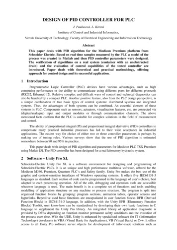
9.Relay Circuit Wiring:Two Form-C contact relays are provided for controlling door lock mechanisms or alarm signaling devices.The relay contacts are rated at 2 A @ 30 Vdc, dry contact configuration. Each relay has a Common pole(C), a Normally Open pole (NO) and a Normally Closed pole (NC). When you are controlling the deliveryof power to the door strike, the Normally Open and Common poles are used. When momentarilyremoving power to unlock the door, as with a mag lock, the Normally Closed and Common poles areused. Check with local building codes for proper egress door installation.Door lock mechanisms can generate EMF feedback to the relay circuit that can cause damage andpremature failure of the relay. For this reason, it is recommended that either a diode or MOV (metaloxide varistor) be used to protect the relay. Wire should be of sufficient gauge to avoid voltage loss.From the Auxiliary output, the EP1501 can provide 12 Vdc power for external devices provided that themaximum current is not exceeded. See the specifications section for details. If a local power supply isused, it must be UL Listed Class 2 rated.Relay Circuit Wiring Diagrams:Diode Selection:1Diode current rating: 1x strike currentDiode breakdown voltage: 4x strike voltageFor 12 Vdc or 24 Vdc strike, diode 1N4002(100V/1A) typical.NO1-CTB5NCNO2-CNCMOV Selection:1NO1-CTB5NCClamp voltage: 1.5x Vac RMS.Use UL recognized MOV with appropriateratingsNO2-CNC10. Memory Backup Battery:The SRAM is backed up by a rechargeable battery when input power is removed. This battery shouldretain the data for a minimum of 3 days. If data in the SRAM is determined to be corrupt after power up,all data, including flash memory, is considered invalid and is erased. All configuration data must be redownloaded.Note: The initial charge of the battery may take up to 48 hours to be fully charged.Mercury Security 2014EP1501DOC 10107-0036REV 1.07Page 7
11. Status LEDs:Power-up: All LED's OFF.Initialization:LED's 1, 2, 3, 4, 5, 6, and 7 are sequenced during initialization. LED's 1, 3, and 4 are turned ON forapproximately 1.5 seconds after the hardware initialization has completed, then the application code isinitialized. The amount of time the application takes to initialize depends on the size of the database,about 3 seconds without a card database. Each 10,000 cards will add about 3 seconds to theapplication initialization. When LED's 1, 2, 3 and 4 flash at the same time, data is being read from orwritten to flash memory, do not cycle power when in this state.If the sequence stops or repeats, perform the Bulk Erase Configuration Memory procedure in section 4.If clearing the memory does not correct the initialization problem, contact technical support.Running:After initialization is complete, the LEDs have the following meanings: At power up, LEDs 2 through 7are turned ON then OFF in sequence.LED12DESCRIPTIONOff-Line / On-Line
Subnet Mask: 255.255.0.0 Default Gateway: 192.168.0.1 DNS Sever: 192.168.0.1 Host port: IP server, no encryption, port 3001, communication address: 0 4. Bulk Erase Configuration Memory: The bulk erase function can be used for the following purposes: Erase all configuration and cardholder database (sanitize board) Update OEM default parameters after OEM code has been changed Recover from .