Transcription
28Rapid manufacturing of dinnerwareR.K.L. Gay, C.K. Chua and W: HoheiselGintic Institute of Manufacturing TechnologyNanyang Avenue, Singapore 63979865-799549J(P), 65-7916377 (F), grobertgay@ntu.edu.sgAbstractComputer usage in the ceramic dinnerware industry bas largely been confined to wordprocessing, spreadsheets, database, payroll, inventory and statistical process control.CAD/CAM or Computer Aided Design and Computer Aided Manufacturing is slowlygaining ground in this industry. The relatively high speed of generating physicaldesigns from conceptualization using CAD/CAM and Rapid Prototyping has suggestedtheir use for the decoration of ceramic dinnerware. A CAD/CAM system developedfor the design and manufacture of patterns to be decorated on ceramic dinnerware isdescribed in this paper.An industrial case study featuring ceramic dinnerware prototypes is carriedout and presented to illustrate the various advantages. These advantages includesignificant time and cost savings. It also avoids the heavy reliance on traditionalpractices, and the experience and skills of craftsmen. The major contribution of theresearch is an innovative approach from art to part or, from conceptualization torealization, for the decoration of ceramic dinnerware. The solution of 3 Dimensionaldecoration and application of rapid prototyping are also described.KeywordsCeramic dinner, rapid prototyping, rapid manufacturing, CAD/CAM, craftsmenComputer Applicatioos in Production and Engineering. F. Plonka and G. Oiling (Eds.)C IWI JFIP. Published by O!apman & Hall
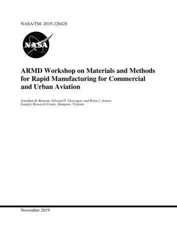
Rapid manufacturing of dinne1ware1311INTRODUCTIONThere are presently several commercially-available software systems forproduct design for a particular range of industries which include ceramictableware (Chua, et. al., 1993), glassware, bottle making, both plastic andglass, jewelry (Lee, et.al., 1992), packaging, food processing, for moldedproducts and products produced from forming rolls, coins and badges,and embossing rollers. All of these industries share a common problem:most of their products have elements of complex engraving or low reliefon them. Traditionally, such work is carried out by skilled engraverseither in-house, or more often by a third-party sub-contractor, workingThis process is costly, open to unwantedfrom 2D artwork.misinterpretation of the design by the engraver and most importantly,lengthens the time of the design cycle.The CAD/CAM revolution has boosted the production and theperformance of many industries everywhere for the past 15 years.However, its applications in the above industries are still at their infancystage. Prototyping is still very much a manual process, which relieslargely on the skills of an experienced craftsman who uses handtools suchas a small chisel to carve and shape the model out of a plaster block.Little attention has been focused on the use of quick and accurate rapidprototyping equipment for building prototypes in this industry.The use of CAD/CAM and Rapid Prototyping (RP) technologiessuch as Stereolithography Apparatus (SLA) and Laminated ObjectManufacturing (LOM) reduces the time required for design modificationsand improvement of prototypes. The steps involved in the art to partprocess are described in the following sections.2SCANNING OF ARTWORKThe function of scanning software is to automatically or semiautomatically create a 2D image from 2D artwork. It would normally beapplied in cases where it would be too complicated and time consumingto model the part from a drawing using existing CAD techniques.The 2D artwork is first read into ArtCAM, the CAD/CAM systemused for the project, using a Sharp JX A4 scanner. Figure 1 shows the2D artwork of a floral design, which has been generated using theThis combination of hardware andcircular adaptation, routinely.software allows for the direct production of a standard image from theartwork, which can be read directly into ArtCAM. The 2D artwork insuch instances represents the designs to be used on the face of tablewareitem such as a dinner plate.
312Figure 1 2D artwork.In the ArtCAM environment, the scanned image is first reducedfrom a color image to a monochrome image with the fully automatic"Gary Scale" function . Alternatively, the number of colors in the imagecan be reduced using the "Reduce Color" function. A color palette isprovided for color selection and the various areas of the images arecolored either using different sizes/types of brushes or the automaticflood fills function.3GENERATION OF SURF ACESThe shape of a dinnerware is modeled to the required dimensions in theCAD system for model building. A triangular mesh file is producedautomatically from the 3D model. This is used as a base onto which therelief data is wrapped and later combined with the relief model to formthe finished part.4GENERATION OF 3D DECORATION RELIEFSThe next stage in creating the 3D-decoration relief is to assign each colorin the image a shape profile. There are various fields which control theshape profile of the selected colored region, namely, the overall generalshape for the region, the curvatures of the profile (convex or concave),the maximum height, base height, angle and scale.There are three possibilities for the overall general shape; a planeshape profile will appear completely flat, whereas a round shape profilewill have a rounded cross section and lastly, the square shape profile willhave straight angled sides. For each of these shapes, there is an option todefine the profile as either convex or concave.The square and round profiles can be given a maximum height.If the specified shape reaches this height, it will 'plateau' out at thisheight giving in effect a flat region with rounded or angled corners,
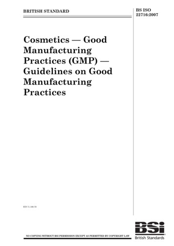
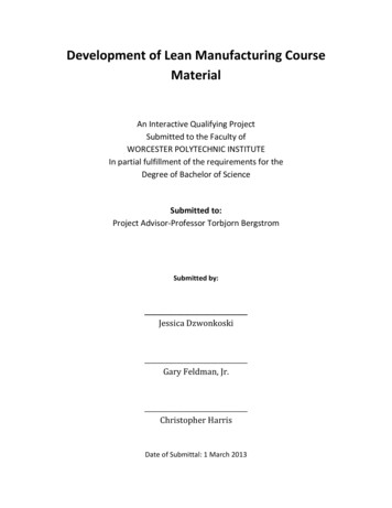
Rapid manufacturing of dinnerware313depending on whether a round or square shape was selected for theoverall profile respectively.The overall profile height which covers the respective region canbe controlled by specifying the required angle of the profile whichrepresents the tangent angle of the curve at the edge of the region. Analternative to control the overall profile height is to use the 'scale'function to flatten out or elevate the height of the shape profile. Therelief detail can be examined in a dynamic Graphic Window within theArtCAM environment itself. Figure 2 illustrates the 3D-decoration reliefof an artwork.Figure 2 3D-decoration relieves of an artwork .5WRAPPING OF RELIEFS ON SURF ACESThe 3D-decoration relief is next wrapped onto the triangular mesh filegenerated from the tableware plate surfaces using the command Wrap.This is a true surface wrap and not a simple projection. The wrappedrelief is also converted into triangular mesh. The triangular mesh filescan be used to produce 3D model suitable for color shading andmachining. The two sets of triangular mesh files, of the relief and thecoin shape, are automatically combined. The resultant model file can becolor-shaded (see figure 3) and used by the SLA to build the prototype.Figure 3 Color-shaded resultant model file.
3146CONVERTING TRIANGULAR MESH FILES TO AN STLFILEThe STL format is originated by 3D System Inc. as the input format tothe SLA, and has since been accepted as the de facto standard of inputfor Rapid Prototyping systems. Upon conversion to STL, the object'ssurfaces are triangulated, which means that the STL format essentiallyconsists of a description of inter-joining triangles that enclose the object'svolume. The triangular mesh files are also triangulated surfaces,however, of a slightly different format. Therefore, an interface programwritten in Turbo-C language is developed for the purpose of conversion.The converted triangular file adheres to the standard STL format. It hasthe capability of handling triangular files of huge memory size.7BUILDING OF MODEL BY RAPIDPROTOTYPINGMETHODSMany computer-aided manufacturing methods are available such as CNCmachining and rapid prototyping (RP) methods. However, for complex3D shapes, the CNC machining will be disadvantaged when compared toRP. Coupled with complex engineering relieves where a large amount ofremoval is required and yet the machining cutter diameter must be smallto reach those small intricate relieves, rapid prototyping has a definiteedge. Rapid prototyping, though, has the disadvantage of limitedmaterials. If, however, given a restricted material type, the functions andapplications - design, engineering and manufacturing (or tooling) - canstill be carried out, then rapid prototyping would have proved itsusefulness and relevance.While many RP methods are available commercially (Chua,1997), the world's top two selling RP machines are used in the study.They are the SLA (number I) and LOM. The SLA has the advantages ofbeing a pioneer and a proven technology with many excellent case studiesavailable. It is also advantageous to use in tableware design as thematerial is translucent and thus, it allows designers to view the internalstructure and details of tableware items like tea pot and gravy bowls. Onthe other hand, the use of LOM has also its own distinct advantages. Itsmaterial cost is much lower and because it does not need support in itsprocess (unlike the SLA), it saves a lot of time in both pre-processing(deciding where and what supports to use) and postprocessing (removingthe supports). The use of both systems allows the evaluation of bothsystems for ceramic tableware. The main criteria for evaluation are speed
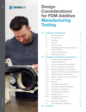
Rapid manufacturing of dinnerware315(time for pre-processing, building and postprocessing), accuracy andsurface finish, and suitability for tooling applications.7.1Using the SLACalifornian company 3D System Inc., pioneered the RP technology whenthey released their commercial RP system in December 1988 - the SLA250 model of their Stereolithography Apparatus (SLA). Stereolithographytechnology was first developed by Chuck Hall, 3D's founding president,in 1982.Stereolithography works by using a low-power HeliumCadmium laser or an Argon laser to scan the surface of a vat of liquidphotopolymer which solidifies when struck by a laser beam. The dinnerplate design with its floral relieves is built using the SLA and the resinmodel is shown in figure 4.Figure 4 Dinner plate design built using the SLA.7.2Using the LOMHelisys, Inc. was founded in 1985 with a charter to provide state-of-the-art, threedimensional modeling capability to a wide range of industrial applications. EarlyR&D activities were financed in large part by DARPA grants, resulting in thedevelopment of the Laminated Object Manufacturing (LOM) process. Helisysintroduced the LOM machines in 1991. The dinner plate design with its floralreliefs are built using the LOM and the paper model is shown in figure 5.Figure S Dinner plate design built using the LOM.
3168EVALUATION OF THE SLA'S AND LOM'S MODELSAND PROCESSES8.1Technical evaluationTechnical evaluation is done through the execution of a benchmark test.The benchmark test piece, in this case the dinner plate, is analyzedthrough some tests including visual inspection and dimensionalmeasurement. In general, two types of measurements can be takennamely, main (large) measurements and detailed (small) measurements.The record of the measurement results is based on the deviationsof the built part from the CAD model. These deviations of both the mainand detailed measurements are tabulated for both the SLA and the LOM.The record of the time results is based on three components - datapreparation, building time and postprocessing. The total time is based onthe addition of the three components. A Table of all four times resultscan be tabulated for both the SLA and the LOM. The time component byitself gives one an idea of the length required for a task and directlyaffects the cost factor. Therefore, the time data can become useful for afull economic justification and cost analysis.The measurements taken are linear dimensions - diameters,heights and thicknesses. Two parts of the test piece are considered forevaluation. The first part includes the plate's top and base surfaces. Thesecond part is the delicate design of the floral patterns which includes theflowers, leaves and others. The results are sub-divided into mainmeasurements ( 10 mm) and detailed measurements ( 10 mm). Forboth the readings, the deviations from the actual reading are computedand tabulated. The deviations for both the measurements are compared.8.2Results of technical evaluationFrom visual inspection, it is apparent that the floral patterns of the LOMpart are more distinct and correctly formed than those of the SLA part.Even under close examination, the flowers, leaves and stems on the SLAmodel are indistinguishable. As the focus of the research is on the 3Ddecoration, this means that the LOM model meets the requirementswhereas the SLA model does not. Tables 1 and 2 list the measurementstaken and their deviations from the nominal values. The Cs (diameters)and Ts (thicknesses) are taken with a vernier caliper and the Hs (heights)a height gauge.The reason for taking two values each of the diameter, forexample, Cl and C2 is for the purpose of establishing the circularity of
Rapid manufacturing of dinnerware317the plate. For the same reason, two values of the height H1 and H2 aretaken as seen in Table 1. Similarly, in Table 2, several values of theplate thickness are taken off different parts of the plate. The results showthat LOM displayed better accuracies or lower deviations as compared tothe SLA for most of the main measurements and all of the detailedmeasurements. In particular, the T values for the LOM model are veryconsistent, unlike those of the SLA model.Table 1 Main measurements ( 10mm) of the 2 benchmark test piecesDesign Dimensionsmm)TopC1186SurfaceC2 186ofC3130DinnerC4 130H1Plate27H227BaseC582SurfaceC682of Dinner H318PlateH418Main MeasurementsMeasurements .6918.5619.0618.71Deviations e l Detailed measurements ( lOmm) of the 2 benchmark test piecesDetailed MeasurementsDesign Dimensions (mm)Measurements dDeviations 90.080.09-0.22NA
3188.3Eeonomieal evaluation and other considerationsBesides technical evaluation, economical evaluation is also important.The cost of a machine or a part made by the machine is an importantfactor. Compared to SLA, the LOM is a much cheaper machine, at aboutUS 100,000 cheaper. In addition, the material cost of paper used by theLOM is cheaper than the photosensitive polymer used by SLA. In fact,amongst all commercial rapid prototyping systems, the LOM has probablythe lowest material cost.In terms of the speed of processing and building a part, it istypical to categorize into: Pre-processing, Building and Postprocessingtimes. Pre-processing time is the time taken to prepare, verify andcorrect the data file (usually an STL file), as well as the time taken tospecify slicing and building parameters and setup the machine forbuilding. Building time is strictly the time taken for the machine to buildthe part from beginning to end. Finally, postprocessing is taken toinclude all activities after building. For example, activities such asremoval of excess resin, cleaning using solvent, removal of supports,posturing, etc., are required for the SLA model. For the LOM process, itmeans removing all the excess wood/paper which can be fairly tediousbecause care is needed not to damage the part.Table 3 shows the results obtained from the building of thedinner plate model. In all categories, the LOM takes longer than theSLA. However, the difference is not very significant. Thus, though interms of the labor cost, the SLA will cost less, the higher cost of the SLAand its photosensitive resin make it more economical to use the LOM.This is also confirmed by service bureau sources in Singapore andGermany, where the typical charge for a SLA model is 1Y2 - 2 times morecostly than a LOM model for the same part.Table 3 Results of processing times for the SLA and LOM alSLA0.5 hours15.5 hours2 hours18 hoursLOM5 minutes18 hours4 hours22 hours and 5 minutesOther advantages associated with the LOM process includes thefact that it is clean and can operate in an office environment. Materialused such as paper need not be shielded from sunlight and does not havean objection smell. Finally, supports are not required in the process,
Rapid manufacturing of dinnerware319making it less constrained in the decision process of orientating a part forbuilding.9CONCLUSIONThe research and development work carried out indicates that a tablewaredesigner can use CADCAM for the decoration of tableware items bymolded or incised decoration. Patterns are 3-dimensional (3D) and lie onthe surface of a 3D-tableware item. Using commercial relief creationsoftware, the 3D patterns are generated and mapped onto an alreadymodeled tableware item such as dinner plate. Experiments using rapidprototyping (RP) technology have proven to be successful. Amongst themany RP methods, the SLA and LOM were used for the trials. From theresults and based on technical and economical evaluation, the LOM waschosen for its better performance and affordability.10REFERENCESChua, C.K., Hoheisel, W., Keller, G., and Werling, E. (1993) Adaptingdecorative patterns for ceramic tableware. Computing andControl Engineering Journal 4(5): 209-217.Lee H.B., Ko, M.S.H., Gay, R.K.L., Leong K.F. and Chua C.K. (1992)Using computer-based tools and technology to improve jewelrydesign and manufacturing. International Journal of ComputerApplications in Technology 5(1): 72-80.Lee, Han Boon. (1993) Computer-aided and manufacturing for thejewelry industry. M.Eng. diss., Nanyang TechnologicalUniversity, Singapore.Chua, C.K. and Leong K.F. (1997) Rapid prototyping: Principles andapplications in manufacturing John Wiley.11BIOGRAPHYDr Robert Gay is the Director of Postgraduate Studies at the GinticInstitute of Manufacturing Technology, Singapore. Dr Chua Chee Kai isa senior lecturer with the School of Mechanical and ProductionEngineering in Nanyang Technological University, Singapore. ProfWolfgang Hoheisel is the Director of the Steinbeis Centre of ComputerIntegrated Manufacturing at Karlsruhe, Germany.
The 2D artwork is first read into ArtCAM, the CAD/CAM system used for the project, using a Sharp JX A4 scanner. . software allows for the direct production of a standard image from the artwork, which can be read directly into ArtCAM. The 2D artwork in such instances represents the designs to be used on face of tableware item such as a dinner .