Transcription
Continuing Education: TechnologyELEVATOR HOISTWAY EQUIPMENT:Mechanical and Structural Design, Part IIby George W. GibsonLearning ObjectivesAfter reading this article, you should: Have developed a basic understanding of the construction,terminology and characteristicsof steel wire ropes. Have learned that the two mostimportant criteria affecting thelife of suspension (hoist) ropesare the sheave diameters andrope lubrication. Understand that rope externaland internal wear continues overthe service life of the ropes, andthat the residual strength of theropes decreases accordingly. Have developed a basic understanding of the principles of ropetraction; specifically, that theamount of available tractionbetween the ropes and groovesmust always exceed the requiredtraction to move the hoistwaymasses in a controlled and safemanner. Have developed a basic understanding that the amount ofavailable traction between thedrive sheave grooves and suspension ropes is a function ofthe actual coefficient of frictionbetween them, the grooveshape, and the arc of contactthat the ropes make as theywind over the drive sheave. Understand that the major inherent safety feature of a traction drive is its ability to losetraction if either the car or counterweight bottoms on its buffer. Understand that the numberand size of hoist ropes on anyelevator is a function of thestrength of the ropes and thefactor of safety, and the groovepressures developed betweenthe ropes and groove surfaces. Have learned that elevator enclosures (cabs) must be strongenough to withstand the forcesimposed during normal service,as well as, during safety application and buffer engagement,and that their materials mustmeet fire protection requirements. Have learned that there areseveral configurations of elevator doors. Have learned the functions ofthe car door operator, and thatthe resulting door closingspeed caused by the operatormust be limited, depending onthe type of door reopening device used. Understand that the ridingquality of an elevator is basedon the travel path imposed bythe guide rails, as well as theposition of loads inside the car,rope vibrations and air pressures in the hoistway. Have developed a basic understanding about the effects ofbuilding sway on the elevatorsystems, principally the hoistand compensating ropes, andtraveling cables.Value: 2 contact hours(0.2 CEU)This article is part of ELEVATOR WORLD’sContinuing Education program. Elevator-industrypersonnel required to obtain continuing-educationcredits can receive two hours of credit by readingthe article and completing the assessment examination questions found on page 113.For this article and more continuing-educationopportunities, visit www.elevatorbooks.comNATIONAL ASSOCIATIONOF ELEVATOR CONTRACTORS Approved by NAEC for CETCERTIFIEDELEVATOR TECHNICIANEDUCATION PROGRAMContinuedApproved by NAESAI for QEIFebruary 2009 ELEVATOR WORLD 91
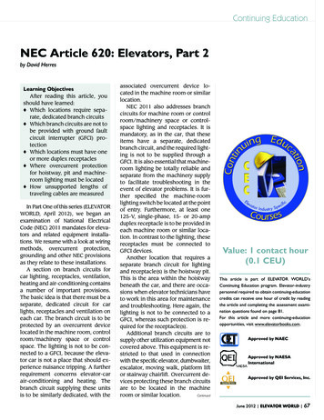
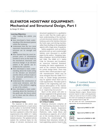
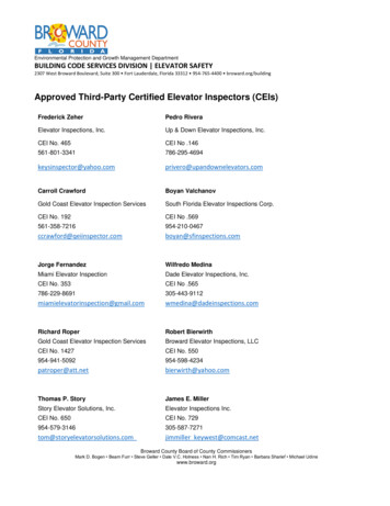
Continuing Education: Technology10. ROPES AND TRACTION:10.1 Steel Wire Ropesand Manufacture:Steel wire ropes used with traction elevators are primarily in twogeneral classifications:A. 8 X 19 Class, which contains eightmetal strands wound around afiber coreB. 6 X 19 Class, which contains sixmetal strands wound around afiber coreEach strand can have 19, 21, 25 or26 individual wires in its configuration. The fiber core is a tightly woundthree-strand rope. It may be made ofvegetable or synthetic fibers.In an elevator wire rope, thearrangement of the wires in the strandswhich determine its specific label isof four types as shown in Figure 30.Taken in the order of predominantusage, the most common is theSeale construction, where eachstrand consists of a comparativelyheavy center wire around which is alayer of nine smaller wires. The outerlayer is supported in the valleys formedby the first layer; hence, both layershave the same number of wires. Bysimple wire count, this strand is designated 1-9-9. The large wires in theouter layer provide abrasion andwear resistance to this type.The filler wire constructions shownare designed to give more strandflexibility. The six small filler wireslaid in between the main wires of theinner layer provide a series of valleysinto which wires of the outer layer fitnicely. There are twice as manywires in the outside layer as in theinside layer. By wire count, this typeis designated: 1-6-6-12.The Warrington construction isless commonly used today. It ismade up of two layers of wire abouta center wire. There are six wires inthe inner layer and 12 in the outerlayer, the outer layer of wires beingalternately large and small. The wirecount designation here is 1-6-12.From the foregoing, it will be seenthat 8 X 19 Seale simply means awire rope of eight strands of Sealeconstruction having 19 wires. Thenumber of wires in the rope is equalto eight times 19, which is equal to152. Generally speaking, the morewires per rope, the more flexible therope. The large outer wires of theSeale construction strand make itcomparatively stiffer than the fillerwire strand, but eight-strand rope ismore flexible than six-strand. So a 6X 25 filler wire has more flexiblestrand construction, but having sixstrands compromises overall ropeflexibility. However, six times 25equals 150 wires, which attests tosubstantial rope flexibility by thegeneral rule of total number of wires.The 8 X 25 filler wire combines bothflexibility factors and it has eighttimes 25, or 200 wires.The elevator wire rope then is sixor eight adjacent steel strands incontinuous helical formation tightlyformed around a fiber rope centerwhich provides internal support. Theterm rope lay is used to designate thedistance along the rope’s length thatFigure 3092Continued WWW.ELEVATOR-WORLD.COM February 2009one strand requires for one completehelical turn around the rope. It is approximately equal to 6.5 times thenominal rope diameter, as shown inFigure 31.Several grades of steel are used inthe manufacture of elevator wireropes. The so-called “iron” rope ismade from relatively soft, low-carbon steel. It is a low strength ropeused mostly for compensationarranged with tie-down. Tractionsteel contains somewhat more carbon and has a tensile strength of160,000 psi, minimum. This is thesteel used for general elevator ropeapplication. In six-strand tractionsteel rope, all of the wires are madefrom traction steel, but eight-strandtraction steel rope is made from acombination of traction steel wiresin the outer layer and special highstrength steel wires for the centerwire and the inner layer. The reasonfor this is that eight-strand rope hasa smaller cross-sectional steel areathan six-strand rope, but both sixand eight-strand traction steel ropeshave the same breaking strength.In line with the construction ofhigh-rise office buildings in the late1950s and 1960s, the need for higherstrength rope was apparent and thewire rope industry responded withextra high-strength traction steelrope. The rope strength was increased 25% to 40% and wire tensilestrength to 220,000 psi, minimum.Whereas 1/2- and 5/8-inch diameterropes were formerly common sizes,now 11/16-, 3/4-, 13/16- and 7/8inch diameter hoist ropes are not uncommon in today’s mega-high-risebuildings. Former high speed hoistFigure 31
rope safety factors required by ASMEA17.1 Code Rule 2.20.3 for passenger service of 11.00 for 700 fpm havereceded into the background as current considerations are for 11.90 at1,600 fpm and higher.A rope is an element which weknow in advance will have to be replaced after a few years of service. Inview of this, the so-called factor ofsafety becomes a judgment factor setby the ASME A17.1 Code of the allowable maximum stress on a ropeduring its expendable life.The strength of a rope is determined by taking a specimen of newrope and pulling it apart on a tensiletesting machine and the factor ofsafety is defined as the ratio betweenthe minimum load necessary tobreak the rope, and the load imposedon it in service. However, after a period of service, changes occur in therope consisting principally of wear inthe outer wires and the formation ofmicroscopic fatigue cracks whichdevelop into broken wires.As this wear process continues,the residual breaking strength decreases, resulting in a correspondingdecrease in the actual remaining factor of safety. When most steel hoistropes have reached the point wherereplacement is necessary due towear, it is not uncommon that thebreaking strength is 60% of the original breaking strength of the ropes intheir new condition.The strength of a new rope then isnot the permanent measure of safety.Safety in ropes is obtained only atthe expense of continued inspectionand their prompt removal at the appearance of signs of approachingfailure. These signs, at present, arethe number of breaks of outer wireson the worst lay length of the rope,as well as the distribution of thesebreaks over the various strands. Another is minimum rope diameterwhen it is reduced due to crown wirewear and core deterioration.The status of a rope is usually determined by physical examination ofits outside appearance. Modern-dayadvances in instrumentation havemade possible the monitoring ofropes on a continuous basis by passing the ropes through a magneticfield from which the remaining steelarea integrity can be checked. Assmaller steel wire rope diameters aredeployed, such monitoring deviceswill gain popularity because of theiraccuracy.The ASME A17.2 Guide for Inspectionof Elevators, Escalators, and MovingWalks gives rules for the inspectionand condemnation of wire ropes. Theservice life of a rope is affected bymany things, but there are two in particular that should be mentioned, i.e.,rope lubrication and sheave diameter.When a rope runs over a sheave,sliding friction occurs between thedifferent wires of the rope, betweenthe strands and the hemp center, and,usually, between the outside wiresand the surface of the sheave. Thisaction causes abrasion of the wiresand a breaking down of the hempcenter. Considerable difficulty wasexperienced in this respect manyyears ago, but improvement in lubrication practice, both in rope manufacture and in elevator maintenance,has acted to reduce these troubles.In lubricating traction drive elevator ropes, we must avoid a lubricantwhich will excessively reduce the coefficient of friction between theropes and sheave. An extreme pressure lubricant or one containinggraphite, for instance, would be veryharmful in this respect. The ideal lubricant should penetrate the strandsof the rope and thicken up enough toremain in place and protect themfrom corrosion, but should not produce a greasy or slippery surface. Ingeneral, lubrication of ropes is recommended when it becomes dry tothe touch, but over-lubrication is tobe avoided.The ASME A17.1 Code Rule 2.24.2specifies that for hoist ropes, nosheave diameter shall be less than40 times the rope diameter exceptthat a ratio of 30 times the rope diameter is permitted for private residence elevators [ASME A17.1 Rule5.3.1.16.2(b)(1)(a)]. The most obvious advantage of a large sheave isthat it reduces the bending stressesin the wires of the rope. Another advantage, not quite so obvious, is thatthe larger the sheave the less the radial pressure between rope andsheave.While a large sheave is thus beneficial from the standpoint of sheavewear and long rope life, it naturallyincreases the cost of the machine. Ina geared machine, it results in moreload on the gear and, in a gearlessmachine, it requires more torquefrom the motor. Thus, we find that,as in so many phases of machine design, the size of the sheave must bea compromise between these conflicting influences.Over the last few decades, elevator wire rope application considerations include preforming, syntheticfiber cores and pre-stretching.Preforming is a wire rope fabrication technique whereby the helicalshape of the strands in its position inthe finished rope is permanentlyformed before the strands and fibercore are assembled into rope. Thenon-preformed wire rope has itswires and strands constrained intheir final position in the rope; therefore, the ends must be held with wirebands called seizings. In non-preformed wire rope, severed wires orstrands will tend to straighten out. Inpreformed rope, they do not. The advantages of preformed rope are increased flexibility and longer usefullife. The disadvantages are increasedrope stretch and greater difficulty indetecting broken wires during maintenance examinations and regulaContinuedtory inspections.February 2009 ELEVATOR WORLD 93
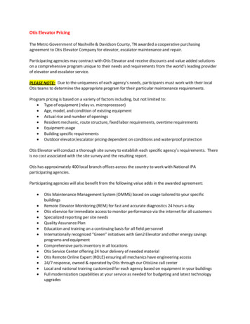
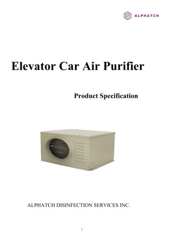
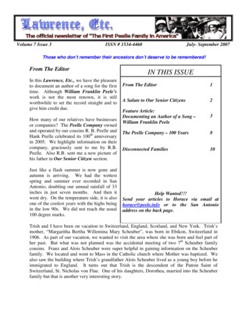
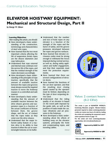
Continuing Education: TechnologyWire ropes with synthetic fibercores have had successful application in oil fields due to their resistance to moisture and prevalent environmental conditions detrimental tonatural fibers. They have been usedfor hoist and compensating rope applications. Steel wire ropes with synthetic cores stretch more than theirfiber core counterparts.Construction stretch is permanentstretch and primarily due to progressive embedding of the wires into thefiber core in the kneading action asnew ropes run over the sheaves.This process is experienced as beingfairly rapid in the early stages afterinstallation of the ropes and diminishes with time over a period from afew months to over a year. Theamount of this stretch can be fairlyaccurately estimated and the newrope cut short to allow for this anticipated stretch. The manufacturer’svalues for estimated stretch of wirerope with fiber core are as follows:6 X 19: 1/2% to 3/4%6-9 inches per 100 feet8 X 19: 3/4% to 1%9-12 inches per 100 feetFor preformed ropes, these figuresmay be increased by 50%.Pre-stretching is an optional finishtreatment of rope at manufacturewhich removes most of the initialstretch (construction stretch). Its additional cost must be weighedagainst the cost of “shorteningropes” when excessive constructionstretch occurs, especially in high-riseinstallations.Figure 3294Continued10.2 Traction:In most mechanical systems, aconsiderable emphasis is placedupon reducing the friction betweenparts. The opposite is true for elevator traction drive machines. In thislatter case, we strive to utilize thisfriction that exists between the hoistropes and the machine drive sheave.The early roped machines utilizeda large drum upon which the hoistropes were wound. As buildings became taller, it was obvious that thewinding drums must become largerand larger. This became the impetusbehind the development of the traction drive. The major inherent safetyfeature of the traction drive machineis its ability to lose traction if eitherthe descending car or counterweighthits its buffer, thereby preventing themachine from pulling the ascendingmass into the building overheadstructure.The ASME A17.1 Code defines atraction machine as: “a direct drivemachine in which the motion of thecar is obtained through friction between the suspension ropes and atraction sheave.”ASME A17.1 Rule 2.16.8 stipulatesthat traction elevators be designedand installed to safely lower, stopand hold the car under rated loadand under certain overloads.ASME A17.1 Rule 2.24.2 furtherrequires that drive sheaves shall beof metal and provided with finishedgrooves for ropes. The grooves ofsheaves used to transmit power maybe lined with nonmetallic materialprovided that, in the eventthe lining should fail, therewill be sufficient tractionstill available in thegroove to safely stop andhold the car with 125% ofthe rated load. Elastomerlined grooves are permitted as long as these requirements are met. Otis WWW.ELEVATOR-WORLD.COM February 2009ElevatorCo.introduceditspolyurethane groove, known asCable-SaveTM, in the 1970s. Thereare many remaining in service. Future revisions to the ASME A17.1Code are being considered whichwill allow for nonmetallic groovecontact surfaces beyond elastomericmaterials.One of the best examples to showthe advantage of harnessing frictionis seen on the waterfront when aship is docking. A hawser is thrownfrom the ship to the pier and a longshoreman wraps it a few timesaround a capstan. With as little as a30-pound pull by the longshoreman,he can sustain a pull in the rope exerted by the moving ship equal to10,000 pounds, as seen in Figure 32.This action is made possible because of the coefficient of friction existing between the rope and capstan,and also to the number of turns thatthe rope makes as it is woundaround the capstan. Therefore, it canbe seen that traction depends on twocriteria: friction and angle of contact.Figure 33 shows a rope passingover a driving sheave. For the sakeof the example, let us say that theportion of the rope leaving thesheave at point C leads to the carwith a weight of S1 1000 pounds.The portion of the rope leaving thesheave at point D leads to the counterweight with a weight of S2 800pounds. The tension in the ropesvaries from its minimum value of S2Figure 33
800 pounds at D to its maximumvalue of S1 1000 pounds at point C.This is shown by the force vector distribution drawn around the sheave.It is obvious then that somethingmust exist that causes the rope tension to increase from the 800-poundvalue to 1000 pounds betweenpoints D and C. This something iscalled the tractive effort, whereTractive effort S1-S2This tractive effort is based on thefrictional resistance between thesheave and the rope. The amount offrictional resistance has certain limitations, and herein lies the basis forthe theory of the traction drive.Since the rope tensions S1 and S2are unequal, this difference in tensions, referred to above as the tractive effort, produces a phenomenoncalled creep. Creep is the incremental movement of the hoist ropes overtheir arc of contact with the drivingsheave due to the tractive force, thetensile elasticity of the ropes and thefriction work, occurring in the direction of the greater tension, and is independent of the direction of rotation of the driving sheave. Creepexists in all traction systems and isnot to be confused with the loss oftraction.The maximum available tractionthat can be developed in a groove isa function of the actual coefficient offriction between the rope andgroove, the shape of the groove andthe angle of contact that the ropemakes with the circumference of theFigure 34sheave. The required traction for anyelevator is expressed as:S1Required traction –––S2where S1 is greater than S2. Themaximum value of the ratio S1/S2that can occur without the rope slipping over the sheave is called theavailable traction and is expressedasAvailable traction, α e faθwhere e the base of natural logarithms, fa the apparent coefficientof friction which embodies the actualcoefficient of friction and the shapeof the groove, α available traction(dimensionless) and θ the arc ofcontact that the rope makes with thesheave, expressed in radians.Obviously then, the maximumtraction is developed when thequantity, faθ, is maximized as a resultof increasing the apparent coefficient or by increasing the arc of contact or both. Elastomer-lined drivesheave grooves have higher coefficients of friction and afford a very efficient method of increasing theavailable traction.Figure 34 shows a rope runningover a driving sheave and a deflectoras in the more or less typical overhead single wrap traction (SWT) installation. It is evident that, if hoistway layout conditions permitted aFigure 35rope drop, i.e., the horizontal distance from the center of the car hitchto the center of the counterweighthitch without deflector, the maximum arc of contact between therope and sheave would be θ 180 3.14 radians.With the deflector sheave asshown in Figure 34, it is seen that itis possible to obtain a slight increasein θ by lowering the deflector sheaveas much as possible. However, whenthis method still produces insufficient traction, we must resort to thedouble wrap traction (DWT) ropingarrangement as shown in Figure 35,or alter the groove shape to producethe required traction.Whether single wrap or doublewrap roping is used, it is obviousthat there must be sufficient available traction to safely lower, stopand hold the car under all conditionsof load without the ropes slipping. Asnoted above, the available traction isa function of two variables.The hoist ropes, in passing overthe traction machine drive sheave,exert a pressure between the contacting surface of the drive sheavegrooves and the ropes. This pressureis directed radically in the plane ofthe sheave, and its magnitude is afunction of the hoist rope tensionand the diameter of the sheave. Thelarger the sheave diameter, thesmaller the radial pressure per unitlength along the arc of contact thatthe rope subtends on the sheave circumference.This radial force causes a pressuredistribution over the lower boundaryof the rope profile thereby maintaining it in a state of vertical equilibrium. It is physically distributed overthe regions of rope-to-groove contact. Such pressure distributions areshown graphically to a relative scalein Figure 36 for the various grooveconfigurations of round-seat and undercut grooves.ContinuedFebruary 2009 ELEVATOR WORLD 95
Continuing Education: TechnologyReferring to Figure 36, it is seenthat the maximum rope pressure occurs at the bottom of the groove. Inthe cases of the undercut grooves,the line of contact between the ropesand groove is interrupted where thepressure would ordinarily be thegreatest. Therefore, since the verticalsummation of pressure vectors mustbe in equilibrium with the radial forceper unit length of rope, the pressurevectors must be exerted over a smallerregion of groove contact, thereby inducing groove pressures higher thanthose of the round-seat groove. Themaximum rope pressure will occurat the edge of the undercut.The most significant increase intraction can be achieved by changing the groove shape, using the undercut groove, which increases theapparent coefficient of friction. Theround seat groove is used on DWTinstallations, whereas the 90 and 105 grooves were used by Otis and othermanufacturers on SWT machines.While the magnitude of the groovepressure distributions associatedwith each of the grooves as shown inFigure 36 varies, it is to be noted thatin no case does the “actual” rope-togroove coefficient of friction change.However, the “apparent” coefficientis a direct function of the groovepressures and the actual coefficientof friction, and it does change as thegroove shape changes.In conventional traction drives,drive sheaves are furnished withround-seat grooves or undercutgrooves depending upon the required traction that must be developed to safely lower, stop and holdthe elevator. The sheave material isusually a high grade of cast iron.From the standpoint of getting maximum rope life, it would be desirableto furnish round-seat grooves in allcases. However, in order that sufficient traction be developed betweenthe steel rope and iron sheave, undercutting the bottom of the ropegroove is required, thereby increasing the groove pressures upon whichthe higher available traction isbased. While this conventionalmethod provides the required traction, the attendant rope life andsheave life is greatly reduced.The mathematical proof of thetheory of traction is beyond thescope of this brief presentation;however, the proof concludes thefollowing:1. The available traction can be increased by increasing the arc ofcontact that the rope subtendswith the sheave.2. The available traction can be increased by increasing the angle ofundercut in the sheave groove.3. The available traction can be increased by increasing the actualcoefficient of friction between therope and groove surface.There is, of course, a limit on themaximum undercut angle since thelarger the undercut, the less supportthe rope receives from the groove, andtherefore, the less load we can putFigure 3696Continued WWW.ELEVATOR-WORLD.COM February 2009on the ropes without causing rapidsheave wear and rapid rope failure.For this reason, the allowable loadper rope decreases with a corresponding increase in the undercut angle.There are two design criteria forthe selection of the number of ropesneeded:1. Factor of safety, as prescribed byASME A17.1 Rule 2.20.3.2. Limiting rope-to-groove pressure.Where round seat grooves areused, the rope selection is based onthe required factor of safety. However,when undercut grooves are furnished,the rope selection will be based onthe allowable rope-to-groove pressure. Each manufacturer decides thislatter point. It should be noted thatthe European elevator code, EN 811: 1986, codified the limiting pressure from the following formula:Metric:12.5 4 V[ –––––––––––]1 Vrpmax rwhere: pmax Specific rope-to-groovepressure (Newtons per square millimeter)vr Rope speed (mps)Expressed in terms of imperial units,this formula becomes:pmax [3.125 1 Vr196.85Vr196.85]where: pmax Specific rope-to-groovepressure (psi)vr Rope speed (fps)The Europeans discontinued therope-to-groove formula in theEN 81-1: 1998 Code. Furtherresearch into Hyman’s 1926theory showed that this wasnot a representative conditionfor most passenger elevators,and that the pressures shouldbe lower than this formulawould yield, leaving it to themanufacturers to set theirown limits.
The use of compensating ropes orchains should be covered briefly inconcluding this subject since theirapplication directly relates to traction.The purposes of compensation are:1. To reduce the required traction relations2. To permit best sheave groove forlongest rope life (undercut grooves)3. To reduce the required torque onthe elevator driving machine motor4. To keep the load on the machineconstant, irrespective of the position of the car in the hoistwayThere are no requirements establishing a maximum permissibleamount of rope slippage since thereis no way to establish such a limitation that would be suitable for all designs, all capacities and all speeds ofelevators. Some rope movement relative to the drive sheaves is normalfor all traction elevators and typicallymanifests itself as creep, which wasdiscussed above.11. ELEVATOR ENCLOSURES:ASME A17.1 Code Section 2.14 requires that elevator cars be permanently enclosed on all sides, exceptthe sides used for entrance and exit,and on the top. Further, the enclosure must be securely fastened to thecar platform such that it cannot become displaced in ordinary serviceor upon the application of the carsafety or on buffer engagement.The ASME A17.1 Code Rule2.141.3 further requires that the enclosure be strong enough to withstand a force of 75 pounds/feet (330Newtons) applied horizontally at anypoint on the walls of the enclosureand that the deflection will not reduce the running clearance betweenthe car and counterweight, specifiedin ASME A17.1 Section 2.5.1, belowthe minimum, nor to exceed oneinch (25 millimeters).Car enclosure tops must be designedand installed as to be capable of sustaining a load of 300 pounds on anysquare area two feet on a side and100 pounds applied at any point.Materials for car enclosures andcar enclosure linings must be metalor glass, or conform to the fire protection requirements that the flamespread rating be within the range of0–75, and the smoke-developmentrating be within the range of 0–450.Samples of the cab materials in theirend-use configuration must betested in accordance with the requirements of ASTM E-84, ANSI/UL723, NFPA 252 or CAN/ULC-S102.2,whichever is applicable in the jurisdiction in which the elevator is beinginstalled. The reader is referred toASME A17.1 Rule 2.14.2 (latest edition) for the complete provisions.The two types of enclosures are passenger elevator cabs and freight elevator enclosures, discussed below.The general door arrangementsare center-opening doors, shown inFigure 37, wherein two door panelsmove in opposite directions andmeet in their closed position at thecenter of the opening. Single-slidedoors are frequently used on smallercars and consist of a single movingdoor. Two-speed doors are frequently used on hospital elevatorswhere a large door opening is required to accommodate stretchersand beds. In this latter door arrangement, one door moves at twice thespeed of the other. Typical doorarrangements are shown in Figure38, taken from NEII Building Transportation Standards and Guidelines.These can be seen in more detail athttp://www.neii.org.Continued11.1 Passenger Elevator Cabs:Passenger cabs are generally designed and constructed to meet aesthetic requirements primarily, andstructural parameters secondarily. Intheir most basic form, passengercabs will consist of a car front whichcontains the door assembly and caroperating fixtures, the car sides andrear sections, ceiling (which may further embody a suspended arrangement), and an emergency top exit. Inaccordance with the latest ASMEA17.1 Code, side emergency exitsare prohibited. Depending on thedecorative treatments, hang-on panels might be installed on a metalskeleton frame or similar structuralarrangement. Handrails would beapplied last. A typical cab is shownin Figure 37.Figure 37Figure 38February 2009 ELEVATOR WORLD 97
Continuing Education: Technology11.2 Freight Elevator Enclosures:The principal parts of a freightenclosure are:A. Enclosure panelsB. Extension panelsC. Car topThe specific designs will vary fromcompany to company; however,the primary requirements are thatthey be structurally sound to meetthe loading conditions discussedabove. The usual constructionembodies sheet steel panels suitablyreinforced.12. DOOR OPERATORS:Today, all passenger elevator dooroperators are of the “master” type.This means that the door operatorcarried on top of the elevator caboperates the cab car door and eachof the hoistway doors that the elevator serves.The only hoistway door that canbe opened is the one at the landingat which the elevator stops; thus, youare assured of a very safe situation.Figure 39 shows an example of anOtis 6970 door operator located in itsnormal position above the elevatorcab. Note the swinging arms that areattached to the door assembly. Asthe arm swi
construction having 19 wires. The number of wires in the rope is equal to eight times 19, which is equal to 152. Generally speaking, the more wires per rope, the more flexible the rope. The large outer wires of the Seale construction strand make it comparatively stiffer than the filler wire strand, but eight-strand rope is more flexible than .