Transcription
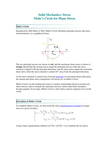
Mohr-Coulomb ModelTuesday, September 11, 201212:43 PMSteven F. Bartlett, 2010Mohr-Coulomb Model Page 1
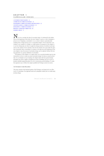
Post-Failure - Dilation AngleWednesday, August 17, 201112:45 PMHow does dilatancy affect the behavior of soil?The angle of dilation controls an amount of plastic volumetric strain developedduring plastic shearing and is assumed constant during plastic yielding. The valueof ψ 0 corresponds to the volume preserving deformation while in shear.Clays (regardless of overconsolidated layers) are characterized by a very lowamount of dilation (ψ 0). As for sands, the angle of dilation depends on theangle of internal friction. For non-cohesive soils (sand, gravel) with the angle ofinternal friction φ 30 the value of dilation angle can be estimated as ψ φ-30 . Anegative value of dilation angle is acceptable only for rather loose sands. In mostcases, however, the assumption of ψ 0 can be adopted.Pasted from elp/fem/angle-of-dilation/ No dilatancy, dilatancy angle 0. Note thatthe unit square has undergone distortionsolely.Dilatancy during shear. Note that the unitsquare has undergone distortion andvolumetric strain (change in volume). Steven F. Bartlett, 2011Mohr-Coulomb Model Page 2
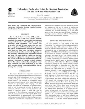
Post-Failure - Dilation Angle (cont.)Wednesday, August 17, 201112:45 PMSoils dilate (expand) or contract upon shearing and the degree of this dilatancycan be explained by the dilatancy angle, .This element is dilatingduring shear. This isplastic behavior.(Salgado: The Engineeringof Foundations, p. 132)The dilatancy angle can be calculated from the Mohr's circle of strain, or fromthe triaxial test, see later. It can also be estimated from the following formulas,if the volumetric and maximum shear strain increments are known.(Salgado: The Engineering of Foundations, p. 132) Steven F. Bartlett, 2011Mohr-Coulomb Model Page 3
Post-Failure Behavior, Dilation Angle from Triaxial TestTuesday, September 11, 201212:43 PM(Flac v. 5 User Manual)(Flac v. 5 User Manual)Steven F. Bartlett, 2010Mohr-Coulomb Model Page 4
Post-Failure Behavior, Dilation Angle from Triaxial TestTuesday, September 11, 201212:43 PM(Salgado: The Engineering of Foundations, p. 132)Plane strain conditions p - c 0.8 p P peak friction angle (used in FLAC as command friction C critical state friction angle ( approx. 28 to 36 degrees quartz sand) P peak dilation angle (used in FLAC as dilation )Triaxial (i.e., axisymmetrical) conditions p - c 0.5 pSteven F. Bartlett, 2010Mohr-Coulomb Model Page 5
Plane Strain vs. Triaxial Strain ConditionsWednesday, August 17, 201112:45 PMTriaxial StrainPlane Strain(See Eq.5-16 inbook torelate pand c)Valid only for aconfining stress of1 atm p peakfriction angle C criticalstate frictionangle(Salgado: TheEngineering ofFoundations) Steven F. Bartlett, 2011Mohr-Coulomb Model Page 6
Estimation of the peak friction angle from critical state friction angleWednesday, August 17, 201112:45 PMIteration to estimate peak friction angle from stress state and void ratio Practical application If we know the critical state friction angle of a soil, the horizontal earth pressurecoefficient Ko, and the relative density of the deposits, we can estimate the peakfriction angle. This is valuable for design because most often, the peak frictionangle is used to define the strength of the soil in foundation calculations.Mean stress at the end of consolidation phase forKo condition(Salgado: The Engineering of Foundations) Steven F. Bartlett, 2011Mohr-Coulomb Model Page 7The mean effectivestress (in situ) was usedto calculate the averageconsolidation stress forthe sample because thesoil has beenanisotrophicallyconsolidated in situ.Anisotropicconsolidation betterrepresents the actualconditions. Suchconsolidaton is alsocalled Ko consolidated.
Estimation of the peak friction angle from critical state frictionangleWednesday, August 17, 201112:45 PM(Salgado: TheEngineering ofFoundations)Note that in the above example, the peak friction angle calculate from theabove equation, is not consistent with the assumed value of 40 degrees. Thus,the mean stress of 30.6 is somewhat inconsistent with the calculated peakfriction angle of 39.1 degrees. Hence, another iteration is required. This isdone by adjusting the assumed peak friction angle to 39.1 degrees andrecalculating the mean stress and resulting friction angle until convergence isreached. In practice, friction angles are usually reported to the nearest wholenumber, so once the iteration converges to a stable whole number value, theniteration can stop.ORWe can use the charts on the next page to estimate the difference betweenthe peak and critical state friction angle as a function of effective confiningstress. Steven F. Bartlett, 2011Mohr-Coulomb Model Page 8
Estimation of the peak friction angle from critical state frictionangleWednesday, August 17, 201112:45 PM(Salgado: The Engineering of Foundations) Steven F. Bartlett, 2011Mohr-Coulomb Model Page 9
Mohr - Coulomb Model in FLACTuesday, September 11, 201212:43 PMInitial StateDeformed StateSteven F. Bartlett, 2010Mohr-Coulomb Model Page 10
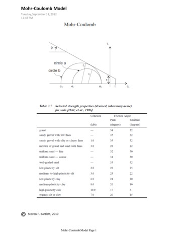
Mohr - Coulomb Model in FLACTuesday, September 11, 201212:43 PMAxial Stress versus Axial StrainDoes this relationship show the correct values of:a. Cohesion at failure?b. Young's modulus?Verify these questions by used the above plot to confirm thatcohesion and Young's modulus have been appropriatelyrepresented.Steven F. Bartlett, 2010Mohr-Coulomb Model Page 11
FLAC Code for ModelTuesday, September 11, 201212:43 PMconfigset large; large strain modegrid 18,18; for 18" x 18" EPS blockmodel mohrprop density 20 bulk 2.08e6 shear 2.27e6 cohesion 50e3 friction 0 dilation 0 tension 100e3; EPS properties;ini x mul 0.0254; makes x grid dimension equal to 0.0254 m or 1 inchini y mul 0.0254; makes y grid dimension equal to 0.0254 m or 1 inch;fix y j 1; fixes base in y direction onlyfix x y j 1 ;fixes base in x and y direction only;fix y i 8 12 j 1 ; fixes only part of basehis unbal 999;apply yvelocity -5.0e-6 from 1,19 to 19,19 ;applies constant downward velocity to simulate astrain-controlled testapply yvelocity -5.0e-6 xvelocity 0 from 1,19 to 19,19 ;applies constant downward velocity tosimulate a strain-controlled testdef verticalstrain; subroutine to calculate vertical strainwhilesteppingavgstress 0avgstrain 0loop i (1,izones)loop j (1,jzones)vstrain ((0- ydisp(i,j 1) - (0 - ydisp(i,j)))/0.0254)*100 ; percent strainvstress syy(i,j)*(-1)avgstrain avgstrain vstrain/18/18avgstress avgstress vstress/18/18end loopend loopendhis avgstrain 998his avgstress 997;step 3000history 999 unbalancedcycle 3000Steven F. Bartlett, 2010Mohr-Coulomb Model Page 12
friction angle. This is valuable for design because most often, the peak friction angle is used to define the strength of the soil in foundation calculations. Practical application Iteration to estimate peak friction angle from stress state and void ratio The mean effective stress (in situ) was used to calculate the average