Transcription
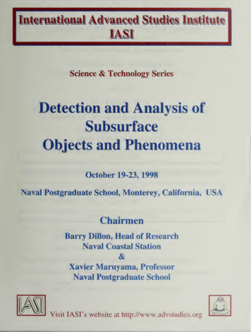
Subsurface Exploration Using the Standard PenetrationTest and the Cone Penetrometer TestJ. DAVID ROGERSDepartment of Geological Sciences & Engineering, 125 McNutt Hall,University of Missouri–Rolla, Rolla, MO 65409-0230Key Terms: Site Exploration, Site Characterization,Subsurface Exploration, Drilling, Standard Penetration Test, Cone PenetrometerABSTRACTThe Standard Penetration Test (SPT) and ConePenetrometer Test (CPT) have become industrystandards for subsurface geotechnical investigationsusing small diameter ( 8-in. [20-cm]) borings andsoundings. Both procedures have evolved overa period of 100 and 70 years, respectively, and havebeen adopted as ASTM standards. Each procedurehas certain advantages over the other, but both canelicit incorrect data under particular subsurfaceconditions that are often overlooked, depending onthe experience of field personnel operating or loggingthe tests. This paper seeks to explain the operativeassumptions employed in both procedures, highlightthe various corrections that are commonly employed,and warn the reader of common errors in interpretation. The article concludes by stating that, undermost conditions, the joint employment of SPT andCPT together has the greatest potential for characterizing sites correctly.INTRODUCTIONThe purpose of a subsurface exploration program is toinvestigate those underlying features suggested by officeresearch and field reconnaissance so as to confirm,modify, or deny the assumed conditions existing belowground surface. The program of exploration shouldprovide a reasonable idea as to the underlying geologicstructure and geomorphic factors shaping a site. Theoverall goal should be to confirm 1) the geologic setting,such as soil development horizons; 2) presence ofcolluvium, alluvium, terrace deposits, lacustrine sediments, or landslide debris; 3) depth and style ofweathering; 4) the underlying stratigraphy of layeredunits; 5) geologic structures, such as joints, folds, faults,and disconformities; 6) hydrogeologic characterization,such as groundwater, likelihood of perched groundwateror different ‘‘groundwater compartments,’’ and surfacewater hydrologic regimen; and 7) the appropriate soil androck parameters that are of interest to engineeringevaluations, such as strength, compressibility, hydrologicconditions, and the likely variability of all the aboveacross the site. Of these, assessing the future variations inhydrologic regimen is the most difficult and requires theutmost degree of professional judgment.STANDARD PENETRATION TESTIn 1902, Charles R. Gow, owner of the GowConstruction Co. in Boston, began making exploratoryborings using 1-in. (2.5-cm)-diameter drive samplersdriven by repeated blows of a 110-lb hammer to aid inestimating the cost of hand excavating belled caissons(Fletcher, 1965; Mohr, 1966). The dimensions and layoutof this device are shown in Figure 1A. Until that time,contractors used wash borings with cuttings, similar tothe methods presently used in advancing water wells. In1922, Gow was absorbed as a subsidiary of the RaymondConcrete Pile Co. (RCPC) under the direction of LintonHart (Fletcher, 1965). The Gow Division of RCPCcontinued to employ the pipe sampler, which was handpowered and operated by three-man crews. The splitspoon soil sampler was introduced by Sprague andHenwood, Inc., of Scranton, PA, in the mid-1920s andmarketed nationally. It was manufactured in variety ofsizes, with outside diameters of 2.0 in. (5.1 cm), 2.5 in.(6.35 cm), 3.0 in. (7.6 cm), and 3.5 in. (8.9 cm). Theinside diameters of these samplers were 0.50 in. (1.27cm) less than the outer dimensions cited above. Two-inch(5-cm)-diameter split-spoon sampler was introduced in1927 through the cooperative efforts of three Gowengineers: Linton Hart in New York, Harry Mohr inBoston, and Gordon Fletcher in Philadelphia. During thissame period (late 1920s), Harry Mohr measured thenumerical values of driving force employed by Bostonarea drilling crews, determined to be 140 lbs (69.3 kg)average driving weight with an average 30 in. (76.2 cm)drop, recording the number of blows required to drive thesampler 12 in. (30.5 cm) (Fletcher, 1965; Mohr, 1966).Other firms used a variety of split-spoon and push tubesamplers with outside diameters varying between 2.0 and4.5 in. (5 and 12.7 cm) and hammer weights betweenEnvironmental & Engineering Geoscience, Vol. XII, No. 2, May 2006, pp. 161–179161
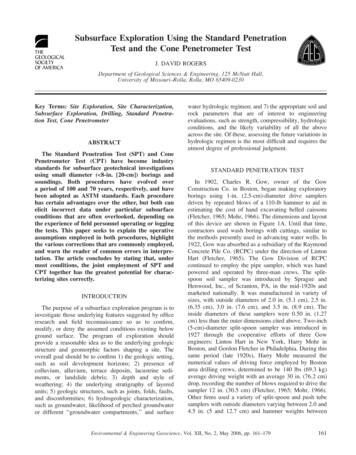
RogersFigure 1. (A, left). The original Gow pipe sampler was the first dry sampling method. It utilized 1-in. (2.5-cm)-diameter pipe drill rod with a recessedcoupling attached to a 1-in.-diameter pipe with a beveled cutting tip. (B, right) The components of a 2-in. (5.1-cm)-diameter Standard PenetrationTest (SPT) split-spoon sampler, developed around 1927, after the Charles R. Gow Co. had been absorbed by the Raymond Concrete Pile Company.Figures taken from Hvorslev (1949).100 and 350 lbs (45.5 and 159 kg) (Mohr, 1936, 1943;Stanton, 1936; and Acker, 1974).This modified Gow sampler recovered 13/8 in. (3.5-cm)diameter samples. Even though disturbed, drive sampleswere able to recover thin seams of material in the correctstratigraphic sequence, providing important details thatwash borings could not. Improvements to the samplebarrel were made over the years, including the introduction of a ball check valve to prevent sample loss.In 1945, the split-spoon sampler barrel was augmented bythe introduction of size A hollow drill rods (wall thicknessof 0.234 in. [0.59 cm]), which were equipped with Jackbitthreads (coarse flat threads, without deep or sharpundercuts). These replaced the old 1-in. extra pipe thathad been used until that time (Fletcher, 1965). By 1940,the Gow split-spoon sampler essentially appeared as weknow it today but accommodated only a 12-in. (30.5-cm)long sample, as shown in Figure 1B. During the early1621940s, RCPC lengthened their sampler to accommodate22 in. (55.9 cm) of sample, and this apparatus becameknown as Raymond Sampler (Hvorslev, 1949). In 1954,James D. Parsons of Moran, Proctor, Freeman, andMueser in New York introduced the conventionalprocedure wherein blows are recorded for each of three6-in. (15.2-cm) increments (Fletcher, 1965). The valuerecorded for the first round of advance is usually discardedbecause of fall-in and contamination in the borehole(Lo Pinto, 1966). The second pair of numbers are thencombined and reported as a single value for the last 12 in.(30.5 cm). This value is reported as the raw (uncorrected)Standard Penetration Test (SPT) blow-count value, commonly termed N or, more recently, as NSPT.Karl Terzaghi liked the Raymond Sampler becauseHarry Mohr had collected more than 30 years of subsurface penetration data around Boston, and since1927, Raymond had been employing the standardizedEnvironmental & Engineering Geoscience, Vol. XII, No. 2, May 2006, pp. 161–179
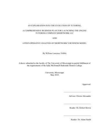
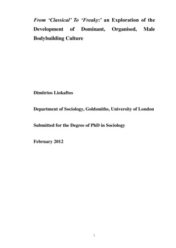
Subsurface Exploration Using the SPT and CPTTable 1. Prior to the introduction of energy corrections for depth,uncorrected blow counts, NSPT, were compared with charts like thosereproduced here, from Peck et al. (1953). These correlations wereused in classifying soils and used to determine allowable bearingcapacity and friction parameters for soils.Relative DensityTable 2. Estimated values of soil friction and cohesion based onuncorrected Standard Penetration Test (SPT) blow counts, takenfrom Karol (1960). Although bereft of overburden corrections, thesesimple correlations were generally used for shallow foundationinvestigations.Undisturbed SoilConsistencySands andGravelsBlows/Ft(NSPT)Silts andClayStrength(tsf)Blows/Ft(NSPT)Very looseLooseMediumDenseVery dense0–44–1010–3030–50Over 50Very softSoftFirmStiffVery stiffHard0–¼¼–½½–11–22–4Over 40–22–44–88–1616–32Over 32penetration procedure and apparatus out of all theiroffices across the United States. Terzaghi and ProfessorArthur Casagrande of Harvard University vigorouslysponsored adoption of the split-spoon sampling procedure through the auspices of the Committee onSampling and Testing of the Soil Mechanics andFoundations Division of ASCE, which was formed in1938. The work of this committee was carried out atHarvard by Juul Hvorslev, a former doctoral student ofTerzaghi’s in Vienna. Subsurface sampling procedureswere more or less standardized by 1940, when Hvorslev(1940) wrote ‘‘The Present Status of the Art of ObtainingUndisturbed Samples of Soils,’’ included as an 88-pageappendix to the Purdue Conference on Soil Mechanicsand Its Applications.Terzaghi realized that the penetration resistance of thesplit-spoon sampler could provide useful in situ test datathat might be correlated with the consistency and densityof the soils encountered. While he was writing the text ofSoil Mechanics in Engineering Practice, he sat downwith Harry Mohr and developed correlations between thenumber of blows, N, and a number of salient propertiesof soils, including the relative density of sands, consistency and unconfined compressive strength of clays, andallowable bearing pressure on sands and clays. In 1947,Terzaghi christened the Raymond Sampler procedure asthe ‘‘Standard Penetration Test’’ (SPT) in a presentationtitled ‘‘Recent Trends in Subsoil Exploration,’’ whichhe gave at the 7th Conference on Soil Mechanics andFoundation Engineering at the University of Texas atAustin. The first published SPT correlations appeared inTerzaghi and Peck (1948). These were soon followed bycorrelations relating SPT blow counts to consistency forsilts and clays and relative density for sands in Peck et al.(1953), who noted that the data for sands were morereliable than those for silts or clays. These classificationcharts are shown in Table 1. The SPT procedure and itssimple correlations quickly became soil classificationstandards across the United States. By 1960, publishedSoil Type andSPT Blow CountsCohesive soilsVery softSoftFirmStiffVery ohesionless te soilsLoose(,10)Medium(10–30)Dense(.30)Cohesion (psf)Friction Angle �1212charts were appearing that also estimated soil strengthbased on SPT blow counts, presented in Table 2.The ‘‘standard drive sampler’’ test was subsequentlyadopted by ASCE and the Corps of Engineers. In theearly 1950s, Sprague and Henwood began producingan 18-in. (45.7-cm) version of the 22-in. (55.9-cm)Raymond Sampler, and the barrel length was left openended (between 18 and 30 in. [45.7 and 76.2 cm]) whenthe SPT was adopted as ASTM Standard D 1586-84 in1958 (Figure 2). Since this time, it has more or lessbecome a nationwide standard. Despite standardizedbarrel dimensions, SPT samplers still employ an array ofcutting shoes with varying tapers and lip widths, shown inFigure 3. Variations on the SPT procedure have beenadopted by many foreign countries, and the InternationalReference Test Procedure for the SPT was adopted by theInternational Society for Soil Mechanics and FoundationEngineering in 1988. Figure 4 shows an SPT samplerbeing disassembled (left) and the opposing hemispheresof the split-spoon sampler open, exposing the recoveredsoil (right).Disadvantages of the SPT ProcedureThe SPT procedure evolved out of the Boston area,where Charles Gow used it to probe conditions preparatory to constructing his Gow Caissons, as was customelsewhere (Mohr, 1964). The procedure is most reliable ingranular soils, such as sand and granule gravel. A majorshortcoming with the SPT has been that silts and claysexhibit different driving resistances when dry or moist. IfEnvironmental & Engineering Geoscience, Vol. XII, No. 2, May 2006, pp. 161–179163
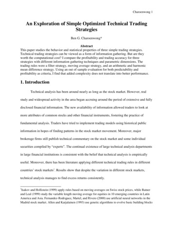
RogersFigure 2. Standard dimensions for the Standard Penetration Test (SPT) sampler, as given in ASTM D 1586-84.these materials become more moist at a later date, theymay not exhibit the stiffness predicted by the SPT.Another common source of interpretive error in theSPT procedure is when the sampler encounters rocksslightly larger than the sample barrel’s sleeve diameter, assketched in Figure 5. In these cases, very high blow countscan be recorded, and these horizons can easily be misinterpreted to be ‘‘bedrock’’ or ‘‘drilling refusal’’ when, infact, the object may be a ‘‘floater’’ within the colluvium(Figure 5). Seasoned operators usually take their boringsa good 10 ft (3 m) into supposed ‘‘rock’’ to be sure ofthe interpretation, usually through drilling resistance, notaccording to drive sampling resistance alone.A less recognized problem is the influence of stratathickness and changes in stiffness, sketched in Figure 6.As the sample barrel approaches an appreciably stifferhorizon, the penetration resistance will increase, eventhough the sampled material remains more or less constant throughout the softer horizon. This can lead tooverestimates of strength, density, and compressibilityFigure 3. Drive samplers usually employ three types of cutting heads, or shoes, shown here. The sharp tapered heads are intended for soil sampling,while the more blunt tips are designed for greater longevity when sampling granular soils.164Environmental & Engineering Geoscience, Vol. XII, No. 2, May 2006, pp. 161–179
Subsurface Exploration Using the SPT and CPTFigure 4. A split-spoon sampler barrel must be recovered from the hole, detached from the drill rod, and mechanically broken down, as shown at left.The two halves of a typical Standard Penetration Test (SPT) sampler with entrained soil are shown at right.based solely on blow-count values. A big disadvantage ofthe SPT procedure is that it reports the average blows perfoot during any given sample round, so the measurementwould only be valid for horizons .12 in. (30.5 cm) thick,plus the influence area beneath the sampler shoe sketchedin Figure 6. This is the zone of influence in front of thesampler shoe (sketched in Figure 6). This influence zoneusually encompasses an additional 8–14 in. (20–36 cm),equal to four to se
(5-cm)-diameter split-spoon sampler was introduced in 1927 through the cooperative efforts of three Gow engineers: Linton Hart in New York, Harry Mohr in Boston, and Gordon Fletcher in Philadelphia. During this same period (late 1920s), Harry Mohr measured the numerical values of driving force employed by Boston