Transcription
TutorialSSD / SOFiPLUS - A Quick ReferenceSSD Version 2010SOFiPLUS(-X) Version 2010 SOFiSTiK AG 2010
This manual is protected by copyright laws. No part of it may be translated, copied orreproduced, in any form or by any means, without written permission from SOFiSTiK AG.SOFiSTiK reserves the right to modify or to release new editions of this manual.The manual and the program have been thoroughly checked for errors. However, SOFiSTiKdoes not claim that either one is completely error free. Errors and omissions are corrected assoon as they are detected.The user of the program is solely responsible for the applications. We strongly encourage theuser to test the correctness of all calculations at least by random sampling.
Tutorial SSD / SOFiPLUS - A Quick ReferenceContents1SSD Basic Features.11.1Program Structure .11.2Program Version Matrix .11.3User Interface SSD.21.4Basic Workflow .31.4.1Groups.31.4.2Tasks .41.4.3Template Files name.SOFiSTiX.61.52Structure and Function Mode.91.5.1Computation Status .91.5.2SOFiSTiK Options.91.5.3File Types .11SOFiPLUS(-X) Basic Features.122.1General Principles for System Generation .122.2Mesh Generation based on Structural Elements .122.3Structural Elements – General Features .122.4Additional Command for structural Areas.142.4.1Wall.142.4.2Edit Area Edge Properties.142.4.3Boolean: Add Areas .142.4.4Bollean: Subtract.152.4.5Additional Point on Area Edges.152.4.6Remove Point from Area Edge.162.5Navigation inside SOFiPLUS(-X) .162.6Create Structural Areas with Option „Pick Point in Area“.172.7AutoCAD Grips for Structural Elements .172.8Mesh Options for Structural Lines.182.9New Table Elements.192.10Loads.192.10.1New Register Cards for Structural Elements .192.10.2Apply Free Loads to multiple Load cases.202.10.3Apply Free Loads to multiple Element Groups .202.10.4Loadcase Browser .202.11Named Selections and Groups .21Inhaltsverzeichnisi
Tutorial SSD / SOFiPLUS - A Quick Reference3Example Simple Slab .233.1General.233.2Step 1: Start SSD .233.3Step 2: Materials and Cross Section .253.4Step 3: SOFiPLUS(-X) – graphical Preprocessing .273.5Step 4: Create Structural Areas .283.6Step 5: Creating Supports and Downstand Beam .313.7Step 6: System Checks.333.8Step 7: Create Columns in Area(2) .333.9Step 8: Check of Combinations.343.10Step 9: Linear Analysis and Superpositioning .353.11Step 10: Design .393.11.1Design Parameters of Area Elements .393.11.2Design ULS.413.11.3Design SLS.433.124Step 11: Documentation .453.12.1Ausgabedokument mit URUSLA .453.12.2Insert additional Graphics.47Additional Help / Support.484.1Infoportal.484.2CADINP Samples .494.3User Group .494.4SOFiSTiK Program Manuals.504.5SOFiSTiK Support .504.5.1Support Accessibility.504.5.2Customer’s Obligation to Cooperate .514.5.3Support Requests via SOFiSTiK Online Protal.514.5.4Support Requests out of SSD / TEDDY .524.5.5Create a diagnostic.xml File.53Inhaltsverzeichnisii
Tutorial SSD / SOFiPLUS - A Quick Reference11.1SSD Basic FeaturesProgram StructureFigure 1: SOFiSTiK FEA Program Structure1.2Program Version MatrixThe following table shows the program versions FEA and SOFiPLUs(-X) related to operatingsystem and AutoCAD version.Tabelle 1: Program Version MatrixSSD Basic Features1
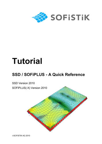
Tutorial SSD / SOFiPLUS - A Quick Reference1.3User Interface SSDIn order to understand the operation of the SOFiSTiK programs, the basic program structureis represented subsequently. It is imperative, that all data is stored in a central data base(SOFiSTiK Database CDB).The SOFiSTiK software has a modular structure. The SOFiSTiK Structural Desktop (SSD)controls the communication between all of the individual application programs.The SOFiSTiK Structural Desktop (SSD) represents a uniform user interface for the totalrange of SOFiSTiK software. The module controls pre processing, processing and postprocessing. The system can be entered graphically with SOFiPLUS(-X) or as parameterisedtext input using TEDDY. The control of the calculation and design process takes place usingdialog boxes, which are accessed via the task tree.The screen is divided into three main areas.1. task tree2. table area3. work areaFigure 2: SOFiSTiK Structural Desktop (SSD)SSD Basic Features2
Tutorial SSD / SOFiPLUS - A Quick Reference1.4Basic WorkflowThe SSD is task oriented. The tasks are arranged in groups (e.g. the group "System andload" contains the tasks materials, cross sections, geometry and loads).When creating a new project, the necessary groups and tasks are set by default dependingon the chosen problem.The sequence of the task are very important for the project calculation.1.4.1GroupsThe computational groups are organized in a tree-structure. This structure can be changedby the user at any time, as the individual tasks can be dragged to the desired place with themouse. The user can remove or insert additional groups at any time with associated tasks.Please use the right mous click menu inside the task tree window.This is an example of a standard group structe of astandard SSD project.:System-Model and loadingLinear Analysis-Linear analysis and superpositioningDesign Area Elements-Design ULS and SLSFigure 3: Navigation Window – Task TreeSSD Basic Features3
Tutorial SSD / SOFiPLUS - A Quick Reference1.4.2TasksThe tasks available are accessed via the right-click-menu in the task tree. They can beinserted at any place within the tree. When you select the command “insert task” with theright mouse-button, the following dialog with all available tasks appears.Figure 4: List of all available tasksSSD Basic Features4
Tutorial SSD / SOFiPLUS - A Quick Reference1.4.2.1 Task TreeIn the task tree the options are accessed via the right-click-menu which automatically adjustsitself to show only those available.Right click menu in the task treeThe right click menu will providerelevant functions for the selected task.Examples:ProcessEdità Dialogà Text-Input( name .DAT)Reportsà Result viewer( name .PLB)Figure 5: Right Mouse Click – Task Tree1.4.2.2 Table AreaDatabase information is written inthe table area.Possible categories:§ Geometry§ Loads§ ResultsThese results can be copied withright clicking menu into the clipboardPossible format:§ Text - Format§ EXCEL- FormatSSD Basic Features5
Tutorial SSD / SOFiPLUS - A Quick ReferenceFigure 6: Table Area1.4.2.3 Work AreaThe work area displays the ANIMATOR visualisation of the system by default. The work areachanges to WinPS during processing to show calculation status and the TEDDY for furthertext input prior to analysis. The graphical input with SOFiPLUS(-X) operates within its ownseparate window, making the best possible use of dual monitors.1.4.3Template Files name.SOFiSTiXFor processing of frequently recurrent standard tasks, the Template files of the type name .SOFiSTiX are provided. General Templates are saved in a subdirectory of theSOFiSTiK program directory, for example in:C:\Programs\SOFiSTiK\SOFiSTiK.23\ SSD-Templates.1.4.3.1 Adding User- defined Template directoriesFor own Templates, the user can define further Template-directories. SOFiSTiK à Options à SSD-Template Path à (Find-Button) and AddSuchen2.icoIn this directory, further subdirectories can be created. These subdirectories appear as tabsand template icons (see Figure 9). There is only one level of subdirectories available.Figure 7: SOFiSTiK à User Options à SSD-Template-PathSSD Basic Features6
Tutorial SSD / SOFiPLUS - A Quick Reference1.4.3.2 User Defined Template FilesAny file name .SOFiSTiK can be stored into the desired Template-Directory as Template name .SOFiSTiX.All current project settings can be saved as Templates Including the arrangementand sequence of the tasks. The materials and cross sections are dependent onthe chosen design code. A fixed design code cannot be changed within theproject. File à Save As TemplateFigure 8: Dialog Save Project as TemplateA later changing of the code is possible if the Template is stored “withoutdesign code".The existing Template directoriesare shown under Directories.Figure 9: File à save project as templateThe saved file name .SOFiSTiX is now available as a further Template.SSD Basic Features7
Tutorial SSD / SOFiPLUS - A Quick Reference1.4.3.3 Usage of Template Files name .SOFiSTiX file à New Project from Template The following templates out of the template path are availableRoot ��CABD““pretee”Figure 10: File à New Project from Template .The desired file name .SOFiSTiX is selected and stored under a new data file name withthe button “Save As ” into a project directory.The new file contains all tasks of the Template. In addition, the data (for example crosssections, geometry. etc.) from the Template are transferred into the new file. The data isthen immediately ready for calculation.With "Templates without Design Code”, the design code can be altered. Thematerials and cross sections must be checked and amended.SSD Basic Features8
Tutorial SSD / SOFiPLUS - A Quick Reference1.5Structure and Function Mode1.5.1Computation StatusEvery task has its own symbol to show the actual computation status.Without computationInput is written directly into the databaseGreen check markNo computation requiredBlue arrowNew input data à computation requiredBlue crossOld data à computation requiredRed crossError message à computation requiredGreen crossWarning message à computation required (possibly)Figure 11: Computation Status1.5.2SOFiSTiK OptionsNumerous settings within the options dialog are possible of which only the most importantare introduced now.The user may set the different options in:SOFiSTiK à User Options SOFiSTiK à Global Options SOFiSTiK à Project Options For further explanation please see the SOFiSTiK 1.pdf user manual.SSD Basic Features9
Tutorial SSD / SOFiPLUS - A Quick Reference1.5.2.1 Language SettingsThere is a difference between the dialog box language and the input/output language.For these settings two different dialogues will be used.With the SSD menu SOFiSTiK à User Options à SOFiSTiK General à DialogueLanguage you may change the general language of all SOFiSTiK dialogues only. To changethe output language please use the command form SSD menuSOFiSTiK à Global Options à SOFiSTiK General à Language.For chanigng the output language you also may use the commandSOFiSTiK à Project Options à SOFiSTiK General à LanguageProject settings will be saved in a file called SOFiSTiK.def in your project directory. Globalsetiings will be saved in your program directory and will affect all following projects.Figure 12: SOFiSTiK: Options àDialogue Language1.5.2.2 Project DefaultsWith the option Project Defaults, the user can assign default attributes of new projects. Inaddition to that, the user can also define the type of Preprocessing graphically withSOFiPLUS or text based with TEDDY. These attitudes are stored in the Registry.SSD Basic Features10
Tutorial SSD / SOFiPLUS - A Quick ReferenceFigure 13: SOFiSTiK: Options à Project Defaults1.5.3File TypesAll type of files used by the SOFiSTiK software are listed in the table below.:Name.SOFiSTiKCentral XLM- file where all information is saved.Name.DATControl file, ASCII formatName.PLBFor each task the result is saved in a file task.PLB. This file can beshown and/or printed out individually. Also it can be assigned to thetotal result using the command "all results".Name.CDBCentral data baseName.DWGUsing graphical input all information about system and loading issaved in this drawing.Name.SOFiSTiXTemplate- file in XLM- format: File in Template- directory.Table 2: Overview of the file- ExtensionsTo open and recalculate a project without graphical input only the filename.SOFISTIK is sufficient.For a project with graphical input the files name.SOFiSTiK and name.DWG arenecessary.SSD Basic Features11
Tutorial SSD / SOFiPLUS - A Quick Reference22.1SOFiPLUS(-X) Basic FeaturesGeneral Principles for System GenerationThe graphical preprocessing with SOFiPLUS(-X) is based on AutoCAD or ADT.There are two general principles for system generation:Using structural elements using finite elementsUsing structural elements is the most common way to define the model geometry. With thestructural elements you will simply model your structure as a wireframe model, whichcontains points, lines and areas. With the export command an automatic mesh generationwill be started in the background.The classical way for system generation can be used by directly drawing the necessary finiteelements in the SOFiPLUS environment. In this case you must define every element type likenodes, beams, springs, etc. directly.For further help, please see the help files in SOFiPLUS.2.2Mesh Generation based on Structural ElementsWith the basic objects area, line and point you will simply draw a wireframe model inSOFiPlUS(-X). With the „Export .dwg- .cdb “ command the automatic mesh generation willstart in the background. In a first step the mesh generator will create all necessarydependencies and intersections. Based on this additional information the final finite elementmesh will be generated. The mesh can be checked with the ANIMATOR.2.3Structural Elements – General FeaturesFor system modelling three basic structural elements are available: area, line and point.Additional elements like walls and openings are derived from the basic elements.All elements are independent from each other. For example copying and movingelements are possible with the normal AutoCAD commands.SOFiPLUS(-X) Basic Features12
Tutorial SSD / SOFiPLUS - A Quick ReferenceThe following list describes the most important properties of every basic element.Structural area ( SAR in PROG SOFiMSHC)plate, wall, shell and membrane elementswalls and openings are derived from this elementStructural line ( SLN in PROG SOFiMSHC)-geometric boundary for mesh generationBeam elementTruss elementCable elementPile elementBoundary elementLinear support and/or kinematic couplinggeometry: line, curve or spline geometry possibleStructural Point ( SPT in PROG SOFiMSHC)--geometric point for mesh generationsupport conditionColumn with dimension for punching designSpring elementHalf space pileVery important is the new feature, that the mesh generator automatically calculates theintersections. This is very helpful feature mainly in 3d system generation.Figure 14: Intersection of two structural areas in 3d environmentSOFiPLUS(-X) Basic Features13
Tutorial SSD / SOFiPLUS - A Quick Reference2.4Additional Command for structural Areas2.4.1WallThis little feature creates automatically vertical structural areas walls based on horizontallines. The height of this area can be defined in an edit box, which is located inside thesidebar on the left side of your desktop. (Please see also chapter 2.5) You may also use thefeature „pick point in area“. In this case the boundary elements of the area will be foundautomatically and walls will be created. In the sidebar an additional option regarding theboundary options is available now. In this case openings will be detected automatically whilecreating walls. (See picture below)The value fort he wall height (see sidebar) is only a help while creating walls.2.4.2Edit Area Edge PropertiesThe properties of edges are related to the arera. Nevertheless with this new commandyou may select several edges from different areas andchange properties2.4.3Boolean: Add AreasWorking with structural elements some useful tools are now available. In case you like tomerge two areas the command „Boolean: Add“ will do this in a very simple way. Theproperties of the area you clock first will be used for the new merged areaSOFiPLUS(-X) Basic Features14
Tutorial SSD / SOFiPLUS - A Quick Reference2.4.4Boolean: SubtractOn the other side it is also possible to subtract areas.2.4.5Additional Point on Area EdgesIn case it is necessary to change the geometry of anarea, simply add a new point to the area edges. Aftercreating new points on area edge new AutoCAD gripsare available. Simply use this new grips to change thearea geometry.SOFiPLUS(-X) Basic Features15
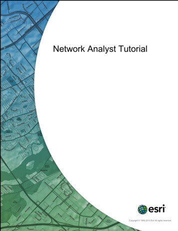
Tutorial SSD / SOFiPLUS - A Quick ReferenceFor very grip point a finite element node will be generated.Original Area2.4.6Add pointsMove grips for new geometryRemove Point from Area EdgePlease use the command „Remove Point from Area Edge“ to remove points.2.5Navigation inside SOFiPLUS(-X)Normally you will use the SOFiPLUS(-X) toolboxes located inside the AutoCAD Menu. A newfeature is our Sidebar, which contains all necessary commandsFigure 15: Desktop SOFiPLUS(-X) with SIDEBARSOFiPLUS(-X) Basic Features16
Tutorial SSD / SOFiPLUS - A Quick ReferenceInside the Sidebar you will find a register card called „Log“. In case of warnings, errormessages or additional information you will find everything listed in this register card.2.6Create Structural Areas with Option „Pick Point in Area“When creating an area with the option „Pick Point in Area“ additional options area availabelin the Sidebar. Using the option „Detect Boundary“ will automatically detect all openings inyour area.The two options are:Single boundaryCreates an area with all boundary elementsDetect openingsArea and openings will be created automatically2.7AutoCAD Grips for Structural ElementsAll structural elements contain the original functions of the AutoCAD grips. To changegeometry simply use the grips to do so.Figure 16: Structural area with gripsSOFiPLUS(-X) Basic Features17
Tutorial SSD / SOFiPLUS - A Quick Reference2.8Mesh Options for Structural LinesInside the dialog “Structural Line” register card “Beam/Cable” there are different meshingoptions available.Figure 17: Dialog Structural LineMesh AutomaticallyThe mesh generator creates single elemts whichare connected to the overall meshCreate ElementsThe mesh generator creates single elemts whichare not connected to the overall meshCreate One Element withoutSectionsThis options creates one single element, whichis not connected to the overall mesh. Normallyused for cable elements.Create One Element with SectionsThis options creates one single element withbeam sections, which is not connected to theoverall mesh. Normally used for cable elements.Intersect With Other ElementsIn case this option is not selected, nointersection between elements will be used. Alsostart and end point of the line will be notconnected to the overall mesh. For aconnections an additional structural point isnecessary.SOFiPLUS(-X) Basic Features18
Tutorial SSD / SOFiPLUS - A Quick Reference2.9New Table ElementsTo define Bedding and/or constraints new table elements are available in the input dialog. Allnecessary input will be done in this table. Using thebutton to create a new line with therelevant input. In case one or more table line are marked and you use theyou will get a copy of the marked lines. With thebutton againbutton you may delete the marked lines.When defining new constraints you will be able to select elements directly out of yourdrawing. (Please note: this function is only available when defining couplings for nodes)Figure 18: Register Card Constraints – Table of couplings2.10Loads2.10.1New Register Cards for Structural ElementsAll structural elements contain a new register card “Loads”. With this register card it is nowpossible to define and modify loads directly connected to the elements.Please create all necessary loads at first inside the loadcase manager. There isno automatic update inside the loadcase manager for all load cases defined inthe element register cards.SOFiPLUS(-X) Basic Features19
Tutorial SSD / SOFiPLUS - A Quick ReferenceFigure 19: Register card „Loads“2.10.2Apply Free Loads to multiple Load casesAnother new feature is the possibility to apply free loads to more than one load case. Simplyinput the load case numbers divided by an comma2.10.3Apply Free Loads to multiple Element GroupsUsing frre loads you are able to apply these loads to more than one group or element. Simplyinsert all group/element numbers divided by a comma.2.10.4Loadcase BrowserWith the new loadcase browser is is easily possible to navigate through all available loadsand switch on/off the visibility. Changes are directly visible inside the drawing.When starting the loadcase browser, all visible loads out of the drawing are ticked in theloadcase browser.SOFiPLUS(-X) Basic Features20
Tutorial SSD / SOFiPLUS - A Quick ReferenceFigure 20: Loadcase Browser2.11Named Selections and GroupsFor a better overview of your project you may use the command “Display Selection Set only”.With this command only the selected elements are visible on your screen. Now it is possibleto save this selection for a later recall. With a right mouse click in your screen you can selectthe command “Named Selections Save as new Selection ”.In case named selections are saved in the drawing, use the right mouse click and thecommand “Named Selections Restore ‘name of selection’” to recall the selection.Please use the command “Display Selection Set only” and select the elements foryour named selection before saving it.SOFiPLUS(-X) Basic Features21
Tutorial SSD / SOFiPLUS - A Quick ReferenceFigure 21: screenshot with command “Named Selection”SOFiPLUS(-X) Basic Features22
Tutorial SSD / SOFiPLUS - A Quick Reference3Example Simple SlabFigure 22: Drawing of simple slab with downstand beam3.1GeneralThis small example shows the basic workflow of the SSD and SOFiPLUS(-X) on a simpleslab. After working through this example the user should be able to work on small projects,starting with the graphical system and load generation and ending up with analysis, designand documentation. For this reason there will be no detailed discussion and explanationregarding the design. A basic knowledge in using AutoCAD, TEDDY and ANIMATOR areobligatory.This tutorialFor further information and help please see also chapter 4.3.2Step 1: Start SSDFirst of all start the SSD with a double click on thebutton. Now you will see the maindesktop.To start a new project please click on the / button or go to the menu “File New Project ”.Now the following dialog appears. Please insert a project title, the name of your databaseand the project directory.Example Simple Slab23
Tutorial SSD / SOFiPLUS - A Quick ReferenceFigure 23: Dialog System InformationFor system generation we like to use SOFiPLUS(-X). Therefore please select this option inthe area “Preprocessing”. Please use the default settings in this dialog and confirm with theOK button. Now the files “slab-01.cdb” for the database, “slab-01.dwg” for the SOFiPLUS(-X)drawing and “slab-01.sofistik” for project file will be generated.Example Simple Slab24
Tutorial SSD / SOFiPLUS - A Quick ReferenceThe selection o the design code cannot be changed after leaving the dialog.Figure 24: General view of SSD with new projectAs described in chapter 1.4.2.1 you will find the task tree on the right side of your screen. Forcompleting the project you simply have to go through all tasks starting at the top of the tree.3.3Step 2: Materials and Cross SectionAs a default setting four materials are predefined. Concrete C 20/25, reinforcement steel BSt500 SA, construction stele S 235 and masonry MZ4 I. For editing the material propertiessimply unse the right mouse click on any material and material dialog appears. In this dialogyou may change easily the properties, for example concrete from C 20/25 up to C 30/37.Confirm the new properties with the OK button.Example Simple Slab25
Tutorial SSD / SOFiPLUS - A Quick ReferenceFigure 25: Dialog MaterialTo delete a material simply click on the material and delete it with the DEL key. Alternativelyuse the right mouse click and the command “delete”.For the downstand beam we need a specific cross section. To define a new material pleaseuse again the right mouse click on the task “Cross Sections” and select the command “New”.Out of the upcoming dialog select a “T-Beam section” for further input.Figure 26: List of cross section typesExample Simple Slab26
Tutorial SSD / SOFiPLUS - A Quick ReferenceFigure 27: Input dialog T-Beam sectionInside this dialog simply define all necessary data for your cross section. For furtherinformation regarding the position of origin and the theoretical background of T-Beamsplease see or ASE manual, chapter 2.3.1 SOFiSTiK – T-Beam Philosophy.3.4Step 3: SOFiPLUS(-X) – graphical PreprocessingNow we start the graphical system generation. Open SOFiPLUS(-X) with a double click onthe task “GUI for Model Creation”. We recommend preparing the basic geometry with anAutoCAD drawing.In most cases it is very helpful to make a sketch with all necessary geometricinformation. This sketch also shows where necessary simplifications should beused.Example Simple Slab27
Tutorial SSD / SOFiPLUS - A Quick ReferenceThe basic geometric structure of this example can be easil
Tutorial SSD / SOFiPLUS - A Quick Reference SSD Basic Features 1 1 SSD Basic Features 1.1 Program Structure Figure 1: SOFiSTiK FEA Program Structure 1.2 Program Version Matrix The following table shows the program versions FEA and SOFiPLUs(-X) related to operating system and AutoCAD version. Tabelle 1: Program Version Matrix


![Database Management System [DBMS] Tutorial](/img/2/dbms-tutorial.jpg)