Transcription
Towards Adaptive Kinetic-FluidSimulations ofWeakly Ionized PlasmasVladimir Kolobov and Robert ArslanbekovSemicon WestSan Francisco, CAJuly 14, 2011
Agenda Plasma Technologies and Plasma Models Commercial Software for Plasma Simulations Simulations of industrial plasma reactors forsemiconductor manufacturing with CFD-ACE Evolution of Mesh Technologies: from Body-Fitted toCartesian Mesh Adaptive Mesh Refinement (AMR) using OctreeCartesian mesh Unified Flow Solver and AMAR technology for multiscale kinetic-fliud simulations of gas flows in thetransitional regimes Plasma Simulations with AMR Conclusions
Plasma Technologies Thrusters"The XXI century will be not only the century ofinformatics, biology and space exploration, but alsothe century of plasma technologies" A.I.Morozov 2006 Lighting Spray Coatings Materials Processing Displays
Plasma ModelsDifferent plasma models are currently used for modeling thermal andnon-equilibrium plasmasHigh PressureThermal Plasmas Te T, LTE Gas Flow (turbulence) Heat Transfer Radiation (HF EMAG) Non – Equilibrium Chemistry Two Temperature Te TKey Features Radiation Transport Gas Heating T TroomLow PressureNon-EquilibriumPlasmas Magnetic Field Effects Kinetics of Ions & Fast Neutrals Kinetics of Electrons Non-Local ElectrodynamicsThe need to develop new modeling techniques that address vastly differentscales having different physics at both low and high pressures speaks to theconvergence of the discipline
Commercial Software forPlasma SimulationsCFDRC developed the first commercial tool for plasma simulationsIn 2004, CFD-ACE software was sold to ESI group.
Plasma Simulations with CFD-ACE 2D Cartesian orCylindrical3D Cartesian1D Positivecolumn0D Well stirredGlobalPlasma ModelNon - EquilibriumFlowHeatChemistryMagneticLocal Thermodynamic Equilibrium GlobalRadiationMagneticTurbulenceUser SubroutineReaction ManagerArrh. RateCross-SectionsMaxw EEDFNon-Maxw EEDFDashed lines indicate anoptional or alternative choice
Inductively Coupled Plasma Reactors
Capacitively Coupled Plasma Reactor Multi-frequencyelectrodes Coupled plasmaand gas dynamicssimulations External Circuitmodels Complex gas andsurface chemistry ParallelCapabilities
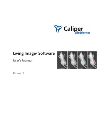
Electron KineticsCalculated electron temperature (left) and electrostaticpotential (right) for Ar ICP at 10 mT, 6.8 MHz, 100W. f 0 v1 2 eE div(f1 ) 2 f1 S0 v t 33v v m EEPFs at different points along the discharge axis at radial position r 4cm: a) measured, b) calculated. f1eE f 0 f1 v f 0 tm vTwo-term SHE reduces 6D Boltzmann equation to a 4D Fokker-Planck equation for electrons invcollisional plasmasf (r, v.t ) f 0 (r, v,t ) f1 (r, v, t ) f 0 f 0v Dr f 0 t t Using total energy (kinetic potential) simplifies analysis1 f 0 D(r, ) V(r, )f 0 of electron kinetics for many gas discharge problems S V. Kolobov & R. Arslanbekov, Simulation of Electron Kinetics in Gas Discharges, IEEE TPS 34 (2006), 895
Pattern Formation in DBDOur simulations: fluid model with LUTsExperimental measurements of pattern formationdynamics in He DBD 200kHz, 30kPa, 690 V.Stollenwerk et al. Phys. Rev. Letters 96 (2006) 255001Open questions Effect of computational mesh Operating conditions (gas, pressure, voltage) Electrode resistivity
Summary about plasma simulations with CFD-ACE Panasonic Pantheon E800 Dry Etcher Performed simulations of numerousplasma reactors and processes forsemiconductor manufacturing, lighting andother applications Accumulated considerable experience indeveloping chemical reaction mechanisms: rare gases (lighting, PDP) O2, N2, Cl2, H2 Fluorocarbon plasmas (SF6, C2F6, .) SiH4 for deposition of SiO2 Hydrocarbon plasmas (DLC films, CNT,etc) Performed coupled reactor/feature scalesimulations using CFD-TOPO Developed concept of Virtual Plasma3D simulations of an industrial ICP reactor withcomparison to experimental data by V.Kolobov, K.Ikedaand T.OkumuraReactor for process optimization insemiconductor manufacturing
Evolution of Mesh Technologies Partial Differential Equations governing Plasma Dynamics are solved numericallyusing computational mesh From Body Fitted Mesh (Structured and Unstructured) to Adaptive CartesianMesh with Embedded BoundariesStructured body-fitted rectangular meshCombination of structured Cartesianmesh and hybrid unstructured body-fittedmesh near the wallUnstructured body-fitted meshStructured Cartesian mesh withembedded boundary
Comparison of Mesh Types Advantages ofbody-fitted meshes place nodes optimally to resolve geometrical features of the problem increase mesh density towards the wall Disadvantages ofbody-fitted meshes approximation errors caused by spread of inter-nodal distances (LTE) loss of robustness caused by skewed faces difficulties with automated mesh generation and adaptation Advantages of Cartesian meshes Local Truncation Error (LTE) minimization robustness of differencing scheme simplicity and robustness of mesh generation algorithm simplicity of navigation on mesh dynamic mesh adaptation multi-grid solvers Drawbacksof Cartesian meshes more complicated boundary treatment: cut cells versusImmersed Boundary Methods
The Future of CFDCFD and CAD companies are moving towardsCartesian mesh for automatic mesh generationCONVERGE employ a runtime gridgeneration technique for combustionsimulations Eliminates the user-time to generategrids - only the surface geometry issupplied to the CONVERGE solver. Allows moving boundaries to behandled completely automatically. Eliminates the deforming mesh issuestypically associated with movingboundaries. Allows for perfectly orthogonal cellsresulting in improved accuracy andsimplified numerics. Maintains the true geometry,independent of the mesh resolution.Therefore, the use of fixed embedding oradaptive mesh resolution on boundariesincreases the accuracy of the geometryrepresentation.
Open Source CFD: Gerris Flow Solver GFS is a free software for solving PDEs with AMR Import STL surface geometry from CAD Cut-cell methods to define BC Some moving boundary capabilities Fully Threaded Three for navigation on Mesh Multi-Grid Poisson Solver Poisson equation is solved using a relaxation operator Multilevel acceleration is used with a classical “V-cycle” Advection Tracer Solver Conservative formulation with Godunov scheme forthe advection term in the tracer solver The diffusion term is treated using the multigrid Poisson solver
Unified Flow SolverNext Generation Computational Tool forHigh-Altitude Aerothermodynamics andLow-Speed Micro-FlowsProblem Statement A large variety of flow problems are characterized by thepresence of continuum and rarefied flow domains Computational simulations to define and resolve physicalphenomena require appropriate models for both domains Direct Simulation Monte-Carlo (DSMC) methods producestatistical scatter so large compared to the small changes offlow quantities that meaningful results can not be obtainedCoupled Continuum and Rarefied FlowSolver Capable of Auto- SwitchingBased on Local Gradients of GasDensity, Flow Velocity, & TemperatureUFS ComponentsDirect SimulationMonte Carlo (DSMC)DomainDecompositionAdaptive Mesh & AlgorithmRefinement CouplingAlgorithmContinuum KineticSchemes Automatic generation ofCartesian mesh with embeddedsolid boundariesTree based adaptation of themesh to the solution andgeometryAutomatic switching based oncontinuum breakdown criteria Actively being developed with funding from U.S.Air Force, MDA, NASA, and U.S. NavyOur Solution UFS has been developed for simulations of rarefied, transitionaland continuum flows based on direct numerical solution of theBoltzmann equation coupled to kinetic schemes of gasdynamics Tree-based, dynamically adaptive mesh, and a local algorithmswitching strategy. Quad/Octree Cartesian Mesh is generated bysubsequent division of square boxes. The procedure of gridgeneration is represented by a tree Code developed for maximum computational efficiency, withhigh accuracy and numerical stabilityApplicationsKey Features BoltzmannEquationDirect NumericalSolution (DNS) Developed at CFDRC in 2003-2007 as a result ofsuccessful U.S. Air Force SBIR (TPOC EswarJosyula) Direct Numerical Solver (DNS) of theBoltzmann Equation is used in regions ofmoderate and high local Knudsen number,while kinetic schemes of gas dynamics areused elsewhereUFS is being applied to analyzeLunar soil debris transport fromLunar Lander rocket plumeimpingementFragment# 524Direct solver for BTE with different interactionpotentials Explicit solver for the kinetic Euler and NSequations Compact, flexible problem definition & caseset-up, with Spatially-varying boundary andinitial conditions through input fileHigh efficiency and numerical stabilityare attained by using similarcomputational techniques for kineticand continuum solvers, and byemploying an intelligent domaindecomposition algorithmUFS provides a push-button tool for generating adeterministic ensemble of steady-state and tumblingbody aerodynamic datasets of Missile Debris Fragmentsenabling more accurate probability of kill predictionsProvided ShapeSurface Pressure DistributionSurface geometry of theWaverider hypersonic glidevehicle and initial Cartesianmesh with 2M cellsUFS Simulationof the InflatableReentry VehicleExperiment withstream lines, Machnumber contours, andcomputational mesh.Modelled ShapeFully resolved Mach No. Contours
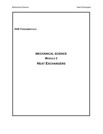
Illustration of UFS methodologyDynamic mesh adaptation to the solution and automatic selection offluid or kinetic solvers based on continuum breakdown criteriaFlow Around Cylinder for different Kn numbers: M 3, Tw 4Density ProfileMesh Refinement Criterion: 0.1Continuum Breakdown Criterion:222 p 1 u Kn 0.1 p T x y Cartesian Mesh with Cut Cell Embedded Boundary
Space Filling Curves for ParallelizationDomain decomposition using SFCIllustration ofDynamic LoadBalancing
Plasma Modeling with AMRMinimal Plasma ModelA simplest set of equations for the electronand ion densities, and Poisson equation forelectrostatic potential. ne div e ne t ni ne tElectron diffusion and ion transport areneglected e Ene E0 E 0 exp 4 ne ni Mesh Adaptation criteria nene 3 log10 (ne ) log10 ( ni ) log10 ( i ) log10 ( E ) max(n)max(n)ee 20 When gradient of exceeded a fixed valuethis particular cell was refined 1in a cell,When 1/ 4 in a cell, this cell was coarsenedThe procedure of mesh adaptation performed after several time steps
Streamer development in negative corona2D axi-symmetric simulation of streamer development near a needle-likeelliptic cathode and a flat anode: p 760 TorrA constant electron density 105 cm-3 is assumed at the cathode surface. The streamerpropagates with a velocity by an order of magnitude higher than the electron drift velocity .The calculated streamer velocity agrees with the classical estimate for the fast streamervelocity.The plasma channel is formed on the axis of the discharge.
Streamer development in positive corona2D axisymmetric simulations of positive corona dischargeAn off-axis toroidal channel was formed in our simulations.This behavior was observed with different physical models for differentelectrode shapes.The computational grid (left), electrostatic potential (center), and the electrondensity (right) for a streamer developing near a rod-shape anode.
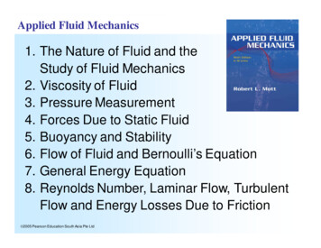
3D structures in positive corona3D simulations revealed that the 2D axi-symmetric channels break into separatestreamers. The streamers form near the anode with an almost periodic pattern andpropagate in slightly different directions with different speeds. Only two streamers survivedat a long distance from the anode. The code generates about 1.5 million cells duringparallel simulations on 8 cores.Computational grid, electron density contours at 107 cm -3, and the electric fieldstrength (color, maximum value 7 106 V/m ) at 15 ns (left) and 20 ns (right)
Extended Plasma Model A set of equations for the electron and iondensities, and Poisson equation forelectrostatic potential Ion transport is included Multiple species ions are allowed byintroducing species specific mass,diffusion coefficients, and ionization rates Local field approximation for ionizationrate Electron Energy Transport with accountfor electron thermal conductivity CANTERA link implementation isunderway for complex reactionmechanisms ne div e ne t e e Ene De ne 4 ne ni ni div( i ) ne t i i Eni Di ni E0 E 0 exp n S tn ne 55 e En De n 33
Classical DC Glow Discharge2D axi-symmetric simulationsThe model reproducesbasic structure ofclassical DC glowdischargesSpatial distribution of electron density with account of thermal conductivityAxial distributions of electron and ion densities (left), electrostatic potential andelectron temperature (right) with account of electron thermal conductivity
Discharges with Rod Shape Cathode15 Torr32 µAComputational grid and the electrostatic potential (left), and electron density contours(right) for a glow discharge between a rod cathode and a planar anode.Axial profiles of the electron and ion density (left), the electron temperature and the xcomponent of the electric field (zoom on the plasma region)
Cage DischargeSchematic of cage discharge and dischargecross section illustrating high-densityplasma generation process (right).Computational grid and electric potential andlog10(ne) (right) for a cage discharge
Conclusions & Future Plans 3D simulations of industrial plasma reactors can beroutinely done today using fluid models Adaptive Cartesian mesh has many advantages comparedto the traditional body-fitted mesh techniques We have developed a Unified Flow Solver using AMARtechnique for coupling kinetic and fluid solvers for gas flows We have shown that fluid plasma models can be extendedfor the adaptive Cartesian mesh and illustrated the benefitsof AMR for simulations of corona and streamer discharges The development of adaptive kinetic-fluid simulations ofplasmas is a subject of our current research
Acknowledgement Work supported by a NASA SBIR Project and AFOSRSTTR Projects. Further details can be found in Kolobov & Arslanbekov“Towards Adaptive Kinetic-Fluid Models of Weakly IonizedPlasmas”, Journal of Computational Physics,doi:10.1016/j.jcp.2011.05.036
Unified Flow Solver Problem Statement Our Solution A large variety of flow problems are characterized by the . Direct Simulation Monte-Carlo (DSMC) methods produce statistical scatter so large compared to the small changes of flow quantities that meaningful results can not be obtained UFS has been developed for simulations of rarefied .