Transcription
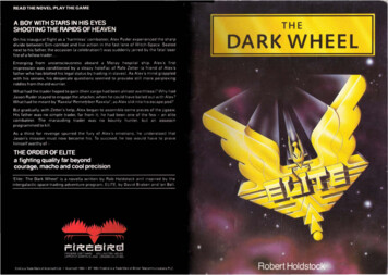
Review ofScientific InstrumentsARTICLEscitation.org/journal/rsiThe FIREBIRD-II CubeSat mission: Focusedinvestigations of relativistic electron burstintensity, range, and dynamicsCite as: Rev. Sci. Instrum. 91, 034503 (2020); doi: 10.1063/1.5137905Submitted: 13 November 2019 Accepted: 3 March 2020 Published Online: 19 March 2020A. T. Johnson,1,a)M. Shumko,1B. Griffith,1D. M. Klumpar,1 J. Sample,1223H. E. Spence,S. Smith,A. Crew,M. Handley,4K. M. Mashburn,45and J. B. BlakeL. Springer,1 N. Leh,1B. A. Larsen,4AFFILIATIONS1Physics Department, Montana State University, Bozeman, Montana 59717, USA2Physics Department, University of New Hampshire, Durham, New Hampshire 03824, USA3Applied Physics Laboratory, Johns Hopkins University, Laurel, Maryland 20723, USA4Los Alamos National Laboratory, Los Alamos, New Mexico 87545, USA5Space Science Applications Laboratory, The Aerospace Corporation, El Segundo, California 90245, USAa)Author to whom correspondence should be addressed: arlotjohnson@gmail.comABSTRACTFIREBIRD-II is a National Science Foundation funded CubeSat mission designed to study the scale size and energy spectrum of relativisticelectron microbursts. The mission consists of two identical 1.5 U CubeSats in a low earth polar orbit, each with two solid state detectors thatdiffer only in the size of their geometric factors and fields of view. Having two spacecraft in close orbit allows the scale size of microbursts to beinvestigated through the intra-spacecraft separation when microbursts are observed simultaneously on each unit. Each detector returns highcadence (10 s of ms) measurements of the electron population from 200 keV to 1 MeV across six energy channels. The energy channels wereselected to fill a gap in the observations of the Heavy Ion Large Telescope instrument on the Solar, Anomalous, and Magnetospheric ParticleExplorer. FIREBIRD-II has been in orbit for 5 years and continues to return high quality data. After the first month in orbit, the spacecraft hadseparated beyond the expected scale size of microbursts, so the focus has shifted toward conjunctions with other magnetospheric missions.FIREBIRD-II has addressed all of its primary science objectives, and its long lifetime and focus on conjunctions has enabled additionalscience beyond the scope of the original mission. This paper presents a brief history of the FIREBIRD mission’s science goals, followed by adescription of the instrument and spacecraft. The data products are then discussed along with some caveats necessary for proper use of thedata.Published under license by AIP Publishing. https://doi.org/10.1063/1.5137905., sI. SCIENCE OVERVIEWFIREBIRD is a pair of 1.5 U (10 10 15 cm ) CubeSats (Fig. 1)supported by the National Science Foundation (NSF) and designedto investigate the spatial scale and energy dependence of electronmicrobursts.1,2 Microbursts are short intensifications of electronprecipitation into the atmosphere lasting up to a few hundred milliseconds. An example of microbursts observed by Flight Unit 4 onDecember 23, 2016, is shown in Fig. 2. The term “microburst” wasfirst used by Anderson and Milton3 to describe enhancements inballoon observations of 100 keV bremsstrahlung x rays caused by3Rev. Sci. Instrum. 91, 034503 (2020); doi: 10.1063/1.5137905Published under license by AIP Publishingelectrons impacting the atmosphere. Later, balloon observations upto 300 keV revealed microbursts to be a significant loss process in thedayside magnetosphere.4 More recently, relativistic ( 1 MeV) electron microbursts have been observed in situ by spacecraft.5–7 Despitethe historical record of observations, much is still unknown aboutmicrobursts. FIREBIRD was designed to answer three outstandingquestions of microburst science:1.2.3.What is the spatial scale size of an individual microburst?What is the energy dependence of an individual microburst?How much total electron loss do microbursts produce globally?91, 034503-1
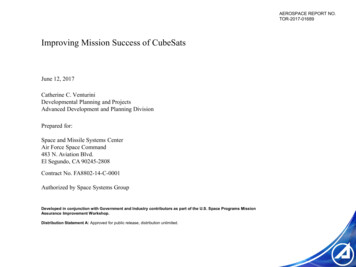
Review ofScientific InstrumentsFIG. 1. The FIREBIRD-II CubeSats fully assembled before delivery with Flight Unit4 in front. The top third of each flight unit contains the FIRE (FIREBIRD Instrumentfor Relativistic Electrons) instrument while the bottom two thirds contain the BIRD(Bus In support of Radiation Detector) spacecraft bus. The antenna can be seenwrapped around the gap between the two sections. The top of the spacecraft hasthe global positioning system (GPS) antenna (square seen to the lower right) andthe two detectors protected by dust covers removed before launch. The surfacedetector is under the square cover at the top right and the collimated detectorunder the circular cover to the bottom left.The spatial scale size of microbursts has been investigated sincetheir discovery and is an important factor toward understandingthe significance of microbursts as a loss process. Balloons flownby Parks8 measured bremsstrahlung x rays resulting from ion. The balloon payload consisted of four collimated xray detectors: one pointing at zenith with the other three at 30 fromzenith and 120 apart in azimuth. Parks8 estimated a microburstradius of 40 14 km; however, events were only considered whenseen by all four telescopes placing a minimum size on an event to beconsidered. Parks8 notes that most bursts were seen by at least twotelescopes, but many were only seen by the zenith telescope placinga maximum radius on those bursts of 20 km. Blake et al.6 found abouncing packet of microburst electrons on the Solar, Anomalous,and Magnetospheric Particle EXplorer (SAMPEX) Heavy Ion LargeTelescope (HILT) detector, which must have been “at least a fewtens of kilometers.” Blake et al.6 found few events where the entiredecay of a microburst could be observed and concluded that a typicalmicroburst has a scale size of less than a few tens of gyroradii, on theorder of a few kilometers. Dietrich et al.9 used SAMPEX data, alongwith ground-based very low frequency stations, to conclude that themicrobursts observed during one SAMPEX pass had scale sizes lessthan 4 km.Another important factor toward understanding microburstsis the energy spectrum. Comparing the energy spectrum of amicroburst to the background energy spectrum in the radiationbelts gives crucial insight into the processes that scatter microburstelectrons and helps determine the importance of microbursts as aloss process at various energies. Early balloon observations recordedmicrobursts up to 300 keV, but to date, no microbursts above a fewhundred keV have been observed by balloons.10,11 Spacecraft haveobserved relativistic microbursts, but the energy range from a fewhundred keV to 1 MeV has not been well studied and may be crucial. Blake et al.6 compared microburst detections on the 150 keVand 1 MeV channels of the HILT detector on SAMPEX and foundthat they were not always correlated. This could indicate a differencein the generation mechanism for these energies and a possible breakin the microburst energy spectrum.The final objective is to determine the importance ofmicroburst electron loss globally. Using storm time SAMPEX data,it has been estimated that microbursts are capable of emptying theouter radiation belt of 1 MeV electrons on the order of a day.12–14The largest source of error in the SAMPEX loss estimates is the limited Magnetic Local Time (MLT) coverage,12,13 requiring an assumption in the spatial extent of the microburst region and the activitylevels across that region. The scale size and energy dependence ofmicrobursts are also important elements in this estimation. It is notexpected that FIREBIRD alone will be able to fully address this question, but by combining the FIREBIRD data with other radiation beltmissions, many of the underlying assumptions in this calculation canbe explored and quantified.II. THE FIREBIRD CUBESATSFIG. 2. Microbursts observed by FU4 on December 23, 2016. Microbursts oftenarrive in a “train” of several bursts and are seen across the full energy range of theinstrument. The arrows indicate two of the microbursts observed.Rev. Sci. Instrum. 91, 034503 (2020); doi: 10.1063/1.5137905Published under license by AIP PublishingCubeSats are a relatively new scientific tool that offers low-costaccess to space. Early CubeSats were regarded as educational tools:useful for introducing new scientists and engineers to spacecraft butoffering little scientific merit. Since then, CubeSats have proven theirability to return novel observations and form the basis for highprofile science despite the limited budget and scope associated witha CubeSat mission.15,16 As of March 2018, the NSF had flown 20scientific CubeSats across 14 missions.1791, 034503-2
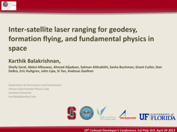
Review ofScientific InstrumentsCubeSat missions related to FIREBIRD, such as the ColoradoStudent Space Weather Experiment (CSSWE)18 and AeroCube-6(AC6),19 have proven the utility of the CubeSat platform for studying particle precipitation from the radiation belts. CSSWE was a 3U CubeSat developed by the University of Colorado Boulder, whichwas launched on September 13, 2012, and operated for just under2 years measuring electron and proton flux. CSSWE is one of themost successful CubeSat missions to date with over 19 peer reviewedpublications17 (e.g., Ref. 20). AC6 was a pair of 0.5 U CubeSats developed by The Aerospace Corporation and launched on June 19, 2014.AC6 contained multiple instruments, but of interest to the spaceweather community are three Aerospace-Teledyne microdosimetersthat measure the integral electron flux. A unique feature of AC6was the ability to control the orbital separation of the spacecraft bychanging the drag force on each, which led to the discovery of latitudinally narrow persistent spatial precipitation structures.21 FIREBIRD improves on these missions with increased time and energyresolution, which is critical to the study of microbursts.FIREBIRD was developed in collaboration between severalinstitutes. Each FIREBIRD unit is made up of a payload known asFIRE (FIREBIRD Instrument for Relativistic Electrons), which wasdeveloped at the University of New Hampshire (UNH), and a busknown as BIRD (Bus In support of Radiation Detector), which wasdeveloped at Montana State University (MSU). A key component ofFIRE is the DAPPER (Dual Amplifier Pulse Peak Energy Rundown)chip provided by The Aerospace Corporation. Preliminary GEANT(GEometry ANd Tracking)22,23 modeling and magnetic field mapping for data processing during the early mission was performed atLos Alamos National Laboratory (LANL).There are two primary FIREBIRD missions, FIREBIRD-I consisting of Flight Unit 1 and Flight Unit 2 and FIREBIRD-II consistingof Flight Unit 3 and Flight Unit 4. FIREBIRD-I was launched onDecember 6, 2013, into a 121 inclination orbit. Flight Unit 1 wasunresponsive immediately following launch, but contact was madein April and lasted into September. Flight Unit 2 was operationalimmediately following launch but only operated for 6 weeks, meaning the two units were never on simultaneously, preventing muchof the primary science. In addition, the orbital inclination kept thesatellites from reaching the latitude of the outer radiation belt onmany of their orbits. When the satellites did reach the outer belt,it was at a local time where microbursts are not typically observed.The combination of these factors resulted in FIREBIRD-I observingno verified microbursts during its lifetime.FIREBIRD-II is a follow-on mission to FIREBIRD-I with identical instrumentation and improved satellite systems. It was determined that the short lifetime of FIREBIRD-I was primarily dueto the power system. During the development of FIREBIRD-II, anupdated power system was built in house with a focus on simplicity and robustness (see Sec. IV for more detail). FIREBIRD-II waslaunched on January 31, 2015, into a 99.1 inclination orbit, andboth units were operational an hour following launch. FIREBIRD-IIhas now been in orbit for five years. Flight Unit 3 (FU3) had a battery failure in November 2019 preventing further science collectionbut continues to operate in an engineering mode. FU4 continues tooperate and return high quality data. For the remainder of this paper,“FIREBIRD” will refer to FIREBIRD-II unless otherwise noted.The primary design requirements of FIREBIRD can be directlylinked to the science questions it seeks to answer. FIREBIRDRev. Sci. Instrum. 91, 034503 (2020); doi: 10.1063/1.5137905Published under license by AIP s the scale size of microbursts by having a pair of observations in close proximity. If a microburst is observed by both flightunits simultaneously, it must be larger than the separation betweenthe two units. Both flight units began taking data an hour afterrelease from the launch vehicle, corresponding to a separation ofless than 10 km to make this measurement. The FIREBIRD energyrange was chosen to probe the energy gap between the SAMPEXHILT energies, with five energy channels ranging from 200 keVto 1 MeV and a sixth 1 MeV channel. Addressing the total electron loss globally did not drive any additional design considerationsbut underlines the importance of combining FIREBIRD observations with other sources to present a more complete picture ofmicroburst dynamics. Significant focus has been placed on magnetic conjunctions between FIREBIRD and other magnetosphericmissions.FIG. 3. An example of the energy spectrum of a microburst observed by FU3on October 11, 2018. (a) Data from the collimated detector on FU3. The verticaldashed gray line indicates the microburst being analyzed. (b) Modeled electronflux for this microburst. The solid gray line is the modeled flux function, assumedto be e-folding, found using the GEANT mass model (see Sec. V for more detail).The points are found by dividing the observed counts by an effective geometricfactor calculated from the modeled flux function. The error bars are calculated as N counts and then scaled by the effective geometric factor.91, 034503-3
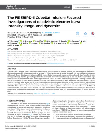
Review ofScientific InstrumentsFIREBIRD has been successful in addressing each of its science objectives. Crew et al.24 identified microbursts observed simultaneously on each FIREBIRD unit at a separation of 11 km. Thisimplies that the spatial size of those microbursts must have beenat least 11 km and represents the first direct measurement of amicroburst’s scale size. Shumko et al.25 identified a bouncing packetof microburst electrons observed by both FIREBIRD units and calculated a minimum latitudinal scale size of 30 km based on satelliteposition and a longitudinal scale size of 50 km using drift time analysis. FIREBIRD has observed thousands of microbursts at a varietyof geomagnetic conditions, allowing an in depth look at the spectralproperties of microbursts, which is currently underway. An examplemicroburst spectrum from this study is presented in Fig. 3. UsingFIREBIRD data combined with AC6 and the Balloon Array for Radiation Belt Storm Probes (RSBPs) (Van Allen Probes) RelativisticElectron Losses (BARREL),26 Anderson et al.27 was able to determine the spatial scale and duration of a particular microburst region,which helps constrain the global microburst loss estimates.FIREBIRD has also contributed to additional science beyondits primary objectives. Another objective of microburst sciencehas been to identify the mechanism that scatters microburst electrons into the loss cone. The most likely candidate is whistlermode chorus28 that have similar temporal and spatial characteristics with microbursts.7,12,29–32 Using a close conjunction betweenVan Allen Probe A33 and FU4, Breneman et al.34 demonstrateda direct link between chorus wave activity and microburst generation. FIREBIRD has also contributed to magnetospheric sciencebeyond microbursts. Capannolo et al.35 used FIREBIRD in conjunction with Van Allen Probe A and other nearby wave measurements to study the electron precipitation caused by Electromagnetic ion cyclotron (EMIC) waves. In addition, there are ongoinginvestigations using FIREBIRD data into the effect of electronprecipitation on atmospheric chemistry and the signature ofmicrobursts when viewed from the Poker Flat Incoherent Scatter Radar (PFISR).36 New FIREBIRD data are uploaded daily tohttp://solar.physics.montana.edu/FIREBIRD II/.)III. DETECTORSThe FIRE instrument package was developed at the University of New Hampshire, containing two detectors referred to as thecollimated and surface detectors. Each detector is a 1500 μm thick,32 mm diameter silicon solid-state detector, which were acquired assurplus from a previous National Oceanic and Atmospheric Administration (NOAA) mission. Each detector can fully absorb electronsup to 1050 keV above which some penetration will occur. The detectors are set inside an aluminum housing with an aluminum foilcovering the entrance to make the housing light tight and stoplow energy particles. Particles in the energy range of interest loseapproximately 25 keV going through the foil, which is negligiblecompared to the 200 keV minimum energy. The collimated detector has an additional aluminum collimator above the housing, whichreduces the angular response and geometric factor of that detector.Figure 4 shows a FIREBIRD unit during integration and testing (top)and one of the detectors in an opened collimated housing (bottom).The angular response and geometric factor are described in detail inSec. V.Rev. Sci. Instrum. 91, 034503 (2020); doi: 10.1063/1.5137905Published under license by AIP PublishingARTICLEscitation.org/journal/rsiFIG. 4. (a) One of the FIREBIRD-I units during integration and testing. The spacecraft bus is the stack of boards resting on the table, and the instrument boards areheld in the clamp. The detectors are within the covered housings protruding fromthe instrument board, with the collimated detector at the upper left (circular) andsurface detector at the bottom right (square). The instrument boards from top tobottom are the analog board, digital board, and power board. (b) A detector insidea collimated housing. The collimator is visible as the top piece of the housing. Thealuminum foil (not shown) is placed between the delrin ring and the top of thehousing.The initial pulse processing is done using a DAPPER (DualAmplifier Pulse Peak Energy Rundown) chip that was providedby The Aerospace Corporation (see Sec. 4 of Ref. 37), originallydeveloped for use in the Fly’s Eye Energetic Particle Spectrometer(FEEPS) instrument on the Magnetospheric MultiScale (MMS) mission.37 The DAPPER creates a fixed-height, variable width pulse witha duration linearly proportional to the input signal from the detector. This pulse is then timed by a Field-Programmable Gate Array(FPGA) on the digital board and mapped into a digital bin rangingfrom 0 to 255. Due to telemetry constraints, the 256 digital channelsare down-sampled to six energy channels, which make up the highresolution data product (see Sec. VI). The borders between the sixenergy channels are on-orbit configurable, allowing portions of theenergy spectrum to be investigated in fine resolution.The DAPPER has an on-board test pulser that can be usedto assess instrument health. During a pulser test, FIREBIRD stepsthrough the digital channels to sample the response across theenergy range. The signal appears as a Gaussian peak with a measurable Full Width at Half Maximum (FWHM) and peak location. Thetest pulser was utilized for instrument testing on each unit beforelaunch and has been run twice in orbit, once in November 2017 andagain in September 2018 (Fig. 5). Additional pulser tests are plannedto be run each year to monitor any changes in detector response.91, 034503-4
Review ofScientific InstrumentsARTICLEscitation.org/journal/rsiFIG. 5. Comparison of the test pulser runs performed on FIREBIRD-II. Each curve has been normalized such that its integral is unity. The FU3 collimated detector (a) showsa shift in the peak location indicating a shift in the gain. The FU3 surface detector (b) shows a large shift in gain, and much of the orbital test falls in digital bins that were notsampled. The precise status of the surface detector is unknown, but it is clear that it no longer functions as intended. The FU4 collimated detector (c) shows a similar peaklocation but broader peak width, indicating a similar gain but increased detector noise. The surface detector on FU4 has not functioned since launch.A shift in the peak location, such as observed on the FU3 collimated detector [Fig. 5(a)], indicates the gain of the digital channelshas shifted, causing each bin to contain a different energy than initially calibrated. An increase in peak width, such as observed on theFU4 collimated detector [Fig. 5(c)], indicates an increase in detectornoise. The surface detector on FU3 [Fig. 5(b)] has seen a large changein the test pulser response. Most of the orbital test data fell into digital bins that were not sampled for the test, so the precise nature ofthe detector is unknown; however, it is clear from the pulser teststhat it no longer functions as intended. A qualitative change in theFU3 surface time series data was first noticed in late July 2015, nearthe end of campaign 4 (see Sec. VII), but the detector performed asexpected for the first four campaigns. The surface detector on FU4has not functioned since launch.IV. SPACECRAFT SYSTEMSThe spacecraft structure and bus were assembled largely fromCommercial Off The Shelf (COTS) hardware by Montana State University. The structure is a modified Pumpkin, Inc., 1.5 U chassis withsolar panels mounted to each of the 10 15 cm2 faces with a smallerpanel attached to the bottom of the satellite. For FIREBIRD-I, thesolar panels were designed and assembled in-house at MSU; however, this proved to be very labor intensive, so FIREBIRD-II usedprofessionally assembled panels from Vanguard Electronics.The spacecraft bus primarily consists of four boards: Command and Data Handling (CDH), Communications (COMM),Multi-Function Interface Board (MFIB), and Electrical Power System (EPS). The CDH from Pumpkin, Inc., is a Motherboard andPluggable Processor Module that controls all subsystems on thespacecraft and stores and executes on-orbit configurable CommandSequences (CMDSEQs). The COMM transceiver is obtained fromAstronautical Development, LLC. He-100 radio with a VHF uplinkand an ultrahigh frequency (UHF) downlink and operates in theRev. Sci. Instrum. 91, 034503 (2020); doi: 10.1063/1.5137905Published under license by AIP PublishingAmateur radio bands. The radio is connected to a monopole antennafor each band made from spring steel tape measures. The MFIB wasdesigned and built at MSU and acts as an interface to the FIREpayload and any other subsystem that could not be directly connected to one of the COTS subsystems. The MFIB also features aPIC24F microcontroller, a 2 GB NAND flash for FIRE data processing and storage, and an OEMV1 GPS receiver from NovAtel, Inc.,for synchronizing the Real Time Clock (RTC) on the CDH.The CDH, COMM, and MFIB boards flew on both FIREBIRDI and FIREBIRD-II with some minor adjustments based on lessonslearned from the previous mission. The EPS on FIREBIRD-I wasdeveloped by a commercial aerospace partner considering enteringthe CubeSat market. The EPS was designed for a higher electricalload, such as those of a 3 U or 6 U CubeSat and was, therefore, veryinefficient under FIREBIRD-I’s smaller loads. Flaws in this boardled to the batteries being overcharged when the satellites had precessed into a full-sun orbit leading to battery degradation and anincreased number of resets under high load. This was the primarycause of FIREBIRD-I’s short lifetime. For FIREBIRD-II, a new EPSwas designed and built at MSU based on the first MSU satellite, theHiscock Radiation Belt Explorer,38 which remained operational forseveral years. The new EPS is based on a Direct Energy Transfer system where the batteries are directly connected to the solar arraysvia a COTS battery protection circuit. When the batteries are fullycharged and the solar panels are providing sufficient power, the batteries are disconnected from the system to prevent over-charging,and the solar panels will power the entire spacecraft. If the systempower consumption increases, such as during radio transmission, orthe power from the panels decrease, the batteries are reconnected topower the system.2Another key feature of the new EPS is a hardware WatchDogTimer (WDT), which power cycles the entire spacecraft every 12 h.By resetting every 12 h, any single event upsets due to radiationstrikes or software bugs can be resolved without intervention from91, 034503-5
Review ofScientific InstrumentsARTICLEthe ground. There have been several instances where the spacecrafthave latched up and been unresponsive to ground commands, butin each case, the spacecraft returned to normal functionality afterthe WDT was triggered. The WDT has been an important factor inthe longevity of FIREBIRD-II.The CDH flight software is implemented in the C language inthe μC/OS-II operating system from Micrium, Inc. The softwarewas designed to be highly modular and configurable and achievesthis primarily through leveraging the built-in command sequencer.Each CMDSEQ is a list of instructions for the spacecraft, which canbe executed manually via radio uplink, called by other commandsequences, or triggered by telemetry alarms generated by the telemetry monitor module. On each boot, the first CMDSEQ is executed,which then configures the spacecraft by calling other configurationCMDSEQs. Each CMDSEQ can be fully modified on-orbit if a flawis found or to adjust parameters to better meet science goals (seeSec. VII A).scitation.org/journal/rsiFigure 6(a) shows the energy dependent electron geometric factor for each of the energy bins on the FU3 collimated detector. Withthe exception of the 1 MeV channel, the geometric factor acrossthe nominal energy range of each channel is approximately 6 cm2sr, compared with an analytic geometric factor of 9 cm2 sr determined from the detector geometry.41 The FIREBIRD data productreports electron flux using the analytic geometric factors, but theV. DETECTOR RESPONSE MODELING IN GEANT4A FIREBIRD mass model has been created in GEANT4 forpurposes of modeling detector response. GEANT uses Monte Carlomethods to simulate particle interactions and propagation throughmatter.22,23 The mass model was reconstructed from the finalmechanical drawings of FIREBIRD. The detectors and elementsnear the detectors were modeled with high fidelity, while elementsfurther away from the detectors were modeled as blocks of material that approximate the material properties and geometry of thespacecraft.Electrons with a random energy according to a 1/x distribution between 200 keV and 2 MeV are launched from a randomlocation on a 25 cm radius sphere centered between the two detectors. The launch angle is selected according to a cosine distribution to create an isotropic flux within the source sphere. The initialconditions of each particle were determined using the Ranecu Random engine and General Particle Source GEANT packages.22,39 Eachlaunched electron interacts with the FIREBIRD mass model, and theamount of energy deposited in the detector is calculated. The physical processes considered in the model were determined using thephysics list recommended by the GEANT documentation for spacecraft analysis and particle energies typically found in the radiationbelts.For each electron launched in the simulation, the incidentenergy, incident angle, and energy deposited in the detector arerecorded. The incident energies are binned into 99 logarithmicallyspaced bins with roughly equal counts due to the 1/x energy distribution. The deposited energies in each incident energy bin are thenbinned by the FIREBIRD energy channel boundaries to determinethe detector response. For each incident energy bin, the geometricfactor for a FIREBIRD energy channel isG(E) n(E),4π2 r2 Ni(1)where n(E) is the number of electrons deposited in FIREBIRDenergy channel E, r is the radius of the launch sphere, and N i isthe total number of electrons launched within the incident energybin.40Rev. Sci. Instrum. 91, 034503 (2020); doi: 10.1063/1.5137905Published under license by AIP PublishingFIG. 6. A summary of GEANT modeling of the detectors aboard FU3. FU4 (notshown) has a similar geometric factor and angular response. (a) The energydependent electron geometric factor calculated with GEANT for the collimateddetector on FU3. The colored bar at the top indicates the nominal energy ranges.(b) The energy dependent proton geometric factor for the collimated detector onFU3. The differential channels are only sensitive to a narrow range of proton energies between 1 MeV and 1.1 MeV. Proton contamination will only be present duringperiods of high energy proton flux and will predominantly appear in the integralchannel. (c) Angular response of the FU3 detectors to mono-energetic 750 keVelectrons.91, 034503-6
Review ofScientific InstrumentsARTICLEscitation.org/journal/rsiTABLE I. Energy ranges of the FIREBIRD detectors (keV) and median geometric factors (cm2 sr) during campaigns 1–20. The surface detector on FU4 has not functioned sincelaunch, so its energy ranges are excluded. The response of the surface detector on FU3 changed significantly in July 2015 (see Sec. III), so the values shown here are onlycorrect up until then.FU3 CollimatedEnergy range (keV)FU3 Surface2FU4 CollimatedG factor (cm sr)Energy range (keV)G factor (cm sr)Energy range (keV)G factor (cm2 .2–480.3480.3–683.0683.0–950.1 383.6383.6–520.3520.3–720.7720.7–985.0 07.6–554.8554.8–770.7770.7–1055.2 1055.2results of this modeling indicate the true flux in the collimated detector is about 50% higher than report
1 Physics Department, Montana State University, Bozeman, Montana 59717, USA . FIREBIRD-II is a National Science Foundation funded CubeSat mission designed to study the scale size and energy spectrum of relativistic electron microbursts. The mission consists of two identical 1.5 U CubeSats in a low earth polar orbit, each with two solid state .