Transcription
Since 1912, Chance has been the international leader in earth anchoring. Ourhelical piers and anchors are used worldwide to secure soil retention projects anddeep foundation applications such as residential and commercial buildings, towerfoundations and heavy equipment foundations.Engineered for dependability and long-term stability, CHANCE helical piersand anchors feature exclusive anchoring techniques, tools, designs and sizes thatmake other foundation methods a thing of the past.Approved by all national building code agencies, CHANCE helical piers andanchors are your first line of defense against poor soil conditions, landslides,floods and time.With nearly 400 dealers and distributors worldwide, Chance is ready to provideyou everything you need to get the job done right. Chance offers engineeringguidance, field supervision, accessibility, warehouses, material traceability, AWCcertified welders, technical support and complete documentation.Ask a distributor near you for our comprehensive design manual (hardcopyor CD) or download a complete CSI Manu-Spec online. Demand a betterfoundation today. Locate your nearest distributor at www.abchance.com.Our tagline is our promise. CHANCE helical piers and anchors go down with powerinto the ground and are accurate, level and right the first time. The result is solidstability.fromISO 9001:2000A.B. CHANCE, a Division of Hubbell Power Systems, Inc.210 N. Allen, Centralia, MO 65240 USAEmail: hpsliterature@hps.hubbell.comTel: 573/682-8414 Fax: 573/682-8660Certificate No.001136Because Hubbell has a policy of continuous product improvement, we reserve the right to change design and specifications without notice. Copyright 2005 Hubbell, Inc. / Printed in USA / A&J40M9/05 / Bulletin 31-0502
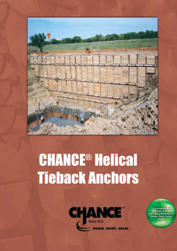
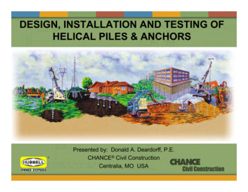
Typical construction applications: Building-site preparation Roadways Retaining wallsFeatures Levees Dams Revetments Predictable results Cost-effective method Easy to store, reusable Pre-engineered system Labor-saving, keeps crew small Screws into place (not predrilled) Site-specific to conditions and loads Terminations for various threadbars Less equipment than grouted tendons Bearing device, not friction dependent Extendable with bolted joint connectionBenefits Installs in any weather Installs in limited access areas No excavation or spoils to remove Immediate proof testing and loading Permanent or temporary (removable) Labor saving - as few as four on a crew Capacity proportional to installing torque No concrete trucks or grout pumps needed Install with equipment for grouted tendons
Typical construction applications: Building-site preparation Roadways Retaining wallsFeatures Levees Dams Revetments Predictable results Cost-effective method Easy to store, reusable Pre-engineered system Labor-saving, keeps crew small Screws into place (not predrilled) Site-specific to conditions and loads Terminations for various threadbars Less equipment than grouted tendons Bearing device, not friction dependent Extendable with bolted joint connectionBenefits Installs in any weather Installs in limited access areas No excavation or spoils to remove Immediate proof testing and loading Permanent or temporary (removable) Labor saving - as few as four on a crew Capacity proportional to installing torque No concrete trucks or grout pumps needed Install with equipment for grouted tendons
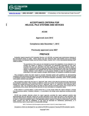
Immediate pull testing of helical tieback anchors afterinstallation serves as a check on design procedures andeliminates deflection at working loads.No delays because there is no grout Typical production rate of 30 to 40 per day for installing and testing No holes to drill Cuts labor and equipment costs Can save 30 per cent while obtaining high anchor-load capacitiesSolves construction problems In cohesive soils, no belled and/or long sockets In non-cohesive soils, no casings or grouted sockets Bearing mode (not friction mode) anchors No de-watering for below-water-table applicationsDesign and buildmeans just that with HeliCAP Software!HeliCAP Engineering Software helps designprofessionals quickly derive the proper helical tieback anchor for site- and load-specificdata. For a free demo, visit www.abchance.com. Then contact your local Distributor orTerritory Manager about how to get a copyfor your PC.Site-specific basics of screw anchor designTwo typical steps to anchorage design:1. Select helix configuration based on accurate soil characteristics data and tension load.2. Select shaft configuration based on tension load and anticipated installation torque. Anchor load capacity equals the sum of all its individual helix bearing capacities. Bearingcapacity of each helix equals the product of its projected area and bearing pressure. Pre-engineered CHANCE screw anchors optimize helix spacing at three times the nextlower helix diameter. This assures more predictable torque-to-capacity relationship. Holding capacity is proportional to installation torque (recommended 10 lb per ft-lb). Monitor torque while installing to ensure a minimum and not to exceed anchor rating. CSI guide specs and our model specifications are available on www.abchance.com
Immediate pull testing of helical tieback anchors afterinstallation serves as a check on design procedures andeliminates deflection at working loads.No delays because there is no grout Typical production rate of 30 to 40 per day for installing and testing No holes to drill Cuts labor and equipment costs Can save 30 per cent while obtaining high anchor-load capacitiesSolves construction problems In cohesive soils, no belled and/or long sockets In non-cohesive soils, no casings or grouted sockets Bearing mode (not friction mode) anchors No de-watering for below-water-table applicationsDesign and buildmeans just that with HeliCAP Software!HeliCAP Engineering Software helps designprofessionals quickly derive the proper helical tieback anchor for site- and load-specificdata. For a free demo, visit www.abchance.com. Then contact your local Distributor orTerritory Manager about how to get a copyfor your PC.Site-specific basics of screw anchor designTwo typical steps to anchorage design:1. Select helix configuration based on accurate soil characteristics data and tension load.2. Select shaft configuration based on tension load and anticipated installation torque. Anchor load capacity equals the sum of all its individual helix bearing capacities. Bearingcapacity of each helix equals the product of its projected area and bearing pressure. Pre-engineered CHANCE screw anchors optimize helix spacing at three times the nextlower helix diameter. This assures more predictable torque-to-capacity relationship. Holding capacity is proportional to installation torque (recommended 10 lb per ft-lb). Monitor torque while installing to ensure a minimum and not to exceed anchor rating. CSI guide specs and our model specifications are available on www.abchance.com
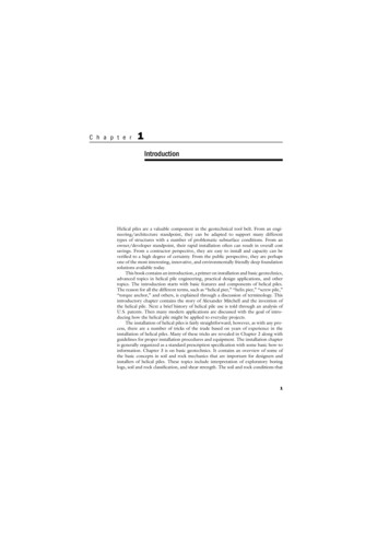
Helical Tieback Anchors have shafts in four square sizes (1-1/2”, 1-3/4”,2” and 2-1/4”) with helices in configurations of two to four and diameters from 6” to 14”. All components are available hot-dip galvanizedper ASTM A 153 after fabrication.Terminations fit threadbar or provide a threaded stud to work with prefabricated or site-made lockoff devices. Other termination fittings also are available. In some cases, the through-hole at the shaftend may be simply crosspinned. 1” Threadbar Adapter for 1-1/2”, 1-3/4”and 2” Tieback Anchor Types 1-1/4” Threadbar Adapter for 2” and 2-1/4”Tieback Anchor Types 1-3/8” Threadbar Adapter for 2-1/4” TiebackAnchor TypesExtensionsPlain and helical extensions are used to reach competent load-bearing soil. Plainextensions range from 37” to 124” long. Helical extensions range from 48” to124” long with 14”-diameter helices in single, double and triple configurations.Forged integral coupling sockets bolt-up quickly and efficently transfer installing torque. Threaded Stud Socket Adapter for 1-1/2” Tieback Anchors Threaded Stud Clevis Adapter for 1-3/4” Tieback AnchorsHelical TiebackAnchor TypeLead SectionsFor job-specific combinations, leading sections range from 30” to 124” long intwo-, three- or four-helix configurations usually with increasing diameters fromthe 6”, 8”, 10”, 12” and 14” range.Sizeinches(mm)Torque Ratingft-lb(N-m)Ultimate Capacity*kip(kN)SS5Square Shaft1.50(38.1)5,500(7,500)55(245)SS150Square Shaft1.50(38.1)7,000(9,500)70(312)SS175Square Shaft1.75(44.5)10,000(13,600)100(445)SS200Square Shaft2.00(50.8)15,000(20,300)150(668)SS225Square Shaft2.25(57.2)20,000(27,100)200(890)* The Ultimate Capacity is based on the Installation Torque-Capacity relationship in soil.For more detailed design information, contact your local Civil Construction distributor found at www.abchance.com.Calculate bearing capacities using our exclusive HeliCAP Engineering Software.Demo available at www.abchance.com.
Helical Tieback Anchors have shafts in four square sizes (1-1/2”, 1-3/4”,2” and 2-1/4”) with helices in configurations of two to four and diameters from 6” to 14”. All components are available hot-dip galvanizedper ASTM A 153 after fabrication.Terminations fit threadbar or provide a threaded stud to work with prefabricated or site-made lockoff devices. Other termination fittings also are available. In some cases, the through-hole at the shaftend may be simply crosspinned. 1” Threadbar Adapter for 1-1/2”, 1-3/4”and 2” Tieback Anchor Types 1-1/4” Threadbar Adapter for 2” and 2-1/4”Tieback Anchor Types 1-3/8” Threadbar Adapter for 2-1/4” TiebackAnchor TypesExtensionsPlain and helical extensions are used to reach competent load-bearing soil. Plainextensions range from 37” to 124” long. Helical extensions range from 48” to124” long with 14”-diameter helices in single, double and triple configurations.Forged integral coupling sockets bolt-up quickly and efficently transfer installing torque. Threaded Stud Socket Adapter for 1-1/2” Tieback Anchors Threaded Stud Clevis Adapter for 1-3/4” Tieback AnchorsHelical TiebackAnchor TypeLead SectionsFor job-specific combinations, leading sections range from 30” to 124” long intwo-, three- or four-helix configurations usually with increasing diameters fromthe 6”, 8”, 10”, 12” and 14” range.Sizeinches(mm)Torque Ratingft-lb(N-m)Ultimate Capacity*kip(kN)SS5Square Shaft1.50(38.1)5,500(7,500)55(245)SS150Square Shaft1.50(38.1)7,000(9,500)70(312)SS175Square Shaft1.75(44.5)10,000(13,600)100(445)SS200Square Shaft2.00(50.8)15,000(20,300)150(668)SS225Square Shaft2.25(57.2)20,000(27,100)200(890)* The Ultimate Capacity is based on the Installation Torque-Capacity relationship in soil.For more detailed design information, contact your local Civil Construction distributor found at www.abchance.com.Calculate bearing capacities using our exclusive HeliCAP Engineering Software.Demo available at www.abchance.com.
Since 1912, Chance has been the international leader in earth anchoring. Ourhelical piers and anchors are used worldwide to secure soil retention projects anddeep foundation applications such as residential and commercial buildings, towerfoundations and heavy equipment foundations.Engineered for dependability and long-term stability, CHANCE helical piersand anchors feature exclusive anchoring techniques, tools, designs and sizes thatmake other foundation methods a thing of the past.Approved by all national building code agencies, CHANCE helical piers andanchors are your first line of defense against poor soil conditions, landslides,floods and time.With nearly 400 dealers and distributors worldwide, Chance is ready to provideyou everything you need to get the job done right. Chance offers engineeringguidance, field supervision, accessibility, warehouses, material traceability, AWCcertified welders, technical support and complete documentation.Ask a distributor near you for our comprehensive design manual (hardcopyor CD) or download a complete CSI Manu-Spec online. Demand a betterfoundation today. Locate your nearest distributor at www.abchance.com.Our tagline is our promise. CHANCE helical piers and anchors go down with powerinto the ground and are accurate, level and right the first time. The result is solidstability.fromISO 9001:2000A.B. CHANCE, a Division of Hubbell Power Systems, Inc.210 N. Allen, Centralia, MO 65240 USAEmail: hpsliterature@hps.hubbell.comTel: 573/682-8414 Fax: 573/682-8660Certificate No.001136Because Hubbell has a policy of continuous product improvement, we reserve the right to change design and specifications without notice. Copyright 2005 Hubbell, Inc. / Printed in USA / A&J40M9/05 / Bulletin 31-0502
For more detailed design information, contact your local Civil Construction distributor found at www.abchance.com. Extensions Plain and helical extensions are used to reach competent load-bearing soil. Plain extensions range from 37" to 124" long. Helical extensions range from 48" to