Transcription
GUIDE TO MODEL SPECIFICATION –CHANCE Civil ConstructionHELICAL TIEBACK ANCHORS FOR EARTHRETENTIONTYPES OF SPECIFICATIONSThe three types of specifications that are used for HELICAL TIEBACK ANCHOR projects are:Open Specifications: The Contractor is given the responsibility for the scope and design of the helicaltieback anchor installation. In addition, the construction, capacity, and performance of the helical tiebackanchor are the sole responsibility of the Contractor. This specification assumes that the Owner or Designerhas provided the required structural loads. This specification type is most common for securing bids ontemporary projects, and is not recommended for permanent applications.Performance Specifications: The Contractor is given the responsibility for certain design and/orconstruction procedures, but must demonstrate to the Owner through testing and/or mutually agreed uponacceptance criteria that the production helical tiebacks meet or exceed the specified performance parameters.This specification assumes that the location and the required loads of the helical tieback anchor have beenspecified. The Contractor and Owner share the responsibility for the work.Prescriptive Specifications: The Owner has the sole responsibility for the scope and design of the helicaltieback anchor installation and specifies the procedures that must be followed. Prescriptive specificationsmandate the Owner to be responsible for the proper performance of the production helical tieback anchors.The Contractor is responsible for fulfilling the obligations/details as specified in the construction documents.Performance specifications are the most common and allow Contractors to use their unique installationmethods and experience for any given site conditions. Owners receive the benefit of value engineering,which can result in lower costs.The Owner, Designer, and Contractor will be jointly responsible for the design, installation, acceptance, andperformance of the helical tieback anchor. The installation of a helical tieback requires specializedGuide to Model Specification –HELICAL TIEBACK ANCHORS – Earth RetentionA.B. Chance A Division of Hubbell Power Systems1 Copyright 2006 Hubbell, Inc.
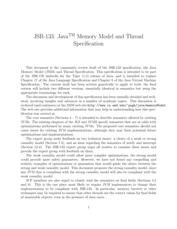
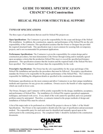
equipment, techniques, and trained work crews. Every detail of the work cannot be specified, and everypotential problem cannot be anticipated. Therefore, a contractor trained in the proper methods of design andinstallation of screw anchor tiebacks must be selected.A list of the major tasks to be performed on a helical tieback anchor project is shown in Table-1 of the ModelSpecifications. The Owner or his representative should select the type of specification and procurementmethod. The responsible party for each task must be identified and mutually agreed upon at the earliest pointin the contracting process. The completed Table-1 should be included in the construction documents.The process of continuous communication between all the parties involved is essential to achieve asatisfactory result. Clear communication and close cooperation are particularly important in the start-upphase and in testing. In addition, a timely preparation and review of all submittals is critical.This model specification can be adapted to each of the three types of specifications. However, it is primarilywritten for the performance type. The identity of the “Contractor” and the “Owner” is always well defined,unlike that of the “Designer” or “Engineer”. For example, the “Engineer” may be an employee(s) of theContractor, or a third party consultant hired to secure a lower cost alternative during the bidding process. Incontrast, the “Engineer” may be the Owner, an employee(s) of the Owner, or a representative hired by theOwner. It is recommended that the Engineer be a third party agency employed by the Owner to serve in theowner's best interests during the various stages of the contract.For purposes of this Model Specification, the subject is a high capacity HELICAL TIEBACK ANCHORmanufactured by CHANCE Civil Construction. The helical tieback anchor consists of one or more helicalbearing plates attached at the tip of a high strength central steel shaft. The central steel shaft consists of solidsquare shaft of various sections. Said shaft is connected to the wall face via thread-bar, bearing plate, andload nut.It is suggested that the specification writer accurately andcompletely modify this model to suit his/her particular case.Items in italics as such may be considered as “Commentary” and as such may be deleted or retained to suitthe needs of the specification writer.Guide to Model Specification –HELICAL TIEBACK ANCHORS – Earth RetentionA.B. Chance A Division of Hubbell Power Systems2 Copyright 2006 Hubbell, Inc.
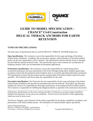
The following is list of general references that will provide additional background to HELICAL TIEBACKANCHOR technology:A. B. Chance Company, HELICAL PIER Foundation Systems, Technical Manual, Bulletin 01-9601,Copyright 2000 Hubbell, 210 North Allen St., Centralia, MO 65240Atlas Systems, Inc., Technical Manual, 2005, Copyright 2004 – Atlas Systems, Inc, 1026-B South PowellRoad, Independence, MO 64056Bobbitt, D.E., and Thorsten, Richard, The Use of Helical Tieback Anchors for a Permanent Retaining Wall,Bulletin 31-8902, Presented at the 1989 Foundation Congress – Northwestern University – Evanston, IllinoisSeider, Gary L., and Smith, Walter P., Helical Tieback Anchors Help Reconstruct Failed Sheet Pile Wall,Bulletin 31-9502, Presented at the 1995 46th Highway Geology Symposium – Charleston, West VirginiaHoyt, R.M. and Clemence, S.P., 1989. Uplift Capacity of Helical Anchors in Soil. Proceedings of the 12thInternational Conference on Soil Mechanics and Foundation Engineering, Vol. 2, pp. 1019-1022.Clemence, S.P., Thorsten, Richard E., and Edwards, Bill, Helical Anchors: Overview of Application andDesign, Bulletin 31-9001, reprinted from ADSC Foundation Drilling Magazine, Copyright 1990 A. B.Chance Company, 210 North Allen St., Centralia, MO 65240Figure-1 Typical Cross SectionGuide to Model Specification –HELICAL TIEBACK ANCHORS – Earth RetentionA.B. Chance A Division of Hubbell Power Systems3 Copyright 2006 Hubbell, Inc.
CHANCE Civil ConstructionHELICAL TIEBACK ANCHORSMODEL SPECIFICATION1. GENERAL1.1 Purpose of SpecificationThe purpose of this specification is to detail the furnishing of all designs, materials, tools, equipment, laborand supervision, and installation techniques necessary to install HELICAL TIEBACK ANCHORS asdetailed on the drawings, including connection details. This shall include provisions for load testing thatmay be part of the scope of workSpecifier Note: This specification may require modification to account for unusual and/or unforeseen siteand subsurface conditions and the particular circumstances of the project.1.2 Scope of WorkThis work consists of furnishing all necessary engineering and design services (if required), supervision,labor, tools, materials, and equipment to perform all work necessary to install the HELICAL TIEBACKANCHORS, at (location, City, State/Province) for (Company, State or Private Authority) per thespecifications described herein, and as shown on the drawings. The Contractor shall install a helical anchorthat will develop the load capacities as detailed on the drawings. This may also include provisions for loadtesting to verify tieback capacity and deflection, if part of the scope of work. The responsibilities and dutiesof the respective parties for this project are summarized in Table-1.Guide to Model Specification –HELICAL TIEBACK ANCHORS – Earth RetentionA.B. Chance A Division of Hubbell Power Systems4 Copyright 2006 Hubbell, Inc.
Table-1. Tasks and Responsibilities to be Allocated for Helical Tieback Anchor Y*Site Investigation, Geotechnical Investigation, Site Survey, and potentialwork restrictionsType of specification, requirement for a pre-contract testing program, andprocurement methodObtaining easementsOverall scope of work, design of the anchored structure – includingdesign loads (vertical, horizontal, etc.), anchor locations, and anchorspacing and orientationDefinition and qualification of safety factorsCalculation/estimation of allowable structural and/or anchor movement inservice (acceptance criteria)Definition of service life (temporary – months or permanent - years) andrequired degree of corrosion protection based on site conditionsType and number of tests (pre-contract, pre-production and production)Minimum total anchor length, depth to bearing stratumHelical Tieback Anchor components and detailsDetails of corrosion protection, if requiredDetails of anchor connection to structure (e.g., for static and seismicconditions)Preparation of Drawings and test reportsEvaluation of test resultsConstruction methods, schedule, sequencing, and coordination of workRequirements of field production control, including logging of installationtorque vs. installed depthSupervision of workLong-term monitoring* To be filled in by specification writer.1.3 Qualifications of the Helical Tieback Anchor ContractorThe helical anchor Contractor shall be experienced in performing design and construction of helical tiebackanchors and shall furnish all materials, labor, and supervision to perform the work. The Contractor shall betrained by CHANCE Civil Construction in the proper methods of design and installation of screw anchortiebacks. The Contractor shall provide names of on-site personnel materially involved with the work. At aminimum, these personnel shall include foreman, machine operator, and project engineer/manager.The helical tieback anchor Contractor shall not sublet the whole or any part of the contract without theexpress written permission of the Owner.Guide to Model Specification –HELICAL TIEBACK ANCHORS – Earth RetentionA.B. Chance A Division of Hubbell Power Systems5 Copyright 2006 Hubbell, Inc.
1.4 Related Project SpecificationsTo be determined by the specification writer.1.5 DefinitionsA partial list follows. The Owner may wish to add other specific, project-related items.Bearing Stratum: Soil layer(s) of sufficient strength capable of resisting the applied axial load transferredby the helical tieback.Contractor: The person/firm responsible for performing the helical tieback anchor work.Coupling: Central steel shaft connection means formed as integral part of the plain extension shaft material.For Type SS anchors, couplings are external cast sleeves, or hot upset forged sockets.Coupling Bolt(s): High strength, structural steel fasteners used to connect helical anchor segments together.For Type SS segments, the coupling bolt transfers axial load only.Design Load (DL): Maximum anticipated service load applied to the helical anchor. A.k.a. Working Load(WL).Free Length: Length of plain extension acting as a tendon, which is free to elongate elastically. A.k.a. unbonded length or stressing length. Helix plates shall not be located in free length section of tieback.Minimum free length shall be specified on a project specific basis.Helical Extension: Helical tieback anchor component installed immediately following the lead or startersection, if required. This component consists of one or more helix plates welded to a central steel shaft offinite length. Function is to increase bearing area.Helical Tieback Anchor: Bearing type anchor used to transfer tensile loads to soil. Helical tieback anchorsconsist of a central steel shaft, helix bearing plates, coatings, corrosion protection, and a wall connection.Helix Plate: Generally round steel plate formed into a ramped spiral. The helical shape provides the meansto install the helical tieback anchor, plus the plate transfers load to soil in end-bearing. Helix plates areavailable in various diameters and thicknesses.Lead Section: The first helical tieback anchor component installed into the soil, consisting of single ormultiple helix plates welded to a central steel shaft. A.k.a Starter Section.Performance Test: Similar to a Proof Test except a cyclic loading method is used to analyze total, elastic,and net movement of the helical anchor. Often used for pre-contract or pre-production load tests, in additionto a specified percentage of production anchors.Guide to Model Specification –HELICAL TIEBACK ANCHORS – Earth RetentionA.B. Chance A Division of Hubbell Power Systems6 Copyright 2006 Hubbell, Inc.
Plain Extension: Central steel shaft of finite length without helix plates. It is installed following theinstallation of the lead or starter section or helical extension (if used). The units are connected withcouplings and bolts. Plain extensions are used to extend the helix plates beyond the specified minimum freelength and into competent load bearing stratum.Proof Test: Incremental loading of a helical anchor, holding for a period of time, and recording the totalmovement at each load increment.Safety Factor: The ratio of the ultimate capacity to the working or design load used for the design of anystructural element.Square Shaft (SS): Solid steel, round-cornered-Square central Shaft elements ranging in size from 1-1/4” to2-1/4”. A.k.a. Type SQ.Thread Bar Adapter: Section of central steel shaft used to connect the helical anchor to the wall face via ahigh tensile strength pre-stressing thread bar.Torque Strength Rating: The maximum torque energy that can be applied to the helical tieback anchorduring installation in soil, a.k.a. allowable, or safe torque.1.6 Allowable TolerancesThe tolerances quoted in this section are suggested maximums. The actual values established for a particularproject will depend on the structural application.1.6.1Centerline of helical tieback anchor shall not be more than 6 inches from indicated plan location.1.6.2The angular tolerance between installed tieback anchor angle and design angle shall be 3 as shownon the drawings.1.7 Quality Assurance1.7.1Contractors authorized by CHANCE Civil Construction shall install helical tieback anchors. TheseContractors shall have satisfied the requirements relative to the technical aspects of the product andinstallation procedures as therein specified.1.7.2The Contractor shall employ an adequate number of skilled workers who are experienced in thenecessary crafts and who are familiar with the specified requirements and methods needed for properperformance of the work of this specification.1.7.3All helical tieback anchors shall be installed in the presence of a designated representative of theOwner unless said representative informs the Contractor otherwise. The designated representativeshall have the right of access to any and all field installation records and test reports.Guide to Model Specification –HELICAL TIEBACK ANCHORS – Earth RetentionA.B. Chance A Division of Hubbell Power Systems7 Copyright 2006 Hubbell, Inc.
1.7.4Screw anchor components as specified therein shall be manufactured by a facility whose qualitysystems comply with ISO (International Organization of Standards) 9001 requirements. Certificatesof Registration denoting ISO Standards Number shall be presented upon request to the Owner or theirrepresentative.1.7.5CHANCE Civil Construction provides a standard one-year warranty on materials and workmanshipof the product. Any additional warranty provided by the Contractor shall be issued as an addendumto this specification.1.7.6Design of helical tieback anchors shall be performed by an entity as required in accordance withexisting local code requirements or established local practices. This design work may be performedby a licensed professional engineer, an authorized CHANCE Civil Construction Contractor, ordesigner depending upon local requirements or practices.1.8 Design Criteria1.8.1Helical tieback anchors shall be designed to meet the specified loads and acceptance criteria as shownon the drawings. The calculations and drawings required from the Contractor or Engineer shall besubmitted to the Owner for review and acceptance in accordance to Section 3.1 “ConstructionSubmittals”.1.8.1.1 The allowable working load on the helical tieback anchor shall not exceed the following values:Pallowt Sut / FSWhere:PallowtSutFS allowable working load in tension (kip) Min. ultimate tensile strength of central steel shaft segment (at coupling joint) (kip) factor of safety suitable for application, i.e. temporary or permanent structuresFor permanent applications, it is recommended to use a factor of safety of two (2). For temporaryapplications, factor of safety typically ranges between 1.25 and 1.5.It is recommended to use the minimum ultimate tensile strengths as published by CHANCE CivilConstruction (shown in Table-A of the Appendix). The ultimate tensile strength may be reduced bythe ultimate capacity per helix plate(s) – depending on the number of helix plates specified and typeof shaft product used. The ultimate tensile strength may also be reduced by the torque limitedultimate capacity – depending on the type of shaft product used.1.8.1.2 The ultimate structural capacity shall be determined as:Pultt SutWhere: Pultt Ultimate structural capacity in tension (kip)Guide to Model Specification –HELICAL TIEBACK ANCHORS – Earth RetentionA.B. Chance A Division of Hubbell Power Systems8 Copyright 2006 Hubbell, Inc.
Sut Minimum ultimate tensile strength of central steel shaft (kip)It is recommended to use the minimum ultimate tensile strengths as published by CHANCE CivilConstruction (shown in Table-A of the Appendix). The ultimate tensile strength may be reduced bythe ultimate capacity per helix plate(s) – depending on the number of helix plates specified and typeof shaft family used. The ultimate tensile strength may also be reduced by the torque limited ultimatecapacity – depending on the type of shaft family used.The minimum yield strength of the central steel shaft is as follows: Type SS5: 70 ksi; Type SS125,SS1375, SS150, SS175, SS200, SS225: 90 ksi.1.8.2Individual helical tieback anchors shall be designed so that the maximum test load will not exceed 90percent of the minimum ultimate tension capacity of the central steel shaft material. The Contractorshall select the type of thread bar to be used. The thread bar shall be sized so the design load does notexceed 60 percent of the guaranteed ultimate tensile strength of the thread bar. In addition, the threadbar shall be sized so the maximum test load does not exceed 80 percent of the guaranteed ultimatetensile strength of the thread bar.1.8.3Helical tieback anchor capacity in soil shall not be relied upon from the following soil layers asdefined in the geotechnical reports:The overall length and installed torque of a helical tieback anchor shall be specified such that therequired in-soil capacity is developed by end-bearing on the helix plate(s) in an appropriate strata(s).It is recommended that the theoretical end-bearing capacity of the helix plates be determined usingHeliCAP Engineering Software or equal commercially available software. The required soilparameters (c, , , or N-values) for use with HeliCAP or equal shall be provided in the geotechnicalreports. The Owner shall determine the allowable response to axial loads.Helical anchors are not suited for solid, competent rock, but the helix plates can penetrate into densebearing soils. Appropriate and repeatable installation techniques and helical anchor terminationcriteria must be identified and verified in the field.Guide to Model Specification –HELICAL TIEBACK ANCHORS – Earth RetentionA.B. Chance A Division of Hubbell Power Systems9 Copyright 2006 Hubbell, Inc.
1.8.4Corrosion ProtectionThis section is optional (see below). Provisions of this section and Section 4.7 below may not berequired in the Specification. If this section is not used, then Section 4.7 should likewise bedeleted. The degree and extent of corrosion protection must be specified by the Owner (Table-1).Corrosion protection is a function of structure type, service life, and the overall aggressiveness of theproject soils. The need for corrosion protection of helical tieback anchors must be carefullydetermined and specified as necessary.Corrosion resistant coatings (i.e. epoxy, plastic sheath) on the lead/starter section are impracticaldue to abrasive action wearing off the coating as the soil flows over the helix plates and around thecentral steel shaft. Hot dip galvanization is the only practical means to provide a corrosion resistantcoating capable of withstanding the rigors of installation. Extension sections are typically hot-dipgalvanized, but other coatings can be specified.The following requirements are typical. The specifier should review and edit as appropriate for theproject.Structure Type: (e.g. temporary, permanent) with a temporarystructure being defined within a specified time frame (i.e. months rather than years). In general,permanent structures have a service life greater than 24 months.Temporary structures do not require corrosion protection.Service Life: (years) a typical service life of 50 years should beused unless otherwise specified. If the service life of a temporary helical tieback anchor is likely tobe extended due to construction delays, it should be considered permanent.For a service life of less than 20 years in non-aggressive soil, corrosion protection is notrecommended.Corrosion protection requirements for the various helical tieback anchor elements shall be providedmeeting the requirements of Table-B in the Appendix for:Soil: Aggressive or Non-Aggressive with optionallocation and elevation limits defined by the Specifier.For guidance on aggressiveness classification, see Table-B in the Appendix. It is recommended toretain the services of a corrosion design professional for very aggressive soils.Guide to Model Specification –HELICAL TIEBACK ANCHORS – Earth RetentionA.B. Chance A Division of Hubbell Power Systems10 Copyright 2006 Hubbell, Inc.
TABLE-2SOILCENTRALSTEEL SHAFT(Lead Section)CENTRALSTEEL N PROTECTIONAGGRESSIVEGalvanization1.ORMinimum 1/8” corrosion loss on2.outsideGalvanization1.OREpoxy coating2.ORMinimum 1/8” corrosion loss on3.outside1. Trumpet – corrosion inhibitor orgrout filledAND2. Cover, if exposedNON-AGGRESSIVEBare steelORGalvanizationBare steelORGalvanizationOREpoxy coating1. Bare SteelOR2. Trumpet – corrosion inhibitor orgrout filledNOTES:Numbered items are options.For guidance on aggressiveness classification, see Table-B of the Appendix.1. Trumpet typically extends 3’-0 to 5’-0 beyond the anchorage.The most critical area to protect from corrosion is in the vicinity of the anchorage and the portion of thethread bar immediately behind the wall. The vulnerability of this area is demonstrated by the fact that mostground anchor failures occur within a short distance of the anchorage device. Care is required in order toensure that the thread bar and central steel shaft is protected in this area. Grout-filled trumpets require ashort term seal until the grout sets and are typically filled with grout after the helical anchor has beenstressed. Grease-filled trumpets require a long-term watertight seal that can be difficult to maintain.1.9.Ground ConditionsThe Geotechnical Report, including logs of soil borings as shown on the boring location plan, shall beconsidered to be representative of the in-situ subsurface conditions likely to be encountered on the projectsite. Said Geotechnical Report shall be the used as the basis for helical tieback anchor design using generallyaccepted engineering judgement and methods.If soil borings are not available, it is suggested to install a helical anchor at various locations on the projectsite. Using the well-known installed torque vs. capacity attribute of helical anchors, a presumptive soilprofile can be generated.Guide to Model Specification –HELICAL TIEBACK ANCHORS – Earth RetentionA.B. Chance A Division of Hubbell Power Systems11 Copyright 2006 Hubbell, Inc.
The Geotechnical Report shall be provided for purposes of bidding. If during helical tieback anchorinstallation, subsurface conditions of a type and location are encountered of a frequency that were notreported, inferred and/or expected at the time of preparation of the bid, the additional costs required toovercome such conditions shall be considered as extras to be paid for.All available information related to subsurface and general site conditions should be made available to allbidders at the time of bid preparation. It is not reasonable to expect bidders to conduct supplemental siteinvestigations at their own risk and cost prior to bidding, unless the specific contract requirements call for it(Table-1) and provide for appropriate compensation. A mandatory site visit and pre-bid meeting should beheld so that the details of the project and the specifications can be thoroughly discussed. These steps willhelp avoid technical and contractual problems developing during the execution of the work, and will help allparties manage their respective risk.2REFERENCED CODES AND STANDARDSStandards listed by reference, including revisions by issuing authority, form a part of this specificationsection to the extent indicated. Standards listed are identified by issuing authority, authority abbreviation,designation number, title, or other designation established by issuing authority. Standards subsequentlyreferenced herein are referred to by issuing authority abbreviation and standard designation. In case ofconflict, the particular requirements of this specification shall prevail. The latest publication as of the issueof this specification shall govern, unless indicated otherwise.2.1 American Society for Testing and Materials (ASTM):2.1.1 ASTM A29/A29M Steel Bars, Carbon and Alloy, Hot-Wrought and Cold Finished.2.1.2 ASTM A36/A36M Structural Steel.2.1.3 ASTM A53 Pipe, Steel, Black and Hot-Dipped, Zinc-Coated Welded and Seamless.2.1.4 ASTM A153 Zinc Coating (Hot Dip) on Iron and Steel Hardware.2.1.5 ASTM A252 Welded and Seamless Steel Pipe Piles.2.1.6 ASTM A775 Electrostatic Epoxy Coating2.1.7 ASTM A193/A193M Alloy-Steel and Stainless Steel Bolting Materials for High TemperatureService.2.1.8 ASTM A320/A320M Alloy-Steel Bolting Materials for Low Temperature Service.2.1.9 ASTM A325 Standard Specification for Structural Bolts, Steel, Heat Treated, 120/105 ksi MinimumTensile Strength.2.1.10 ASTM A500 Cold-Formed Welded and Seamless Carbon Steel Structural Tubing in Rounds andShapes.2.1.11 ASTM A536 Standard Specifications for Ductile Iron Castings2.1.12 ASTM A572 HSLA Columbium-Vanadium Steels of Structural Quality.2.1.13 ASTM A615 Standard Specification for Deformed and Plain Steel Bars for Concrete Reinforcement2.1.14 ASTM A656 Hot-Rolled Structural Steel, High-Strength Low-Alloy Plate with ImprovedFormability.2.1.15 ASTM A958 Standard Specification for Steel Castings, Carbon, and Alloy, with TensileRequirements, Chemical Requirements Similar to Wrought Grades.Guide to Model Specification –HELICAL TIEBACK ANCHORS – Earth RetentionA.B. Chance A Division of Hubbell Power Systems12 Copyright 2006 Hubbell, Inc.
2.1.16 ASTM A1018 Steel, Sheet and Strip, Heavy Thickness Coils, Hot Rolled, Carbon, Structural, HighStrength Low-Alloy, Columbium or Vanadium, and High-Strength Low-Alloy with ImprovedFormability.2.1.17 ASTM D1784 Specification for Rigid Poly Vinyl Chloride (PVC) Compounds and Chlorinated PolyVinyl Chloride (CPVC) Compounds.2.1.18 ASTM D1785 Specification for Poly(Vinyl Chloride) (PVC) Plastic Pipe, Schedules 40, 80, and 120.2.1.19 ASTM D3034 Specification for Type PSM Poly(Vinyl Chloride) (PVC) Sewer Pipe and Fittings.2.1.20 ASTM D3689 Method of Testing Individual Piles Under Static Axial Tensile Load.2.2 American Welding Society (AWS):2.2.1 AWS D1.1 Structural Welding Code – Steel.2.2.2 AWS D1.2 Structural Welding Code – Reinforcing Steel.2.3 American Society of Civil Engineers (ASCE):2.3.1 ASCE 20-96 Standard Guidelines for the Design and Installation of Pile Foundations.2.4 Association of Drilled Shaft Contractors (ADSC) The International Association of FoundationDrilling:2.4.1 GEC No. 4 - Ground Anchors and Anchored Systems2.4.2 ADSC Mechanical Anchor Product Data2.5 Post Tensioning Institute (PTI):2.5.1 Recommendations for Prestressed Rock and Soil Anchors, Third Edition, Copyright 1996 By thePost-Tensioning Institute.2.6 Society of Automotive Engineers (SAE):2.6.1 SAE J429 Mechanical and Material Requirements for Externally Threaded Fasteners.3SUBMITTALS3.1 Construction Submittals3.1.1 The Contractor or Engineer shall prepare and submit to the Owner, for review and approval, workingdrawings and design calculations for the helical tieback anchor intended for use at least 14 calendardays prior to planned start of construction (but note also Paragraph 3.1.8). All submittals shall besigned and sealed by a Registered Professional Engineer currently licensed in the State/Province of.3.1.2The Contractor shall submit a detailed description of the construction procedures proposed for use tothe Owner for review. This shall include a list of major equipment to be used.3.1.3The Working Drawings shall include the following:3.1.3.a3.1.3.bHelical anchor number, location and pattern by assigned identification numberHelical anchor design loadGuide to Model Specification –HELICAL TIEBACK ANCHORS – Earth RetentionA.B. Chance A Division of Hubbell Power Systems13 Copyright 2006 Hubbell, Inc.
3.1.3.cType and size of central steel shaftType SS125 1-1/4” RCS, Type SS1375 1-3/8” RCS, Type SS5/SS150 – 1-1/2” RCS, Type SS175 – 1-3/4”RCS, Type SS200 – 2” RCS, Type SS225 – 2-1/4” RCS.3.1.3.d3.1.3.e3.1.3.f3.1.3.g3.1.3.hHelix configuration (number and diameter of helix plates)Minimum effective installation torqueMinimum overall lengthInclination of helical anchorTy
The helical anchor Contractor shall be experienced in performing design and construction of helical tieback anchors and shall furnish all materials, labor, and supervision to perform the work. The Contractor shall be trained by CHANCE Civil Construction in the proper methods of design and installation of screw anchor tiebacks.