Transcription
Aprilaire Dehumidifier Troubleshooting ManualModels 1830 & 1850Table of ContentsTroubleshooting Diagnostic Codes . 2E1, E2. 2E3, E4. 3E5, E6 & E7 . 7E8 . 8E9 9Verifying Capacity. 10Water Leaks . 15Fan Does Not Function . 15Circuit Breaker Trips . 16Parts List . 17Electrical Schematic. 18Instruments you will need to complete troubleshooting:1. Digital Multi-Meter (DMM) capability of measuring AC and DC voltage Resistance CapacitanceMinimum tools needed to complete troubleshooting:1.2.3.4.!Torx T20 and T25 screwdrivers or driver bitsSmall (terminal) flat head screwdriverNeedle nose pliersLevel (to troubleshoot water leak claims)WARNING: 120-volts can cause serious injury or death. Do not touch live, exposed 120-voltwiring or wiring terminals.Troubleshooting must be performed by a qualified HVAC service person trained to take theproper safety precautions when performing service on 120-volt equipment.1 Page
Troubleshooting Diagnostic CodesThe display on the dehumidifier will show the diagnostic code and “SERVICE REQUIRED” when the unit isturned ON. If more than one code is detected, they are displayed consecutively:E1 - Internal RH/Temperature Sensor open or shorted: The User Interface Assembly is not receiving agood signal from the temperature/RH sensor.1. Turn off power to the dehumidifier using the ON/OFF toggle switch. Remove the UserInterface Assembly by first removing the four screws securing it to the housing. Carefullypull the User Interface Assembly away from the housing and disconnect the three wirecable from the back of the User Interface Assembly to be able to pull the User InterfaceAssembly totally away from the dehumidifier. The small circuit board screwed to theback of the User Interface Assembly is the sensor board. Check the connection betweenthe sensor board and control board. If connection okay, replace the RH Sensor board(5460).3-wireconnectorSensor BoardE2 – High Refrigeration Pressure: The temperature of the discharge line exceeds 190 F. This is selfcorrecting unless it occurs for five consecutive compressor starts. This is usually caused bythe inlet air temperature being too high (i.e. greater than 100 F), or very low airflow throughthe dehumidifier.1.2.3.4.2 PageTurn the ON/OFF toggle switch OFF to reset the diagnostic code.If the fan is not working, see “Fan does not Function” section on page 15.Verify backflow damper swings freely and ductwork is not blocked or restricted.Consider the following for the application:1. If ducting to the HVAC system, make sure the inlet to the dehumidifier is not ductedto the supply side of the HVAC system.2. Attic installations – Inspect the ductwork attached to the inlet of the dehumidifier forleaks if the ambient temperature is high.3. Ventilation applications – High temperatures may be offset by mixing air from thehome into the dehumidifier.
E3 – Model 76 Remote Control Communication Loss: A Model 76 control, wired to the Remoteterminals of the User Interface Assembly, had communication, but has now stoppedcommunicating.Note: For E3 to be displayed, the method of control had to have been set up for a Remotecontrol. This is done by selecting Remote Enabled in the set-up menu.1. Use the color of the wire connected to the A, B, and – (on the Model 76, the “ ” and “-“terminals are labeled “R/ ” and “C/-“) terminals on both the base of the Model 76 andthe dehumidifier User Interface Assembly to verify that they are wired correctly. Makesure the terminal screws on both the User Interface Assembly and the Model 76 base aretight.2. Remove the Remote terminal block from the User Interface Assembly and measure theDC voltage across the and – pins on the User Interface Assembly – this should readapproximately 35 V DC ( 3V for voltage variation and load). If there is 0 volts, the UserInterface Assembly (5445) must be replaced. If in range, reinstall the Remote terminalblock.3. If connections are correct and secure, turn off the dehumidifier and remove the Model76 control. Use a short section of 4-wire cable to reconnect the Model 76 to the UserInterface Assembly to see if there is a problem with the existing wire. Turn thedehumidifier back on. If the “E3” code continues, the Model 76 must be replaced, if thecode is gone, then the wire between the Model 76 and the dehumidifier must bereplaced.E4 – Insufficient Capacity: The temperature of the suction line, as sensed by the low temp sensor (FrostSensor), has not dropped at least 5 F in 20 minutes from the temperature it was when thecompressor started. One reason this would happen is if the dehumidifier went from a coldcondition to a warm condition very quickly (e.g. coming off a cold truck into a warm home)AND there was little airflow through the unit prior to the compressor starting. If this is3 Page
possibly the case, then allow the dehumidifier to acclimate to the conditions for one hourbefore restarting.Other reasons this code would be displayed is if the compressor is not running or if therefrigeration system is not operating properly.1. Use the ON/OFF button on the User Interface Assembly to turn the mode to OFF, thenflip the ON/OFF toggle switch to OFF, to reset the diagnostic code.2. Turn the ON/OFF toggle switch back ON. With the mode still OFF, Press and hold theMODE button and ON/OFF button to enter the Installer Test Mode.3. The fan will run for 3 minutes with the display showing “AIR SAMPLING” and “TEST”, andthe inlet air RH. After three minutes, the “DEHUMIDIFYING” will replace “AIR SAMPLING”on the display and the compressor will start – you should be able to hear this. Thecompressor will run for one minute, and then the display will show “TEST DONE” andreturn to the OFF mode.If the compressor didn’t start (go to step 4), there is an electrical issue to address. If thecompressor did start (go to step 5), then you will need to verify that the refrigerationsystem is working properly.4. If the compressor doesn’t starta. Turn the ON/OFF toggle switch to OFF.b. Remove the panel on the side of the dehumidifier where the drain tube comes out,and then remove the insulation piece. Inside the dehumidifier, remove theelectrical box cover.Run Capacitor Polesc. Verify that the brown and orange wires are connected to the Internal Control board.Verify that two brown wires are connected to one pole of the run capacitor and onered wire is connected to the other pole. Give each wire a light tug to make sure allconnections are sound. If any of the wires were disconnected, place the side panel back on (do notsecure with screws yet), and repeat steps 2 and 3 above. If it starts, go to step 54 Page
to verify the performance of the refrigeration system before leaving. If it stilldoes not start, continue to the next step (d.). If none were disconnected, continue to the next step (d.).d. Turn the ON/OFF toggle switch back ON. With the side panel still off, stay clear ofthe fan motor and repeat steps 2 and 3 above.e. If the COMP LED is on but the compressor is not, remove the locking tabconnectors from the compressor BRN and ORG terminals and measure the voltageat the pins on the Internal Control board: If the voltage is 120VAC (nominal) then the problem lies with the run capacitor,the connections at the compressor or the current limiting switch under thecompressor cap. Turn the ON/OFF toggle switch OFF and unplug the unit.o Disconnect the wires connected to the run capacitor and the orange wireconnected to the Internal Control board. Measure the capacitance of therun capacitor – it should be 45 microfarads 5%. If not, replace thecapacitor (5458).o Measure the resistance across the compressor harness wires. Actualmeasurements may be a little different, but should be approximately:Orange – Red: 1.1Ω, Orange – Brown: 1.9Ω, Red – Brown: 2.7Ω. If theOrange-Red and Orange-Brown measurements are open (infinite) but theRed-Brown measurement is normal, then the compressor overload switch(5547 70pt / 5548 95pt) under the compressor cap needs to be replaced. Ifjust one is open, then it is likely a connection at the compressor has comeloose – remove the compressor cap and check the terminal connections. 5 PageIf the voltage is 0 VAC, replace the Internal Control board (5444).
5. If the compressor does start, there are three reasons why an E4 diagnostic code wouldappear: the system has lost refrigerant, sudden changes to the environment or turningon too soon after having turned off.a. If applicable, disconnect the duct from the discharge of the dehumidifier. Verify thatthe flap damper on the outlet of the dehumidifier opens/closes freely.b. Verify that there is not a lengthy amount of ductwork (more than 50 feet) attachedto the inlet side, that the ductwork is free of obstructions and kinks and that the filteris clean – remove the filter for this test if dirty.c. Ensure all of the dehumidifier panels are in place and assembled with screws. DONOT REMOVE PANELS DURING THIS TEST.d. Turn the ON/OFF toggle switch ON and have the mode set to OFF.IMPORTANT: MAKE SURE THE AIR ENTERING THE DEHUMIDIFIER IS WARMER THAN 50 FAND COOLER THAN 100 F TO GET USEFUL INFORMATIONe. Turn the mode to ON using the ON/OFF button on the User interface Assembly.Lower the RH setting to as low as it will go. The fan will run for three minutes andthen the compressor will turn on.f.After two minutes (one minute before the compressor turns on), press and hold theMODE and UP buttons for three seconds then release. Use the UP or DOWN buttonsto scroll through the inlet air temperature (display shows value and “AIRSAMPLING”), inlet air RH (display shows value and “% RH”) and suction linetemperature (display shows value only). The inlet air temperature and suction linetemperature should be within a few degrees of each other.g. Perform the same series of button presses again after 15 minutes of compressor runtime to determine if the suction line temperature has dropped fifteen degrees (15 F)or more. If the inlet air temperature is cold (i.e. around 60 F or below) or the air isvery humid (i.e. 60% or higher) the drop may be less than 15 F, but should be morethan 10 . 6 PageIf there is no temperature drop then there is likely a refrigerant leak and the unitwill need to be replaced.If the temperature drop is 15 or more, than the reason for the E4 diagnosticcode was likely that there was a sudden change in environment or the unit wascycled too quickly. The dehumidifier records the temperature of the suction linejust prior to the compressor starting, and compares this value to the suction linetemperature 20 minutes after the compressor has been running. If the initialreading were artificially low, the difference between initial and final would alsobe artificially low. During normal operation, the environment does not changequickly enough for this to be an issue, but can be on initial installation or ifturning the unit on/off using the ON/OFF button to override normal timebetween cycles.
On first installation, allow the dehumidifier to acclimate to the environmentbefore completing the installation. On the User Interface Assembly, use theON/OFF button to turn the unit on. Press the MODE and UP buttons to check theinlet air temperature, inlet air RH and suction line temperature. If the suctionline temperature is not within a few degrees of the inlet air temperature, allowthe unit to sit for at least one hour and then recheck.If cycled too rapidly, the suction line will not have adequate time to reach roomconditions. After completing system checkout, allow the dehumidifier to sit forat least 15 minutes before turning it on to the desired operating setting.E5 or E6 – Temperature Thermistor Failure: The signal from the High Temperature Sensor (E5) or LowTemperature Sensor (E6) is open or shorted. The most likely reason for this code is a looseconnection at the Internal Control board or a failed sensor.1. Turn the ON/OFF toggle switch OFF. Remove the side panel, insulation and electrical boxcover.2. Remove the connectors for the Low Temperature Sensor (Frost Sensor) and HighTemperature Sensor, measure the resistance across the terminals of the connector andmake sure it is in the range shown in the table at the right depending on the temperaturein the space.Temp ( C)Temp ( 812.58.15.32.53. Reinstall the sensor connectors on the Internal Control board and turn ON/OFF toggleswitch ON to reset the code.E7 – Float Switch Open: The Float Switch input to the User Interface Assembly is open. This will occur ifthere is a float switch installed, and there is sufficient water in the secondary drain pan tocause the float switch to open, or if the installed float switch is faulty or not the appropriatetype (must be a normally open switch that is not powered). If a float switch is not installed,the jumper in the Float Switch terminals is missing or not properly seated.7 Page
1. Leave the unit ON with the code showing. It will self-correct without having to turn theunit OFF to reset when the source that initiated the code has been repaired.2. If a float switch is installed, drain any water out of the secondary drain pan.3. Remove the Float Switch terminal block from the User Interface Assembly and inspectthe terminal block to ensure the wires are properly seated. If a float switch is installed,do a continuity check between the float switch terminals – there should be continuity.Reset/replace the float switch if needed.4. If a jumper is installed, remove the jumper and reinstall paying particular attention to theretention of the wire within the terminal.E8 – Inlet Air Temperature or Dew Point Out of Range: The temperature of the incoming air is less than50 F or is higher than 104 F, or the dew point is below 40 F when the compressor isattempting to start. The most likely cause for this diagnostic code is that the dehumidifier isinstalled in an application with temperatures outside of the specification for this product orthere are leaks in the ductwork causing temperature extremes at the dehumidifier inlet. THISCODE IS SELF-CORRECTING AND WILL RETURN TO NORMAL OPERATION THE NEXT TIME THEAIR IS SAMPLED AND IS WITHIN THE ALLOWABLE RANGE. If this is event driven (i.e. used forventilation and the outdoor air is particularly hot, or used for crawl space dehumidificationand the outdoor air is particularly cold), simply allow the unit to reset itself. To reset thecode before it resets itself and/or to investigate the cause, perform the following:1. Turn the ON/OFF toggle switch OFF and to reset the diagnostic code.2. Consider the following for the application: All installations – If ducting to the HVAC system, make sure the inlet to thedehumidifier is not ducted to the supply side of the HVAC system. Attic installations – Inspect the ductwork attached to the inlet of the dehumidifierfor leaks if the ambient temperature is high. Basement installations – Low temperature may be offset by mixing air from thehome into the dehumidifier. Crawlspace space applications – The dehumidifier will correct itself when the lowtemperature conditions stop. Ventilation applications – High or low temperatures may be offset by mixing airfrom the home into the dehumidifier.8 Page
E9 – Outdoor Temperature Sensor open or shorted: The signal from the Outdoor Temperature Sensor isout of range. This will show only if the ventilation feature has been enabled, andtemperature limits have been selected. While this code is self-correcting, it was likelyinitiated by a problem that must be fixed. The most likely reason for this diagnostic code is aloose connection at the User Interface Assembly or a failed sensor.1. Remove the wiring access cover of the User Interface Assembly located next to thedisplay.2. Remove the ODT Sensor terminal and measure the resistance across the terminals tomake sure it is in the range shown in the table below depending on the temperatureoutside. If the sensor is shorted (zero resistance) or open (infinite resistance), replacethe outdoor temperature sensor (8052).Temp ( .5.9.56.03. Reinstall the terminal block on the User Interface Assembly and turn ON/OFF toggleswitch ON to reset the code.9 Page
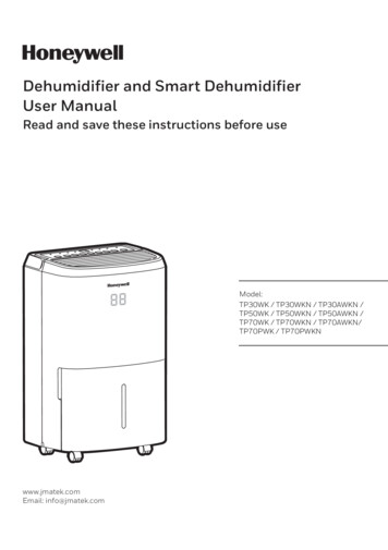
Verifying CapacityIf the unit is functioning properly, and there are no diagnostic codes present, this procedure can be usedif there is concern that the dehumidifier is not removing sufficient moisture. This procedure requiresthat the external static pressure of the dehumidifier be known and that the user has measuringequipment capable of measure air conditions between 50 F – 100 F, and 5% RH to 70% RH. If ductedfrom the return to the supply of the HVAC system, make sure the HVAC system is not operating duringthis test; the HVAC system must be on if the unit is ducted return to return. If the unit is not ducted tothe HVAC system, then it does not matter. Use the graphs and airflow performance tables provided toconvert the inlet/outlet air conditions and airflow to air moisture removal rates. If the inlet airconditions are not within those listed on the table(s), contact Aprilaire Technical Support Mondaythrough Friday from 7:00 a.m. to 5:00 p.m. CST at (800) 334-6011 for assistance in determiningperformance.1. Verify that the flap damper on the outlet of the dehumidifier opens/closes freely.2. Verify that the ductwork is free of obstructions and kinks and that the filter is clean – removethe filter for this test if dirty.3. Ensure that all panels are in place and assembled with screws. DO NOT REMOVE PANELSDURING THIS TEST.4. Adjust the control lowest setting 40% (do not put the unit in TEST mode as this will allow thecompressor to run for only one minute) to initiate a dehumidifier call. Note: If the dew point ofthe air is below 40 F, the dehumidifier compressor will not turn on.5. Measure the static pressure between the inlet and outlet of the dehumidifier and record thecorresponding airflow from the tables below (use an 1830 @ 0.20” w.c. static for example):Table 1: Model 1830Table 2: Model 1850Static Pressure(“w.c.)Airflow (CFM)Static Pressure(“w.c.)Airflow 2006. Allow the dehumidifier to run long enough to get a good, stable reading – 15 minutes minimum.7. Press and hold the MODE button and UP button for 3 seconds. Use the UP or DOWN button toscroll to and record the inlet air temperature (display shows “AIR SAMPLING” along with thevalue) and RH of the inlet air.8. Find the inlet air moisture content in Graph 1 below. Locate the inlet air temperature at thebottom of the graph and draw a straight line up until you meet the inlet air RH curve then readthe moisture content at the left (1.31 ppd/CFM @ 80 , 60% RH for Model 1830 example shown).10 P a g e
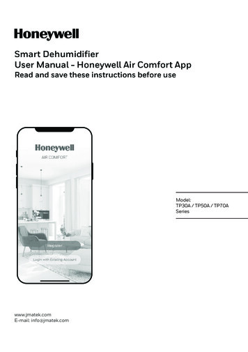
Graph 1Inlet Air Moisture Content1.6570% RHInlet Air Moisture (ppd/CFM)1.5565% RH60% RH1.4555% RH1.3521.2550% RH1.1545% RH1.0540% RH0.950.8510.750.6560657075Inlet Air Temperature ( F)80859. Move a temperature/humidity measuring instrument to the outlet of the dehumidifier.10. Allow time for the measuring instrument to get a good, stable reading.11. Record the outlet air temperature and RH.12. Find the outlet air moisture content in Graph 2 below. Locate the outlet air temperature at thebottom of the curve and draw a straight line up until you meet the outlet air RH curve then readthe moisture content where the two intersect at the left (.72 ppd/CFM @ 115 , 12% RH exampleshown).11 P a g e
Graph 2Outlet Air Moisture Content40%Outlet Air Moisture t Air Temperature ( F)13. Subtract the outlet air moisture content from the inlet air moisture content to determine theamount of moisture being removed by the dehumidifier.EXAMPLE:Measured Static Pressure 0.2”w.c.Airflow from Table 1 or 2 120 CFMInlet Air Temperature 80 FInlet Air %RH 60%Inlet Air Moisture Content (Graph 1) 1.31 ppd/CFMMeasured Outlet Temperature 115 FMeasured Outlet %RH 12%Outlet Air Moisture Content (Graph 2) 0.72 ppd/CFMDehumidifier Capacity (Inlet Air Moisture Content – Outlet Air Moisture Content) * Airflow(1.31 ppd/CFM – 0.72 ppd/CFM)*120 CFM 70ppd12 P a g e
14. Compare the capacity to the approximate performance in the table below. Performance shouldbe within about 20% of the capacity listed below due to the estimation of airflow through theunit:Inlet Air RH60%Inlet Air RH60%6040 ppd1830 CapacityInlet Air Temperature ( F)657050 ppd57 ppd8070 ppd6053 ppd1850 CapacityInlet Air Temperature ( F)657061 ppd73 ppd8095 ppdWORKSHEET:Table 1Table 2Model 1830Model 1850Measured Static Pressure essure(“w.c.)Airflow(CFM)Airflow from Table 1 or 2 0Inlet Air %RH %Inlet Air Moisture Content (Graph 1) ppd/CFMInlet Air Moisture (ppd/CFM)Inlet Air Temperature FGraph 1Moisture Into Dehumidifier 70% RH1.651.551.451.351.251.151.050.950.850.750.6560% RH55% RH50% RH45% RH40% RH6065707580Inlet Air Temperature ( F)13 P a g e65% RH85
Measured Outlet %RH %Outlet Air Moisture Content (Graph 2) ppd/CFMOutlet Air Moisture (ppd/CFM)Measured Outlet Temperature FGraph 2Moisture Discharged by 300.2040%35% 30% 25%20%15%10%75 80 85 90 95 100 105 110 115Outlet Air Temperature ( F)Dehumidifier Capacity (Inlet Air Moisture Content – Outlet Air Moisture Content) * Airflowppd ( ppd/CFM – ppd/CFM)* CFMPerformance should be within about 20% of the capacity listed in the tables below.1830 Capacity1850 CapacityInlet Air Temperature ( F)Inlet Air Temperature ( F)Inlet AirRH606570806065708060%40 ppd 50 ppd 57 ppd 70 ppd53ppd 61ppd 73ppd 95ppdWater LeaksWater collects in the drain pan below the coils and is directed through the drain tube to the outlet at theoutlet side of the dehumidifier.1. Level the unit front to back, and side to side.2. Clean or replace the drain tubing. The drain tubing must have a continual downward slope tothe drain.IMPORTANT: If using ½” vinyl tubing for the drain line, ensure that there are no upward bendsin the tube that could act as a secondary trap – this will cause an air-lock that could prevent theflow of water to the drain.3. Remove the side panel (on the same side as the drain tube); slowly pour a pint of water into thedrain pan near the return bends of the coils. After the running trap fills, the water should flowout the drain tube to the drain.4. Plug or raise the drain tube sufficiently high to prevent water from pouring out of the draintube. Slowly pour in an additional pint of water until the bottom of the drain pan is filled. Allow15-20 minutes for the water to stand in the drain pan and look for any signs of leaks from thedrain pan and drain tube. Unplug the drain and allow the water to drain out.5. Reinstall the side panel.14 P a g e
Fan Does Not Function1. Make sure the outlet the dehumidifier is plugged into is live (120 VAC).2. Turn the User Interfaced Assembly and the ON/OFF toggle switch OFF.3. Remove the side panel and disconnect the blue and yellow fan wires from the Internal Controlboard.4. Inspect the large disk-like component (this is a varistor and it is usually blue or black in color) onthe Internal Control board right next to the fan terminals. If this component looks scorched orcracked, replace the Internal Control board (5444).5. Turn the ON/OFF toggle switch to ON and the User Interface Assembly to ON; the fan shouldstart right away with the display showing “AIR SAMPLING”. Measure the AC voltage at the fanterminals on the Internal Control board. Use caution as this is line voltage. If the FAN LED on the Internal Control board is lit and there is 120 VAC at the fanterminals, disconnect the fan run capacitor and measure the capacitance – this shouldbe 8 µF (microfarad) 5% for the 1830 and 12 µF 5% for the 1850. If the capacitor isbad, replace it (5459 70pt / 5468 95pt); if the capacitor is good then replace the fanFan Capacitor(5453 70pt / 5467 95pt). 15 P a g eIf the FAN LED on the Internal Control board is lit and there is 0 VAC, the InternalControl board will need to be replaced (5444).If the FAN LED on the Internal Control board is not lit and the display shows “AIRSAMPLING”, the User Interface Assembly will need to be replaced (5445).
Circuit Breaker TripsThe 1830 and 1850 must be plugged into an outlet served by a 15 amp circuit breaker. The 1850dehumidifier uses approximately 8 amps at high load (i.e. hot and humid) conditions and less at low loadconditions. The 1830 dehumidifier uses approximately 6 amps at high load and less at low load.If there are other electrical components that draw a lot of current connected to the same circuitbreaker, the circuit may be overloaded and a new circuit should be run to serve the dehumidifier.Consult with a qualified electrical contractor if there are questions as to the suitability of the circuit intowhich the dehumidifier is plugged.If the electrical service is sound, there are two primary reasons why a circuit breaker would trip: a wirehas disconnected or the compressor run capacitor is faulty.1.Turn the ON/OFF toggle switch OFF, unplug the dehumidifier, and remove the side panel fromthe dehumidifier.2. Inspect the electrical connections at the power switch, Internal Control board and runcapacitors.3. If none of the wires have been disconnected, remove the wires connected to the run capacitor.4. Measure the capacitance of the compressor run capacitor, it should be 45 µF (microfarad) 5%.16 P a g e
1830/1850 Parts ListNo.Part DescriptionPart No.No.Part DescriptionPart No.11Fan, 70pt5453Fan, 95pt54671Filter 10” x 12” x 1” EZK54432Internal Control Board54443User Interface Assembly544512Wire Harness, Power54544Wiring Access Door544613Sensor, Low Temperature54555Hole Cover, UI Ctrl544714Sensor, High Temperature54566Door, Filter Access544815Leveling Foot54577Outlet Duct Panel544916Capacitor, 45MFD, 370VAC, 70pt/95pt54588Backflow Damper, 10”545017Capacitor, 8MFD, 450VAC, 70pt54599Inlet Duct Panel5451Capacitor, 12MFD, 450VAC, 95pt546810Cover, Outlet545218RH Sensor546019Drain Tube Fittings5461Compressor Overload Switch, 70pt5547Compressor Overload Switch, 95pt5548NotShown17 P a g e
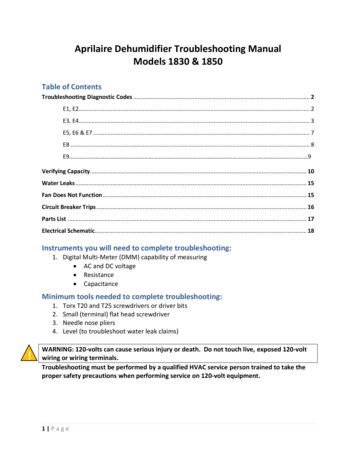
DISPLAY BOARDTRANSFORMERSENSOR BOARDINTERNALCONTROLBOARDHIGH TEMP SENSORFROST SENSORCOMPRESSORCOMPRESSORRUN CAPACITOR1830 & 1850 Wiring SchematicFAN RUNCAPACITORFAN18 P a g e
1. If ducting to the HVAC system, make sure the inlet to the dehumidifier is not ducted to the supply side of the HVAC system. 2. Attic installations - Inspect the ductwork attached to the inlet of the dehumidifier for leaks if the ambient temperature is high. 3. Ventilation applications - High temperatures may be offset by mixing air from the