Transcription
M&C 2017 - International Conference on Mathematics & Computational Methods Applied to Nuclear Science & Engineering,Jeju, Korea, April 16-20, 2017, on USB (2017)MC21 / CTF and VERA Multiphysics Solutions to VERA Core Physics Benchmark Progression Problems 6 and 7Daniel J. Kelly IIIa,*, Ann E. Kellya, Brian N. AvilesaAndrew T. Godfreyb, Robert K. Salkob, Benjamin S. CollinsbaNaval Nuclear Laboratory, Knolls Atomic Power Laboratory, Schenectady, NY 12301, USA *daniel.kelly@unnpp.govbOak Ridge National Laboratory, 1 Bethel Valley Road, Oak Ridge, TN, 37831, USAAbstract – The continuous energy Monte Carlo neutron transport code, MC21, was coupled to the CTFsubchannel thermal-hydraulics code using a combination of CASL tools and in-house Python scripts. AnMC21/CTF solution for VERA Core Physics Benchmark Progression Problem 6 demonstrated excellentagreement with MC21/COBRA-IE and VERA solutions. The MC21/CTF solution for VERA Core PhysicsBenchmark Progression Problem 7, Watts Bar Unit 1 at beginning of cycle (BOC) hot full power (HFP)equilibrium xenon conditions, is the first published coupled Monte Carlo neutronics / subchannel T-Hsolution for this problem. MC21/CTF predicted a critical boron concentration of 854.5 ppm, yielding acritical eigenvalue of 0.99994 6.8E-6 (95% CI). Excellent agreement with a VERA solution of Problem 7was also demonstrated for integral and local power and temperature parameters.I. INTRODUCTIONMonte Carlo reactor physics codes coupled withsubchannel thermal-hydraulics (T-H) codes are becomingmore common for the solution of large-scale nuclear reactorproblems [1, 2]. These complement the growing number ofcoupled deterministic transport reactor physics / subchannelT-H codes applied to similar systems-level reactorproblems. This paper describes the coupling of thecontinuous energy Monte Carlo code, MC21 [3], to thesubchannel T-H code, CTF [4], which is part of theConsortium for Advanced Simulation of Light WaterReactor’s (CASL) Virtual Environment for ReactorApplications (VERA) code system [5, 6]. MC21/CTFsolutions for CASL VERA Core Physics BenchmarkProgression Problems 6 and 7 [7] are presented andcompared to VERA solutions (MPACT coupled to CTF) ofthe same benchmark problems.II. MC21 / CTF COUPLINGPrevious work reported the coupling of MC21 andCOBRA-IE [8] for the analysis of a hot-full-power (HFP)Pressurized Water Reactor (PWR) assembly [9]. COBRAIE and CTF share a common COBRA ancestor but havebeen developed separately. Because CTF is the subchannelT-H code in VERA, it is desirable to couple MC21 and CTFto fully separate differences between neutronics and T-Heffects. In this work, MC21 is coupled to CTF using acombination of modules from VERA and in-house Pythonscripts, as shown in Fig. 1 through Fig. 3 and describedbelow.Input processing for VERA is performed using theVERAIn common input parser and VERA processing tools[10] (Fig. 1) to generate CTF model input and geometryinformation needed to map results between MC21 and CTF.CTF input is generated for the complete model using thatVERA input file. Although this section describes theProblem 7 benchmark, a ¼-core model of Watts Bar Unit 1,the Problem 6 benchmark model with a single assembly(and single CTF input / output file) was also run using thesame process with different input arguments.The MC21 model input file is processed with thePhysics Unified Modeling and Analysis (PUMA) system,which generates all necessary input files for MC21execution (Fig. 2). PUMA and MC21 are part of theCommon Monte Carlo Design Tool (CMCDT) project at theNaval Nuclear Laboratory [3,11]. MC21 is executed initiallywith isothermal T-H conditions.With MC21 and CTF model initialization complete, aconverged mutually-consistent neutronics and T-H solutionis performed via Picard iteration (Fig. 3). First, the in-housemc21 to ctf.py script combines geometry informationfrom the CTF model with fission tallies and additional jobinformation from MC21 to compute relative linear heat ratedistributions for each assembly. The process utilizes theCTF HDF5 pdeck.h5 file and the power distributioninformation is written to the “pin powers” data set in thatfile in the correct assembly locations. Second, CTF is thenexecuted using the multistate cobra external driverprogram [12] and the newly generated pdeck.h5 filecontaining the MC21 power distributions, as well as theCTF model generated from the VERAin file. Third,subchannel temperatures and densities, and fuel rod volumeaverage temperatures are collected from the CTF HDF5output by the in-house ctf to mc21.py script andtranslated back to the proper MC21 regions. Thesetemperatures and densities are saved in an MC21 HDF5 filethat will be imported in the next execution of MC21. Fourth,MC21 is executed with updated T-H conditions. The Picarditeration in Fig. 3 is repeated until convergence is achieved.
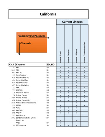
M&C 2017 - International Conference on Mathematics & Computational Methods Applied to Nuclear Science & Engineering,Jeju, Korea, April 16-20, 2017, on USB (2017)Fig. 1. VERAIn / CTF Pre-Processing Flowchart (Blue VERA codes and files)Fig. 3. MC21 / CTF Picard Iteration Flowchart (Blue VERA codes and files, Green CMCDT codes and files,Magenta in-house scripts), dashed lines files generatedin preprocessing stepsIII. MODEL DESCRIPTIONFig. 2. MC21 Pre-Processing and Initial Isothermal Job(Green CMCDT codes and files)The MC21 model was generated using the PUMAmodel builder which is part of the CMCDT project [11].PUMA input is based on a Java input deck which easilyenables the user to build complicated geometries usingbuilt-in methods in addition to the many features of the Javaprogramming language. Specifications of the VERAbenchmark problems are taken from [7]. New to this work isthe restructuring of the PUMA model to more easilyfacilitate the construction of MC21 models based on theVERA common input file [10]. Building MC21 models withthis format simplifies model construction as well asenhances model quality assurance by enabling direct modelinput comparisons between the corresponding VERA andPUMA/MC21 models. For PUMA to support this type offormat, a separate Java class (VERA-Util) was written tohandle model construction. At this stage of development,the various VERA input cards such as cell, lattice, axial,and assm map (to name a few) are reformatted to workwithin the PUMA framework. Ideally, a PUMA translator
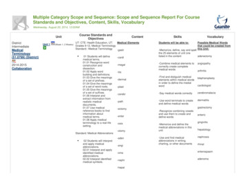
M&C 2017 - International Conference on Mathematics & Computational Methods Applied to Nuclear Science & Engineering,Jeju, Korea, April 16-20, 2017, on USB (2017)would read these cards directly. For both VERA BenchmarkProblems 6 and 7, the 2D lattices were constructed usingoctant-symmetry. The corresponding VERA input files areavailable from CASL.An example extracted from the PUMA input file toconstruct a pin cell and corresponding fuel lattice is shownbelow.TFB SubchannelFigure f1 VERAUtil.makePinCell("F1","0.4096 0.418 0.475 / u21 he zirc4");This line describes the various concentric rings as well asthe materials to be assigned to each region. The portion ofcode that specifies input required to construct a fuel latticein PUMA using octant symmetry with the VERAUtil classis show below.Figure[] fig26 {g4,f1, f1,f1, f1, f1,g4, f1, f1,f1, f1, f1,f1, f1, f1,g4, f1, f1,f1, f1, f1,f1, f1, f1,g4,f1,f1,g4,f1,f1,f1,f1,f1,f1,f1,g4,f1, f1,f1, f1, f1,f1, f1, f1, f1};Overlay lat26 VERAUtil.makeLattice("LAT26",fig26)In a standard MC21 PUMA model, each unit cell isconstructed from five regions consisting of two squares (theouter square is either spacer grid material or coolant and theinner square is subchannel coolant) and three concentriccircles (clad, gap, and fuel). For a thermal-hydraulicfeedback (TFB) model, 11 regions are required since thegrid and coolant regions are each subdivided into quadrants(Fig. 4). In addition, the TFB case requires that therespective quadrant from one pin cell share a common“attribute” with the adjoining quadrants in the neighboringpin cell so that a compatible sub-channel is defined tointerface with the CTF model (Fig. 5). Fuel pins arespecified as a complete pin and a separate attribute isassigned to these regions.Standard ModelTFB ModelFig. 4. MC21 PUMA Description of Pin Cell GeometryFig. 5. MC21 PUMA Description of Subchannel GeometryThe “attribute” mentioned above is a powerful featureof PUMA where specific properties, called attributes, canbe assigned to geometric figures during model creation suchthat a specific set of figures can be grouped together for thepurpose of edits and/or material assignments. As part of theinternal temperature feedback capabilities of MC21 [3],specific attributes called “source” and “sink” are used tospecify power generating regions (sources) and coolantregions (sinks). In the MC21 input files, specific input isgiven for these two attributes in addition to the standardregion id and material id. In addition, the temperaturefeedback capability of MC21 specifies a unique file formatwhereby the user can specify the temperature of the sources(i.e., fuel pins) and both the temperature and density of thesinks (i.e., coolant regions) to achieve the effects oftemperature feedback on MC21 material number densitiesand cross sections. These input files and features of MC21and PUMA allow MC21 to be coupled to external T-Hcodes such as CTF.IV. RESULTS1. VERA Core Physics Benchmark Problem 6VERA Core Physics Benchmark Problem 6 is a PWRfuel assembly at HFP conditions [7]. Problem 6 wassimulated without guide tube heating using MC21/CTF todemonstrate that coupling of MC21 and CTF using theprocess described in Section II was working properly.MC21/CTF results are compared with updatedMC21/COBRA-IE and VERA solutions from [9]. TheMC21 and CTF assembly geometry is described in [7, 9].MC21 uses cross sections from ENDF/B-VII.1, with nonwater material cross sections ranging from 500 K to 1600 Kin 50 K increments up to 900 K and 100 K incrementsthereafter, and water cross sections ranging from 500 K to650 K at 10 K intervals. MPACT employs a 51 energygroup cross section library based on ENDF/B-VII.1 datawith subgroup parameters to capture self-shielding effects.Nine coupled iterations were simulated to convergeMC21 and CTF. Fig. 6 presents the MC21 eigenvaluetrajectory during the nine data exchanges. The number ofactive neutron histories for each data exchange is shown on
M&C 2017 - International Conference on Mathematics & Computational Methods Applied to Nuclear Science & Engineering,Jeju, Korea, April 16-20, 2017, on USB (2017)the right axis and increases from 200 million histories at thefirst data exchange to 2 billion histories for data exchanges5 through 9 (200 active generations of 10 million neutronsper generation preceded by 50 discarded generations). Twobillion histories were adequate to reduce uncertainties inlocal pin power 0.7% [9]. The MC21 eigenvalue isconverged at data exchange 5 when the two billion activeneutron history value is reached.1.164402.01.16435MC21 5MC21 Eigenvalue1.16400Active Neutron Histories1.163950.5Active Histories (Billion Neutrons)1.16430Fig. 7. CTF Convergence Metrics for Subchannel CoolantTemperature during MC21/CTF Data CTF Data Exchange IndexFig. 6. MC21 Eigenvalue and Number of Active NeutronHistories during MC21/CTF Data ExchangesLocal subchannel coolant temperature, average fuel rodtemperature, and pin linear heat rate convergence metrics, asmeasured by the L2 and L norms with respect to theirrespective final (exchange index 9) distributions, arepresented in Fig. 7 – Fig. 9. As was done in [9], the L2 normfor coolant temperature was normalized by the square rootof the number of subchannel regions (4410), and the L2norms for fuel temperature and pin linear heat rate werenormalized by the square root of the number of fuel regions(3528). These norms also indicate that the coupledMC21/CTF solution is converged at data exchange 5, aslocal coolant temperatures are within 0.02 C, local fueltemperatures are within 3 C, and local pin linear heat ratesare within 2 W/cm of their final data exchange values,respectively.Table I presents calculated eigenvalues for the threecode systems. MC21/CTF and MC21/COBRA-IE producestatistically-equivalent eigenvalues.Table I. Calculated Eigenvalues for CASL P6 ¼-AssemblyCode SystemEigenvalueDifference(95% CI)(pcm)MC21/COBRA-IE 1.16424 (2.6E-05)ReferenceMC21/CTF1.16424 (2.6E-05)0MPACT/CTF1.16361-63Fig. 8. CTF Convergence Metrics for Fuel Temperatureduring MC21/CTF Data ExchangesFig. 9. CTF Convergence Metrics for Pin Linear Heat Rateduring MC21/CTF Data ExchangesFig. 10 presents axially-integrated ¼-assemblynormalized pin fission rates, and Fig. 11 presentssubchannel exit coolant temperatures for all three code
M&C 2017 - International Conference on Mathematics & Computational Methods Applied to Nuclear Science & Engineering,Jeju, Korea, April 16-20, 2017, on USB (2017)systems. MC21/CTF produces results nearly identical toMC21/COBRA-IE and consistent with VERA, indicatingexcellent agreement between MC21 and MPACT powerdistributions and COBRA-IE and CTF T-H solutions forthis ¼-assembly HFP benchmark problem. Focusing onMC21/CTF comparisons with VERA, the maximumdifferences in axially-integrated pin power are -0.19% in pin(9,10) and 0.17% in pin (13,13) with a root mean square(RMS) difference of 0.09%. Subchannel exit coolanttemperatures agree within 0.1 C with an RMS differenceof 0.02 0.93850.93880.94000.94230.94220.94300.9768 MC21/CTF0.9767 MC21/COBRA-IE0.9762 VERA0.97250.97260.9725Color ies for MC21 and MPACT for Problem 7 are identicalto Problem 6, as described in Section IV.1. In this analysis,all central instrument tubes were replaced with guide tubesto enable ¼-core symmetry. Instrument tubes will bereinstated when future comparisons with flux maps areperformed. A reactivity sensitivity study of replacinginstrument tubes with guide tubes was performed withVERA, indicating that guide tubes are worth 4 ppm ofboron ( 40 pcm).MPACT was executed using the 2D/1D technique withtransport-corrected P0 2D MOC in the radial planes and SP3in the axial direction. Temperature and density changes aremonitored to determine if the subgroup calculation needs tobe re-executed to obtain new shielding parameters for crosssection generation.Fig. 10. Axially-Integrated ¼-Assembly Normalized PinFission Rate Comparison, VERA Problem 8325.1326.1325.1323.3323.4323.4325.0 MC21/CTF (C)324.7 MC21/COBRA-IE (C)325.0 VERA 5.5324.8324.6324.4330.0324.6324.3324.1324.3Guide Tube 1.9Fig. 11. Subchannel Exit Coolant Temperature Comparison,VERA Problem 62. VERA Core Physics Benchmark Problem 7VERA Core Physics Benchmark Problem 7 representsWatts Bar Nuclear Unit 1 at Beginning-of-Cycle (BOC),HFP, equilibrium xenon conditions [7], with different fuelenrichments of 2.11% (red), 2.619% (green), and 3.10%(blue), respectively, as shown in Fig. 12. The cross sectionFig. 12. PUMA Visualization of ¼-Core MC21 Model forVERA Problem 7A. MC21/CTF Running StrategyMC21 was executed using the critical boron searchfeature of MC21 at equilibrium xenon conditions with fullthermal-hydraulic feedback using fuel and coolanttemperatures and coolant densities from CTF. Table IIdescribes the running strategy and results for MC21/CTFduring the five Picard iterations. The goal was to computecritical boron such that MC21’s eigenvalue was within 10pcm of unity. Critical boron searches were performed initerations 2 and 3. The critical boron concentration searchrange for MC21 was set from 700 ppm to 900 ppm, andMC21 automatically performs partial spatial solutions untilthe eigenvalue is within a user-specified tolerance ( 10 pcmin this study), at which time MC21 performs a full spatialsolution. Equilibrium xenon was updated every five
M&C 2017 - International Conference on Mathematics & Computational Methods Applied to Nuclear Science & Engineering,Jeju, Korea, April 16-20, 2017, on USB (2017)generations (user specified). Note that in iteration 4, as thenumber of active histories increased, the more tightlyconverged power solution affected the temperaturedistributions and caused the calculated eigenvalue to strayoutside the 10 pcm target set by the earlier critical boronsearches. Based on MC21’s estimate of boron sensitivityfrom these earlier iterations ( 10.3 pcm/ppm), boronconcentration was re-adjusted prior to iteration 5. Iteration 5was then executed as a restart from the iteration 4 solutionwith 30 billion active neutron histories (7500 activegenerations of 4 million neutrons / generation, 50 discardedgenerations) with the goal of driving the uncertainty on localpin power to 2%, based on [11]. No variance reductiontechniques were employed in this study. For the 5th Picarditeration, MC21 required 164 wall clock hours (6.8 days)using 32 nodes containing two 16-core Intel Xeon E52683v4 2.1GHz (Broadwell) processors (1024 total cores).VERA execution took 57 minutes using 464 cores on IdahoNational Laboratory’s Falcon computer (Intel Xeon E52680v3 2.5GHz processors).2345Fixed Boron,Isothermal,eqXeBoron Search,T/H Feedback,eqXeBoron Search,T/H Feedback,eqXeFixed Boron,T/H Feedback,eqXeFixed Boron,T/H Feedback,eqXe1.01133(1.8E-4)100 million(1 million)0.99989(1.2E-4)100 million(1 million)1.00003(1.0E-4)852.3500 million(1 million)1.00031(4.8E-5)854.530 billion(4 million)0.99994(6.8E-6)859.7852.399.9% 100.0%85.2%70%kcalc(95% CI)50 million(500,000)900.098.1% 99.4% 99.7%94.4%90%80%size)1100%B. Select M
programming language. Specifications of the VERA benchmark problems are taken from [7]. New to this work is the restructuring of the PUMA model to more easily MC21 models based on the VERA common input file [10]. Bui