Transcription
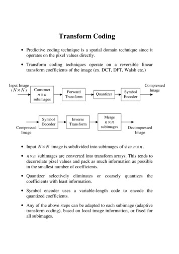
Transform Coding Predictive coding technique is a spatial domain technique since itoperates on the pixel values directly. Transform coding techniques operate on a reversible lineartransform coefficients of the image (ex. DCT, DFT, Walsh etc.)Input Image(N N )Constructn edImageMergen nsubimagesDecompressedImage Input N N image is subdivided into subimages of size n n . n n subimages are converted into transform arrays. This tends todecorrelate pixel values and pack as much information as possiblein the smallest number of coefficients. Quantizer selectively eliminates or coarsely quantizes thecoefficients with least information. Symbol encoder uses a variable-length code to encode thequantized coefficients. Any of the above steps can be adapted to each subimage (adaptivetransform coding), based on local image information, or fixed forall subimages.
Walsh Transform (1-D case) Givenaf (m), m 0,1,is defined as:1W (u ) None-dimensionalimage(sequence)q, N 1, with N 2 , its Walsh transform W (u ) f (m) ( 1)q 1N 1m 0bi ( m ) bq 1 i ( u ), u 0,1,, N 1. i 0bk ( z ) : k th bit (from LSB) in the binary representation of z. Note that the Walsh-Hadamard transform discussed in the text isvery similar to the Walsh transform defined above. Example: Suppose z 6 110 in binary representation. Thenb0 (6) 0 , b1 (6) 1 and b2 (6) 1. The inverse Walsh transform of W (u ) is given byf (m) W (u ) ( 1)q 1N 1u 0bi ( m ) bq 1 i ( u ), m 0,1, , N 1.i 0 Verify that the “inverse works.” Let g ( m) N 11N u 0 f (n) ( 1)N 1n 0q 1 q 1 ( 1)bi ( n ) bq 1 i ( u ) i 0 i 0 This is W ( u ) with m replaced with n.1 N f (n) ( 1)N 1N 1 q 1n 0u 0 i 0(bi ( n ) bi ( m ) )bq 1 i ( u )? f (m)(HW problem!!)bi ( m ) bq 1 i ( u )
Walsh Transform (2-D case) Given a two-dimensional N N image f (m, n) , with N 2q , itsWalsh transform W (u , v) is defined as:1W (u , v) Nu , v 0,1, , N 1. f (m, n) ( 1)N 1 N 1q 1m 0 n 0i 0bi ( m ) bq 1 i ( u ) bi ( n ) bq 1 i ( v ), Similarly, the inverse Walsh transform is given by1f (m, n) Nm, n 0,1, , N 1. W (u, v) ( 1)N 1 N 1u 0 v 0q 1bi ( m ) bq 1 i ( u ) bi ( n ) bq 1 i ( v ),i 0 The Walsh transform is Separable (can perform 2-D transform in terms of 1-Dtransform).Symmetric (the operations on the variables m, n are identical).Forward and inverse transforms are identical.Involves no trigonometric functions (just 1 and –1), so iscomputationally simpler.
Discrete Cosine Transform (DCT) Given a two-dimensional N N image f (m, n) , its discretecosine transform (DCT) C (u , v) is defined as:C (u, v ) α (u )α (v)N 1 N 1f (m, n) cos m 0 n 0u , v 0,1, , N 1, whereα(u ) 1N 2N(2m 1)uπ ( 2n 1) vπ cos ,2N2N , u 0, u 1,2,, N 1 Similarly, the inverse discrete cosine transform (IDCT) is givenbyf (m, n) N 1 N 1α (u )α (v)C (u, v) cos u 0 v 0(2m 1)uπ ( 2 n 1)vπ cos ,2N2N m, n 0,1, , N 1. The DCT is Separable (can perform 2-D transform in terms of 1-Dtransform).Symmetric (the operations on the variables m, n are identical)Forward and inverse transforms are identical The DCT is the most popular transform for image compressionalgorithms like JPEG (still images), MPEG (motion pictures). The more recent JPEG2000 standard uses wavelet transformsinstead of DCT. We will now look at a simple example of image compression usingDCT. We will come back to this in detail later.
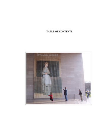
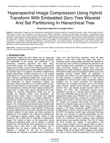
Discrete Cosine Transform ExampleOriginal ImageFraction of DCT coeff. Used 0.65,MSE: 1.6Fraction of DCT coeff. Used 0.85,MSE: 0.45Fraction of DCT coeff. Used 0.41,MSE: 4
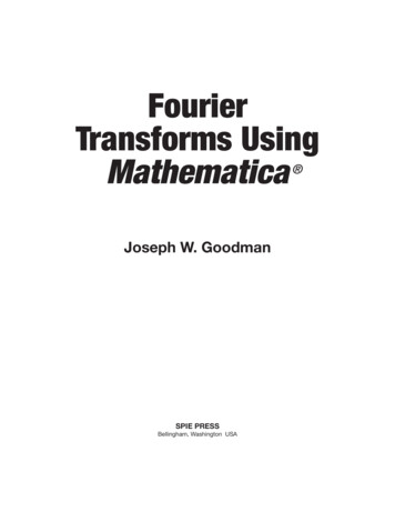
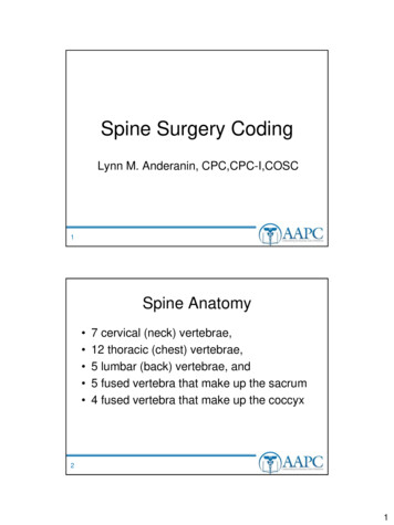
Discrete Cosine Transform ExampleFraction of DCT coeff. Used 0.19,MSE: 7.7Fraction of DCT coeff. Used 0.08,MSE: 12
Transform Selection Commonly used ones are Karhunen-Loeve (Hotelling) transform(KLT), discrete cosine transform (DCT), discrete Fouriertransform (DFT), Walsh-Hadamard transform (WHT). Choice depends on the computational resources available and thereconstruction error that can be tolerated. This step by itself is lossless and does not lead to compression. Thequantization of the resulting coefficients results in compression. The KLT is optimum in terms of packing the most information forany given fixed number of coefficients. However, the KLT is data dependent. Computing it requirescomputing the correlation matrix of the image pixel values. The “non-sinusoidal” transforms like the WHT are easy tocompute and implement (no multiplications and no trigonometricfunction evaluation). Performance of “sinusoidal” transforms like DCT, DFT, in termsof information packing capability, closely approximates that of theKLT. DCT is by far the most popular choice and is used in the JPEG(Joint Photographic Experts Group) image standard.
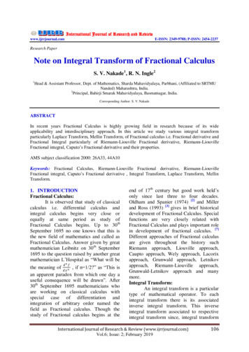
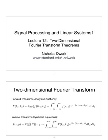
Reconstructed ImageError ImageDCTRMSE 0.018DFTRMSE 0.028WHTRMSE 0.023DCT/DFT/WHT comparison for 8 8 subimages, 25% coefficients(with largest magnitude) retained. Note also the blocking artifact.
Subimage Size Selection Images are subdivided into subimages of size n n to reduce thecorrelation (redundancy) between adjacent subimages. Usually n 2k , for some integer k. This simplifies the computationof the transforms (ex. FFT algorithm). Typical block sizes used in practice are 8 8 and 16 16 .Comparison of different transforms and block sizes for transform oN0.0260.0240.0220.020.0180.016110Size of subimage
Bit Allocation After transforming each subimage, only a fraction of thecoefficients are retained. This can be done in two ways:Zonal coding: Transform coefficients with large variance areretained. Same set of coefficients retained in all subimages.Threshold coding: Transform coefficients with largemagnitude in each subimage are retained. Different set ofcoefficients retained in different subimages. The retained coefficients are quantized and then encoded. The overall process of truncating, quantizing, and coding thetransformed coefficients of the subimage is called bit-allocation.
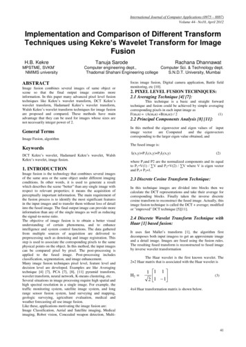
Reconstructed ImageError ImageRMSE 0.029Threshold codingRMSE 0.038Zonal codingComparison of Zonal and Threshold coding for 8 8 DCT subimages,with 12.5% coefficients retained in each case.
Zonal Coding: Transform coefficients with large variance carry most of theinformation about the image. Hence a fraction of the coefficientswith the largest variance is retained. The variance of each coefficient is calculated based on theensemble of ( N / n) 2 transformed subimages, or using a statisticalimage model. Recall Project #2 on DCT. The coefficients with maximum variance are usually locatedaround the origin of an image transform. This is usuallyrepresented as a 0-1 mask. The same set of coefficients are retained in each subimage. The retained coefficients are then quantized and coded. Twopossible ways:The retained coefficients are normalized with respect to theirstandard deviation and they are all allocated the same number ofbits. A uniform quantizer then used.A fixed number of bits is distributed among all the coefficients(based on their relative importance). An optimal quantizer suchas a Lloyd-Max quantizer is designed for each coefficient.
Threshold Coding: In each subimage, the transform coefficients of largest magnitudecontribute most significantly and are therefore retained. A different set of coefficients is retained in each subimage. So thisis an adaptive transform coding technique. The thresholding can be represented as T (u, v)m(u, v) , wherem(u , v ) is a masking function:m(u, v ) 0 if T (u , v) satisfies some truncation criterion1otherwise The elements of T (u, v)m(u, v) are reordered in a predefinedmanner to form a 1-D sequence of length n 2 . This sequence hasseveral long runs of zeros, which are run-length encoded.1 1 1 0 1 0 0 01 1 1 0 0 0 0 01 1 0 0 0 0 0 01 0 0 0 0 0 0 01 0 0 0 0 0 0 00 0 1 0 0 0 0 00 0 0 0 0 0 0 00 0 0 0 0 0 0 0Typical threshold 555962Zigzag ordering of coefficients2842435354606163
The retained coefficients are encoded using a suitable variablelength code. The thresholding itself can be done in three different ways,depending on the “truncation criterion:”A single global threshold is applied to all subimages. The levelof compression differs from image to image depending on thenumber of coefficients that exceed the threshold.N-largest coding: The largest N coefficients are retained ineach subimage. Therefore, a different threshold is used for eachsubimage. The resulting code rate (total # of bits required) isfixed and known in advance.Threshold is varied as a function of the location of eachcoefficient in the subimage. This results in a variable code rate(compression ratio). Here, the thresholding and quantization steps can be togetherrepresented as:OriginalTransformcoefficient Thresholdedand quantizedvalueT (u, v)Tˆ (u, v ) roundZ (u, v) NormalizationFactor
Z(u, v) is a transform normalization matrix. Typical exampleis shown 789516 24 4019 26 5824 40 5729 51 8756 68 10964 81 10487 103 12198 112 10051 6160 5569 5680 62103 77113 92120 101103 99The values in the Z matrix weigh the transform coefficientsaccording to heuristically determined perceptual or psychovisual importance. Larger the value of Z(u, v), smaller theimportance of that coefficient.The Z matrix maybe scaled to obtain different levels ofcompression.At the decoding end, T (u, v) Tˆ (u, v) Z (u, v ) is used todenormalize the transform coefficients before inversetransformation.
Example: Coding with different ZReconstructed ImageError ImageRMSE 0.023Quantization matrix Z(9152 non-zero coefficients)RMSE 0.048Quantization matrix 8Z(2389 nonzero coefficients)
Transform Coding Predictive coding technique is a spatial domain technique since it operates on the pixel values directly. Transform coding techniques operate on a reversible linear transform coefficients of the image (ex. DCT, DFT, Walsh etc.) I Input N N image is subdivided into subimages of size n n.