Transcription
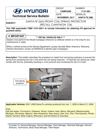
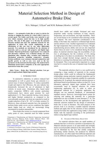
DESIGN AND SELECTION OFPLASTIC PRESSURE PIPETECHNICAL BULLETIN1.INTRODUCTIONPotable water pressure pipes are made from many different materials. The most commonly used pipe materials formunicipal water systems are polyvinyl chloride (PVC), ductile iron (DI), high density polyethylene (HDPE), steel (ST)and concrete pressure pipe (CPP). Selecting the right pipe material and the right class of that material, requires anunderstanding of the system operating conditions and the strengths and weaknesses of each material.Replacement of current infrastructure piping is estimated to cost billions of dollars. The average age of pipes currentlybeing replaced is about 50 years. Plastic pipes offer high reliability and excellent performance during their service lifewhich is estimated to be at least 100 years if the correct class of pipe is used. It is responsibility of designers toconsider the life expectancy of plastic pipe when selecting the pipe material for projects funded from public sources.2.PIPE PRESSURE CLASSThe steady state Pressure Class (PC) of a thermoplastic pipe is a function of the allowable hoop stress and the pipewall thickness. It is calculated in accordance with the ISO equation:𝑃𝐶 2 𝑥 𝐻𝐷𝑆𝐷𝑅 1HDS Hydrostatic design stress for water at 73 F, psiDR Dimension Ratio 𝑃𝑖𝑝𝑒 𝑂𝑢𝑡𝑠𝑖𝑑𝑒 ��𝑢𝑚 𝑊𝑎𝑙𝑙 𝑇ℎ𝑖𝑐𝑘𝑛𝑒𝑠𝑠 𝑂𝐷𝑡𝑚𝑖𝑛PVC and HDPE / Pipe Pressure Class ( Example)160DR26PVCPressure Class80200DR21100050100Pressure (psi)150200HDPEPressure Class250The designer cannot select which pipe (material) to use simply by specifying a pressure class (PC) for theapplication. There are pressure fluctuations in the system resulting from events such as pump start-up or shut-downand valves opening and closing.Technical Service Bulletin 1
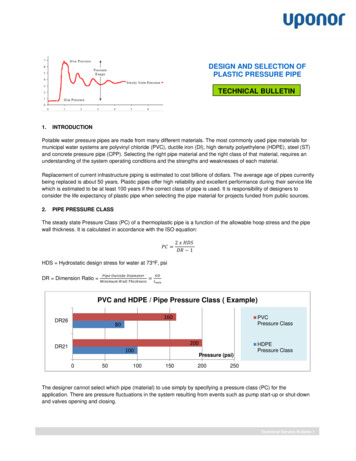
The pressure profile in a pipe due to dynamic system changes in flow velocity is so material property dependent, thatthere is no obvious simple way for pipes of different materials to have ‘the same’ pressure class. The difference in theability of pipes of different materials to handle pressures caused by dynamic events means that PC alone cannot bethe basis for the pipe selection.HDPE Pipe:The pressure class of a polyethylene pipe includes an allowance for surge pressures. The allowance for recurringsurge pressures (regular valve and pump operation) is 50% of the pressure class. For occasional surge pressures(unanticipated system failures), the allowance is 100% the pressure class.HDPE Pipe200DR21Allowable TotalPressure DuringOccasional Surge150100250DR17188125Allowable TotalPressure DuringRecurring Surge320DR13.5240160Pressure Class400DR113002000100200Pressure (psi)300400500PVC Pipe:PVC pipe excludes any allowances for recurring surge pressure. The allowance for occasional surge pressures is60% of the pipe’s pressure class (PC). The user is required to calculate the magnitude of the peak surge anticipatedand to ensure that the pressure class of the pipe exceeds the working pressure plus the surge pressure.Technical Service Bulletin 2
3.PRESSURE SURGESurge pressures (also known as water hammer, hydraulic transients) in liquid transmission systems are caused bysudden changes in the velocity of the fluid flowing in the pipe, which can be produced by valves operating, pumpstart/stops, power failures, and other operations.Pressure surges are generally classified as Occasional and Recurring. Occasional surge pressure is the result of an infrequent event and is usually the result of a malfunction, suchas a power failure or system component failure (such as, pump seize-up, valve-stem failure and pressurerelief valve failure). Recurring surge pressures occur frequently and are inherent in the design and operation of the pipingsystem (such as, normal pump start-up or shut-down and normal valve opening and closing).The analysis to determine the magnitude of a pressure surge is based on a full flow stoppage at the maximum flowvelocity (Joukowsky equation) and provides a good basis for evaluating surge events considering the range of serviceconditions that may occur during the life of the pipe. Both AWWA M55 PE Pipe—Design and Installation andAWWA M23 PVC Pipe—Design and Installation employ this type of analysis method.The magnitude of the pressure surge caused by sudden changes in the velocity of the flow in a pipe is a function ofthe change in velocity, the stiffness (modulus) of the pipe, and the resistance to compression (bulk modulus) of theflowing fluid.𝛥𝑣𝑃𝑠 𝑎()2.31𝑔Ps surge (psi)Δv change in velocity (ft/s)g acceleration due to gravity ( 32 ft/sec²)a wave velocity (ft/s)𝑎 4660 1 𝐾𝑏𝑢𝑙𝑘(𝐷𝑅 2)𝐸𝑑Kbulk fluid bulk modulus, (300,000 psi for water at 73 F)Ed Dynamic instantaneous effective modulus of pipe material, (150,000 psi for HDPE, 400,000 psi for PVC)DR dimension ratioTechnical Service Bulletin 3
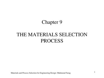
Since the fluid being conveyed is usually water, the only variables are the modulus of the pipe and the design flowvelocity.The design flow velocity used to determine surge pressures can usually be found in Municipal design standards forwater distribution systems.A survey of fifty-seven municipalities in North America (mostly US) for Jana’s Technical Report on Fatigue ofPlastic Water Pipe indicates that the average flow velocity for normal flow is 6.7 ft/s ( 2 m/s) and for fire flow is 11.6ft/s ( 3.5 m/s). The AWWA Water Distribution Operator Training Handbook suggests 5 ft/s (1.5 m/s) as a typicallimit for normal operations with higher velocities expected during fire flow conditions.A sampling of design flow guidance of Canadians municipalities suggest that the maximum velocity for normal flow inthe pipe shall not exceed 5 ft/s ( 1.5 m/s) and for fire flow about 8 ft/s (2.4 m/s) to 16.2 fps (5 m/s).Example: Working Pressure and Surge Assessment of 12” DIPS DR18 PVC pipe and 12” DIPS DR17 PE4710 HDPEpipe.Dimensional Information:12” DIPS DR17 HDPE12” DIPS DR18 PVCPipe OD (in)13.2013.20Pipe ID (in)11.5511.65Bore Area (sq.in)0.730.74The manufacturer’s published pressure class for a PVC DR18 pipe is 235 psi. This rating does not include allowancefor recurring surge pressures that might occur. The designer is first required to determine the magnitude of themaximum surge pressure. The working pressure plus the surge pressure shall not exceed the pressure class of thepipe.12" DIPS DR18 PVC Pipe / Working Pressure Rating10619798Velocity (ft/s)174156967139113613151041484Working Pressure Rating122871653701832Surge Pressure52200135218 170255075100 125 150Pressure (psi)175200225250Technical Service Bulletin 4
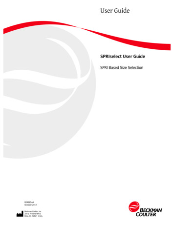
Stopping a flow that had a velocity of 5 fps will cause a pressure surge of 87 psi in an 12” DR18 PVC pipe. Theworking pressure of the PVC pipe should be limited to 148 psi (235 psi -87 psi 148 psi).Stopping a flow that had a velocity of 8 fps will cause a pressure surge of 139 psi in an 12” DR18 PVC pipe. Theworking pressure of the PVC pipe should be limited to 96 psi (235 psi -139 psi 96 psi).The manufacturer’s published pressure class for a PE4710 DR 17 pipe is 125 psi. The allowable total pressure duringsurge is 187.5 psi ( 1.5 X PC 1.5 X 125 psi). The allowable surge allowance is 62.5 psi ( 187.5 psi – 125 psi).12" DIPS DR17 HDPE Pipe / Working Pressure Rating1075986.28Velocity (ft/s)11310197.57108.767912051254125312521251125 1102550Working PressureRating9075100125Pressure (psi)685645Surge Pressure3423150175200Stopping a flow that had a velocity of 5 fps will cause a pressure surge of 56 psi in a 12” DR 17 HDPE pipe. Theanticipated pressure surge of 56 psi is less than the allowable surge allowance of 62.5 psi. The allowable workingpressure of 125 psi need not be reduced since the surge pressure is less than allowable.Stopping a flow that had a velocity of 8 fps will cause a pressure surge of 90 psi in an 12” DR17 HDPE pipe. Theanticipated pressure surge is larger than the surge allowance of 62.5 psi. The working pressure of the HDPE pipeshould be limited to 97.5 psi (187.5 psi - 90 psi 97.5 psi).Technical Service Bulletin 5
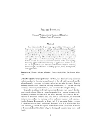
The following graph illustrates the working pressure of PVC and HDPE pipes as a function of flow velocity in theexample given above.225Working Pressure ComparsionPressure (psi)20017515012" DIPS DR18 PVC12512" DIPS DR17 HDPE100755012345678910Velocity ( ft/s )Below design velocity of 5.5 ft/s the working pressure is equal to the pressure class of HDPE (125 psi). Above thedesign velocity of 5.5 ft/s the working pressure is less than the pressure class of HDPE.The reduction in working pressure of a PVC pipe below its’ pressure class increases as the flow velocity increases. At7.5 fps the working pressure of the PVC pipe is less than that of the PE pipe.A graphical depiction of the flow rate (usgpm) and the hydraulic loss for 12” DIPS DR18 PVC and 12” DIPS DR17HDPE pipe is also presented to provide the reader a quick reference. The results are similar. In fact the plot of PEvalues is hidden by the plot of PVC results. This is not surprising since the roughness coefficient ‘C’ for both PVC andHDPE is 150 and both pipe has comparable ID and DR.Technical Service Bulletin 6
4.FATIGUE DESIGNThe number of surge cycles to fatigue failure (NCF) that a plastic pipe can tolerate, is its’ fatigue limit. To convert theNCF to a fatigue life of the pipe, the system designer / operator needs to provide an estimate of the frequency of thesurge events.Detailed literature searches conducted for Jana’s Technical Report on Fatigue of Plastic Water Pipe indicates thatthe current generation of polyethylene materials ( PE4710, PE100) are not affected by cycling loading. It is a failuremode that does not appear to occur in service. However, fatigue life calculations are possible and periodicassessment of polyethylene fatigue will confirm the exceptional fatigue resistance of this material.PVC materials are known to be susceptible to fatigue failure. The PVC pipe industry recommends that users checkthe suitability of the DR ( based on working pressure pressure rating minus surge pressure) to ensure that fatiguefailure is not an issue with the candidate DR.For additional information on fatigue life and flow velocities see the Jana’s Technical Report on Fatigue of PlasticWater Pipe c-water-pipe-01-12-12.pdf5.PPI PACEThe Plastic Pipe Institute provides a web based design tool to assist designers and owners in the evaluation of pipematerials for water distribution and transmission main systems. PPI-PACE http://ppipace.com/ allows preliminarycalculations of operating pressure, surge pressure and fatigue design life.The tool follows the design procedures in well-established and accepted water standards (ANSI/AWWA C150/151,ANSI/AWWA C900, ANSI/AWWA C901, ANSI/AWWA C905, ANSI/AWWA C906, ANSI/ASTM D2241).Design example:Pipe: 12” DIPS DR17 HDPE PE4710, 12” DIPS (CIOD) DR18 PVC and 12” DIPS PC350 DIOperating pressure: 70 psiDesign velocity for recurring surge: 5 ft/sDesign velocity for occasional surge: 8 ft/sTemperature: 57 FDesign life: 100-yearAnticipated recurring surges: 55 cycles/day or about 2 million cycles for a 100-year design lifeTechnical Service Bulletin 7
Step 1: InputFor Recurring Surge, PPI-PACE defaults to 4 fps for design velocity; the software permits entry in the 4-8 fps range.For Occasional Surge, PPI-PACE defaults to 8 fps for design velocity; the software permits entry in the 5-15 fpsrange.For Working Pressure, PPI-PACE defaults to 70 psi - which is the average working pressure in the US. The minimumallowable value in PPI-PACE is 40 psi.For Anticipated Recurring Surges, PPI-PACE defaults to 55 cycles per day per AWWA C900-07 and AWWA C905-10(Appendix B/Design Example); this results in about 1 million cycles for a 50-year design life and about 2 million cyclesfor a 100-year design life. The user should enter the appropriate number.For Temperature, PPI-PACE defaults to 57 F which is the average water temperature in the US; the software permitsentry in the range 40-100 F.Technical Service Bulletin 8
Step 2: DesignThe design fatigue life for PVC is determined using the calculation method stated in AWWA C900 and C905Appendix B using a 2:1 design factor. For PE the design fatigue life is determined using fatigue curves provided inMarshall, G.P., Brogden, S: Final report of Pipeline Innovation Contract to UKWIR, 1997 using a 2:1 design factor.The design fatigue life of Ductile Iron (DI) pipe is not shown in PPI-PACE since DI is not considerable to be fatiguelimited. The only design check is about pressure capability. The ‘right pipe’ is the one that meets design requirementsfor flow, working pressure, and fatigue life.Technical Service Bulletin 9
Step 3: ChartsPrinted report:Technical Service Bulletin 10
6.ConclusionsUI Sclairpipe Design and selection of plastic pressure pipe TB 0116, Copyright 2016 Uponor. Created in Canada.Different pipe materials define pressure class very differently. Designers should not compare pipe alternatives simplyby pressure class. The pressure class specified for PE (and PVC) should be based on the AWWA design methodsapplicable to each material, as illustrated in this Technical Bulletin.Uponor Infra Ltd.6507 Mississauga RoadT: 905-858-0206866.594.7473Mississauga, ONF: 905.858.0208Canada L5N1A6W: www.uponor.caTechnical Service Bulletin 11
Example: Working Pressure and Surge Assessment of 12" DIPS DR18 PVC pipe and 12" DIPS DR17 PE4710 HDPE pipe. Dimensional Information: 12" DIPS DR17 HDPE 12" DIPS DR18 PVC Pipe OD (in) 13.20 Pipe ID (in) 11.55 11.65 Bore Area (sq.in) 0.73 0.74 The manufacturer's published pressure class for a PVC DR18 pipe is 235 psi.