Transcription
ASHRAE1950JOURNALYE A R S59–2009The following article was published in ASHRAE Journal, March 2009. Copyright 2009American Society of Heating, Refrigerating and Air-Conditioning Engineers, Inc. It is presentedfor educational purposes only. This article may not be copied and/or distributed electronicallyor in paper form without permission of ASHRAE.Five Defrost MethodsFor Commercial RefrigerationBy Julius H. Rainwater, Member ASHRAECommercial refrigerated display and storage cabinetsnormally use one of fivedefrost methods:· Condensing unit off permittingnatural defrost;· Hot gas defrost;· Electric defrost;· Water defrost; and· Other external heat source defrost.The refrigerators described here areused in modern supermarkets to display and store perishables such as freshmeats, fresh vegetables, dairy products,Featured in ASHRAE JOURNAL, march 1959frozen foods and ice cream. The displaycases are of the open top type utilizingeither a gravity airflow or forced airflowevaporator. The usual installation ofthis refrigerator includes a multiplicityof fixtures connected to a single remotecondensing unit. In other words, themost often seen application includesseveral evaporators connected to onecondensing unit. There are many applications employing a single refrigeratorfor each condensing unit. This singlecase is either remotely connected to itsunit or is self-contained with its ownjulius h. rainwater, member ASHRAEJulius H. Rainwater was a member of the American Society ofRefrigerating Engineers (ASRE), and became a member ofASHRAE when ASRE merged with the American Society ofHeating and Air-Conditioning Engineers (ASHAE). A byproduct ofthis merger was ASHRAE Journal.When this article was written, Rainwater was director ofengineering of the Warren Company, a pioneer in commercial refrigeration. Heretired in 1975 from its successor, Kysor Warren, as vice president, engineering, andcofounded another company that is a predecessor of Hill PHOENIX Refrigeration.Rainwater, now 83, retired in the 1990s and lives in Conyers, Ga. He is finishing abook on his family’s experiences in war, starting with the American Revolution. Heis a graduate of The Georgia Institute of Technology with a degree in electrical engineering. He had a number of patents in electronic controls.38ASHRAE Journalbuilt-in unit. Storage refrigerators areof the walk-in or reach-in type. Theformer refrigerators have one or moreevaporator coils of either the gravityairflow or forced airflow type.The temperature to be maintainedin the refrigerator is one of the mostimportant factors to be consideredin the design of a defrost system. Icecream display cases must operate witha fixture temperature between –10 Fand –20 F. The refrigerant evaporatesat a temperature of approximately–40 F under these conditions. Frozenfood display refrigerators maintaina fixture temperature of 0 to –10 Fwith an evaporator temperature of–30 to –35 F. Fresh red meat refrigerators operate with a 28 to 32 F fixturetemperature and an evaporator temperature of approximately 8 F. Freshvegetable and dairy display cabinetsrequire a temperature of 36 F to 42 Fand an evaporator temperature ofapproximately 12 F.The walk-in cooler or freezer mustmaintain a product area temperaturerange approximately the same as indisplay cases; however, the evaporatingtemperatures for walk-in evaporatorsare usually about 10 degrees highera s h r a e. o rgMarch 2009
Advertisement formerly in this space.
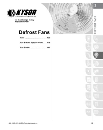
ASHRAE19than those for display cases due toa smaller temperature differentialbetween the refrigerant and productarea temperatures. In the design of anefficient defrost system another factor to be considered, which is closelyrelated to the fixture temperature, isthe means for disposing of the drainage. Where the drain is subjected totemperatures well below 32 F, somemeans must be provided to heat thedrainage system.Other factors of importance in theselection of the defrost method are theeffect on the product during the defrostperiod, sizing of the condensing unit,simplicity of the system and economyof the system. Certain products spoilif exposed to temperatures above theirnormal storage range for a prolongedperiod of time. Ice cream and frozenfoods will thaw to an unsafe pointwhen exposed to above 0 F temperatures for longer than one hour. Redmeats begin to change to a dark colorwhen exposed to temperatures above36 F for longer than an hour and ahalf. Since some discoloration takesplace during each defrost period, it isadvantageous to have as few defrostperiods in a day as possible. Milkstored for 48 hrs at 50 F has a bacteriagrowth in excess of 150 times that formilk stored at 38 F for the same periodof time, thus, frequent defrost periodsof prolonged duration are damaging to milk and other dairy products.Vegetables requiring less refrigerationthan other products can endure higherthan 38 to 42 F temperatures for longperiods.During a defrost period heat is addedto the air, product fixture walls, andevaporator metal; for this reason,40ASHRAE Journal50JOURNALYE A R S59–2009the condensing unit must be sizedto extract this heat as quickly as possible. Some defrost systems add moreheat than others in melting the samequantity of frost. Numerous defrostperiods per day require that the condensing unit extract this added heatload many times during the day. Themost efficient defrost method is thatwhich requires the least interruption ofthe equipment operation. In reality, thedefrost periods limit the capacity of theequipment as shown by the equationWhere Cd is the daily coolingdemand of the system; n is the numberof defrosts per day and t is the durationof each defrost in hours.Simplicity of the system is importantso that fewer installation and operatingproblems will arise. All factors mustbe carefully balanced to obtain an economically feasible system to give thedesired results.Condensing unit off permitting natural defrost is perhaps themost simple since little apparatus isinvolved. In this method, the condensing unit is simply permitted toremain off while the coil defrosts.Since there is no external heat added,other than that of the air surroundingthe evaporator, this system is quitelengthy in the time required to meltthe frost and as a result is limited tomedium temperature (above 28 F)range fixtures.Four ways to control this method are:manual; suction pressure control (oneach off cycle); time clock initiate andterminate; and time clock initiate andsuction pressure terminate.The manual control is simply opening the switch to the compressor motorwhen the evaporator is iced and waiting for the frost to melt before closingthe switch. A defrost period of approximately three hours is required everyother day.The second means for controllingdefrost is by adjusting the suction pressure control so that defrosting takesplace on each off cycle. This methodis limited to refrigerators which cannormally operate in the 38 to 42 Frange. It is frequently used in vegetableand dairy refrigerators where the airthrough the evaporator is circulatedby fans. A typical evaporator pressure graph is illustrated in Fig. 1. “D”represents the refrigeration cycle while“A,” “B,” and “C” represent the offcycle. “A” is the period of time duringwhich the ice, metal of evaporator andmetal of walls surrounding evaporator are rising to a temperature of 32 F.“B” is the time representing the actualmelting of the ice. “C,” time in whichthe refrigerant is rising above 32 F, is aperiod of most importance in allowingthe defrost water to drain clear of thefixture.“Off Cycle” defrosting has the advantage of allowing some cooling effectduring the defrost period since thecirculated air is flowing around meltingice. Another advantage is that the coil,free of frost most of the time, can operate near its maximum designed capacity most of the time. Even should theheat load be such that no off time canbe reached, the evaporator pressure willdrop as the coil becomes iced and willeventually drop to the pressure controlcut-out point and allow an off cycledefrost period.a s h r a e. o rgMarch 2009
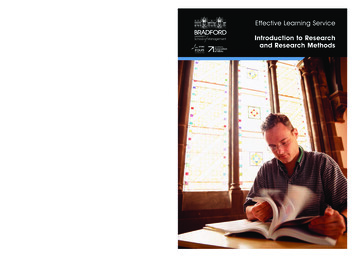
ASHRAE19f i g . 1 Evaporator pressure graph.One disadvantage is that whereremote condensing units are used, anambient at the condensing unit lowerthan the evaporator temperature cancause the suction pressure to linger at apoint below the pressure control cut-inpoint, keeping the compressor off forlong periods of time during which thefixture temperature rises to an unsafepoint. Many remote condensing unitsin the southern parts of the UnitedStates are installed outside and as aresult during the winter months theambient at the condensing unit is wellbelow the evaporator temperature. Thesolution to this problem is to use athermostat for controlling fixture temperature and a time clock for controlling the defrost.A similar disadvantage sometimesencountered is where the refrigerantlines from the fixture to the remotecondensing unit are installed intrenches or conduit with numerousother cold refrigerant suction lines,which prevent the suction pressurefrom rising to the required cut-inpoints. The use of a time clock is thesolution in this instance also.The third and fourth means for conM a rc h 2 0 0 950JOURNALYE A R S59–2009f i g . 2 Suction pressure vs. time graph for time clock defrosting.trolling the defrost period both utilizetime clocks. The time initiate and timeterminate system merely requires thatthe time clock be wired to break thecircuit to the condensing unit for apredetermined time. The duration oftime is normally 45 min to 90 min forforced air evaporators as used in vegetable, dairy, and meat fixtures. A periodof three hours or more is required forgravity airflow refrigerators.The time initiate and suction pressureterminate means of control is similarto the straight time system except thatthe switching mechanism for controlling the power to the condensing unitis reenergized by the rise in suctionpressure to a predetermined setting.This setting should be approximately46 psi (gauge) for Refrigerant-12. Thepressure terminate clock system hasthe definite advantage of allowing acomplete defrost each period regardlessof the quantity of frost existing on thecoil and regardless of the time involved.Most pressure terminate systems havea safety time limit to terminate thedefrost period by time should the pressure not rise to the pre-set point. Thissafety time limit is usually adjustable.The pressure terminate clock has thedisadvantage listed for the suction pressure “off cycle” defrosting where lowtemperature ambients are experiencedat the condensing unit or suction lines.The time clock means for controlis most frequently used with meatand dairy refrigerators. A typical suction pressure vs. time graph for timeclock defrosting is shown in Fig. 2.This graph is representative of a meatdisplay system where from two to fourdefrost periods (A, B, C) are requiredper 24 hrs. Dairy and vegetable displayrefrigerators have similar evaporatorpressure characteristics and requireapproximately the same number ofdefrost periods per day. Walk-in coolers for meats, vegetables and dairyproducts have defrost suction pressurecharacteristics similar to those shownin Fig. 2. Walk-in cooler evaporatorsusually require one or two defrost periods per day.Hot Gas Defrosting has many varieties all of which utilize a compressedvapor in the evaporator coil. Somesystems utilize the latent heat of condensation of this compressed vapor as aASHRAE Journal41
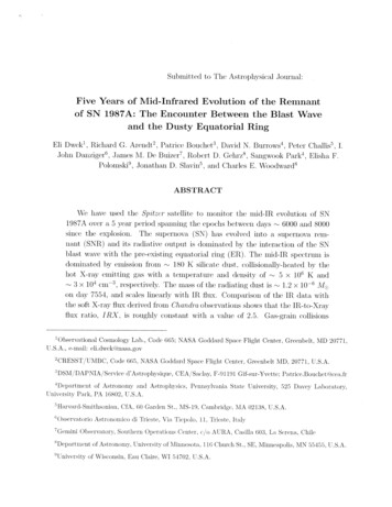
ASHRAE19f i g . 3 Hot gas defrost using a metering orifice.heat source whereas others use only thesensible heat obtained from the highlysuperheated compressed gas.Hot gas defrosting offers severaladvantages over other methods. Heatis added directly to the evaporator coils without depending uponexternal sprays or air delivery of theheat. By applying the heat internally,a rapid defrost is obtainable. The icesometimes becomes loose and fallsoff the coils before complete meltingis required. To accomplish this rapiddefrost, adequate drain heaters mustbe designed using the hot gas itselfor electric heaters. Hot gas defrostingoffers an inexpensive source of heat ascompared to methods using other heatsources.This method has several weaknessesthat have more or less been overcomeby manufacturers. The simple hot gassystem merely allows the dischargegas from the compressor to bypass thecondenser through a solenoid valve andthen flow directly into the evaporatorcoil with no metering or controllingdevices in between. This simple systemdepends upon the compressed vapor tobe condensed in the evaporator.42ASHRAE Journal50JOURNALYE A R S59–2009f i g . 4 Hot gas defrost using a vapor pot.As the defrosting progresses, thehot gas condenses in the evaporatorwith some remaining in the evaporator as a liquid while some goes backto the compressor to be recirculated asa compressed vapor with the heat ofcompression added. As time progressesmore liquid remains in the coil withless refrigerant being returned to thecompressor. Since the heat source isobtained from the circulated refrigerant, the systems gradually tend to runout of heat.Another weakness is that this systemdepends upon high ambient temperatures and high condenser pressures.When the condenser pressure is lowthe discharge gas from the compressorenters the condenser rather than theevaporator, causing an extremely lowcondensing pressure during the defrostwhich can correspond to a temperaturenear 32 F, resulting in little or no heattransfer from the refrigerant to the froston the evaporator.Danger of refrigerant liquid slugbacks to the compressor is anotherdisadvantage of this system. This liquidslug back is especially harmful just aftera defrost period.With reference to supermarket refrigerators, hot gas defrosting presentsa more complex system with addedrefrigerant lines and controls to beinstalled in the field and as a result thismethod of defrosting is used chieflyon walk-in freezer evaporators and onself-contained frozen food display cabinets. As many as six remote refrigerateddisplay cases are sometimes connectedto one compressor which prohibits aneconomical use of a hot gas system.There are several walk-in freezerevaporators available today using variations of hot gas defrosting which haveovercome most of the disadvantages asmentioned above. (Figs. 3, 4, 5 and 6.)The system shown schematically inFig. 3 uses a metering orifice where thehot gas enters into the evaporator coilas an adiabatic (isothermal) expansiontakes place. This orifice is sized to create a pressure in the evaporator lowerthan the condensing temperature ofthe refrigerant; as a result, the highlysuperheated vapor does not condensebut gives up sensible heat to the frostedevaporator coil. Since condensationdoes not take place, the problem ofliquid refrigerant slug back is over-a s h r a e. o rgMarch 2009
Advertisement formerly in this space.
ASHRAE19f i g . 5 Hot gas defrost using a heat bank.come. The orifice also serves to holdthe suction pressure below an excessiveamount.Controls for this system include atime clock which accomplishes threeperiods of time during each completedefrost period. The first interval (usually two to three min) starts the compressor and stops the evaporator fans toassure an adequate supply of hot gas.During the second period, the clockopens the hot gas line solenoid valveand energizes the electric drain panheater. This period is usually five to10 min and occurs approximately fourtimes per day. The last period is a delayperiod during which the hot gas solenoid valve opens and evaporator fansremain stopped to allow water to dripfrom the coil surface and to allow theevaporator to reach a lower temperature before resuming air circulation.This period requires a setting of threemin.Fig. 4 shows a hot gas system usinga vapor pot. This system uses an accumulator in the suction line to trap theliquid refrigerant and, by means of ableed tube, allows small amounts ofliquid refrigerant to flow back to the44ASHRAE Journal50JOURNALYE A R S59–2009f i g . 6 Hot gas defrost using a re-evaporator.compressor along with the suction gas.The bleed tube is sized to overcome theliquid refrigerant slug-back disadvantage but allows enough to pass to pickup the latent heat of vaporization incompression. This latent heat of vaporization is the source of heat utilized tomelt the evaporator frost.The accumulator or vapor pot has abuilt-in heat exchanger which is incidental and, although helpful duringthe refrigeration cycle, offers no help tothe defrost process. It is controlled by atime clock which must have a switching mechanism designed to open thehot gas solenoid valve, stop the evaporator fans and start the compressor(Fig. 3). Defrost period is terminatedeither by the timer or, as is done sometimes, by a thermostat which measuresthe temperature of the evaporator andat a pre-set point energizes a solenoidcoil in the time clock which mechanically reverses the switching mechanismto the refrigeration cycle.The heat bank method of utilizinghot gas as a defrosting means schematically depicted in Fig. 5 actually uses are-evaporator coil immersed in an insulated tank of water (heat bank). There-evaporator overcomes the refrigerantliquid slug back problem. The unusualfeature of the heat bank principle isthat a heating coil from the dischargeline of the compressor also immersedin the tank of water builds up heat andstores it during the refrigeration cycle.This heating coil also serves to prevent flood back during the refrigerationcycle by warming the suction gases inthe re-evaporator. The heating coil isprovided with a bypass which allowsthe discharge gas to go directly to thecondenser during the refrigerationcycle as the temperature rises in theheat bank. During the defrost periodthe hot gas flows to the solenoid valve,through the frosted evaporator coil,and then through the heat bank reevaporator where heat is picked upfrom the hot water. The heat bank isdesigned with a holdback valve whichmaintains a low suction pressure in there-evaporator and is set low enough toactually freeze the water. This allowsthe gas to not only pick up sensibleheat but to pick up the latent heat offusion given up by the freezing water.This method provides a continuousheat source not dependent upon thea s h r a e. o rgMarch 2009
Advertisement formerly in this space.
ASHRAE19ambient air temperatures or condensing pressures. It also serves to hold thesuction pressure below an excessiveamount.The electrical controls for the heatbank system are similar to the othersystems discussed in that a timer mustassure that the compressor is running,stop the evaporator fans, and open thehot gas solenoid valve. Normal defrosting with this system requires 3 periodsof 10 min each which includes a 3 mindrainage period.The system shown in Fig. 6 employsan unusual re-evaporator since it isan inner tube within the evaporator coiling. During defrost the hotgas solenoid valve opens to allow thecompressed vapor to flow through thisinner tube, which acts as a condenser.The heat of condensation originallyderived from the heat of compressionis the source of heat used to melt thefrost. The liquid and vapor then flowthrough the check valve and constantpressure valve which acts as an automatic expansion valve to maintain arefrigerant temperature above 32 Fand yet introduce enough pressuredrop to cause any condensed liquidto gasify before leaving the coil. Therefrigerant flowing from the constantpressure valve passes into the evaporator which serves as a re-evaporator.The actual heat used for defrosting thecoil is the heat of compression of thecompressor. This system is controlledwith a time clock as are the othersystems.Still another system is a reverse cycledefrost method whereby a four-waysolenoid valve actually reverses the flowof refrigerant during defrost to let thecondenser serve as an evaporator while46ASHRAE Journal50JOURNALYE A R S59–2009the evaporator acts as a condenserusing the meltin
Heating and Air-conditioning Engineers (ASHAE). A byproduct of this merger was ASHRAE Journal. when this article was written, Rainwater was director of engineering of the warren company, a pioneer in commercial refrigeration. He retired in 1975 from its successor, K