Transcription
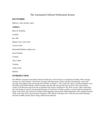
The Automated Collision Notification SystemKEYWORDShighway, crash, mayday, injuryAuthorsBruce R. DonnellyVeridianBox 400Buffalo, New York id SchabelVeridianAlan J. BlattVeridianArthur CarterNHTSAINTRODUCTIONThe NHTSA sponsored Automated Collision Notification (ACN) Project was initiated in October 1995 to design,develop, test, and evaluate a system that can detect and characterize crashes and then automatically send a datamessage to the public safety answering point (PSAP), see Figure 1. The system also opens a cellular telephone voiceline between the PSAP and the vehicle occupants after the data message has been received. The system detectscrashes in all directions and stores the acceleration time history experienced. The ACN system is able to determinethe crash change in velocity, the principal direction of crash force, whether a rollover occurred and the potential forinjury in the crash. The system also includes GPS equipment and provides PSAP dispatchers with a mapped locationof the crash. The ACN system has been installed in 700 vehicles in Western New York and real world crash dataand time of EMS response data is being collected and analyzed.
Figure 1: ACN SystemIn-Vehicle EquipmentThe components of the ACN in-vehicle equipment suite are illustrated in Figure 2. These components include: theVeridian developed In-Vehicle Module (IVM), the cellular telephone handset, the cellular telephone transceiver (3Watt), the back-up battery, and the associated antennas.Figure 2: ACN In-vehicle HardwareTransceiverThe transceiver selected for use the ACN system is the JRC 8820DR transceiver which allows automated control viaa serial control channel. Commands are available to initiate call processing, dial a number, answer an incoming call,among others. The transceiver can also provide data such as the current RSSI level, active system (A or B or noservice available), in-use, roam, etc. These controls may seem trivial, but control of a cellular phone is not asstraightforward as a land-line phone where placing a call involves merely dropping an appropriate "off-hook" loadacross the line, waiting for a dial tone, then sending DTMF tones of the appropriate length and spacing.Other than the serial control line, the only other connections to the transceiver are a reset signal and audio in/audioout.HandsetThe handset chosen is a JRC 6030 handset. This handset also allows control via a single serial control channel.Messages are sent to the IVM (the "host computer" in the handset’s view) whenever any button is pressed or
released. Further, a message is sent whenever the handset is placed in or removed from its cradle. The handset canbe directed to operate as a normal "hand-held" unit, or can be operated in a "hands-free" mode in which the audioout is directed to the larger speaker underneath the keypad, and the incoming audio taken from the microphoneabove the LCD display (two lines of 8 characters, plus icons below). The "hands-free" mode, while obviouslyintended for use when the handset is in the cradle, is totally under software control via the serial control channel;when the ACN system detects a crash, the car’s occupants are connected to the dispatcher in hands-free moderegardless of the handset’s position.BatteryThe back-up battery is a gel-cell lead-acid battery kept constantly charged by the IVM and used to provide enoughemergency power for collision reporting and an extended duration phone call or two should the car’s battery becomedisconnected or destroyed in an accident.IVMThe IVM is the key element of the ACN in-vehicle equipment suite. The IVM is packaged in a rugged aluminumhousing and contains a high performance (16 bit processor, 13.8 MIP) Digital Signal Processor (DSP), threeorthogonally mounted micro-machined accelerometers, an Analog to Digital Converter, a single chip modememploying the robust and conservative V.23 Frequency Shift Keying data transfer protocol, a Rockwell Jupiter 12channel GPS receiver board, power conditioning circuitry, and a non-volatile FLASH memory (128 Kbytes,expandable to 1024 Kbytes) to store detailed crash event time histories (see Figures 3 and 4).Figure 3: IVM - Internal View
Figure 4: IVM Board With Functional Sections HighlightedDSPThe IVM’s detection and sensor conditioning algorithms are very DSP-intensive; that is, many of the computationsare tight loops of multiply-intensive convolutional equations. The IVM uses an Analog Devices DSP, theADSP2105, to perform all the detection algorithms as well as control all the various peripheral devices andtelematics sequencing (see Figure 5).Figure 5: DSP Block DiagramThe ADSP2105 is a 16-bit fixed-point DSP with a modified Harvard architecture; i.e. it has a program data bus anda data data bus (internally) making it possible to, say, multiply an acquired data value by a stored coefficient (storedin program memory) and add it to a previous sum in a single instruction cycle.The ADSP2105 can address 16k 16-bit words of data memory, including 0.5k words which are mapped to datamemory internal to the chip, and 16k 24-bit words of program memory, including 1k words which are mapped tointernal program memory. Since the access times required for zero wait state memory accesses are short enough to
make EPROM, ROM, or FLASH memory prohibitively difficult to use, the processor is designed to use fast staticRAM for all its external memory. Upon reset, a "bootup" program is transferred from a small, relatively slow BOOTEPROM to the DSP’s internal program memory. After transfer, that program in internal program RAM (PRAM) isexecuted.The IVM has nearly a full compliment of RAM available to it; as much as the ADSP2105 can directly address, thatis. The 2105 allows for 14 k words of external program RAM, allocating 2k words for internal addressing forcompatibility with other DSP family parts. The ADSP2105 allows 14 k words of external data RAM also, mapping1k of address space for its internal registers and 1k of address space for its internal data RAM (again forcompatibility with other DSP family parts which have more internal RAM). Of the remaining 14 k words ofexternally addressable data RAM space, the IVM maps 13 k words into actual RAM, and allocates a 1 k addressblock for memory-mapped peripheral addressing. The decoding for the peripheral addresses is done withdemultiplexors and a PLD; the PLD also includes a state machine to allow slower peripherals enough setup and holdtimes for their data for, even though the DSP has a programmable wait state generator built in, these wait statessimply add time to the middle of the accesses.Since the program and data busses are multiplexed into a single data bus for external RAM access, the IVM mapsboth program RAM and data RAM into the same physical set of devices: three 32k by 8 bit RAM chips.The IVM stores many of its parameters, much of its operational code, and all of the data collected during a collisionin FLASH memory. This memory is accessed using a set of memory-mapped address registers, and a singleread/write address for data.Serial I/OA total of six serial ports are required for the IVM. Two are required for the modem since V.23 allows for anasynchronous bit rate transmission and reception (two different baud rates). One each for communication with theGPS receiver, the handset, the transceiver, and the diagnostic port.The diagnostic port is used to upload the program and parameters into the IVM, including the transformation matrixprovided by the Reference Correction Unit described below, and to upload measured event histories.Modem and Audio MultiplexingThe IVM uses a TDK 73K321 single chip modem which employs CCITT V.23 standard modulation and signaling.The call is initiated by the IVM at "normal" V.23 originate baud rates of 75 baud transmit, 1200 baud receive. Sincethe IVM will transmit the preponderance of information and reception is required only for commands andverification, after connection the channels are immediately reversed so that the IVM transmits at 1200 baud,receives at 75 baud.
Figure 6: Modem, Audio Path Block DiagramAudio path control is achieved using CMOS FET switches after proper conditioning, filtering, level shifting andamplification (see Figure 6).GPS ReceiverAs stated above, incorporated into the IVM is a Rockwell Jupiter GPS receiver. This "daughter board" is connectedto and controlled by the DSP via a serial port and discrete lines.Sensors, Conditioning, and A/DThe collision sensing is performed using three inexpensive monolithic micromachined accelerometers, two AnalogDevices’ ADXL50s and one Motorola MMAS40G, and a lot of signal conditioning in the DSP.The two ADXL50s are arranged on the board so that their (linear) axis of sensitivity is parallel to the board and atright angles to each other. The MMAS40G has an axis of sensitivity that is perpendicular to the circuit board, so thatall three of the sensors are mounted orthonormally without requiring a daughter board arrangement to achieve 3-axissensitivity.The acceleration outputs are anti-alias filtered before being converted to digital values by a 12 bit Analog to Digitalconverter.Our pass band of interest extends up to 60 Hz, and the internal processing of the actual detection algorithm andstorage of vehicle dynamics is done at 180 samples per second. However, in order to effectively and economicallyfilter to 12 bit accuracy across automotive temperatures, the accelerations are oversampled by a factor of 8 at1440 samples per second. The DSP filters to a 60 Hz cutoff and decimates the results from 1440 to 180 samples persecond. This greatly reduces the demand on the order and accuracy of the analog filters.The acceleration outputs from the ADXL50 are proportional to absolute voltage levels. However, the MMAS40G isa ratiometric device, where the measured acceleration is proportional to a percentage of the supply voltage, ratherthan an absolute voltage. Typically, the A to D converter’s reference is driven by the same supply voltage so thatany variance in the voltage is compensated. Either technique is workable, but mixing the two on a single A to D
converter creates difficulties. The IVM solves the problem by monitoring the 5V analog supply voltage andcorrecting the ratiometric sensor in software.Power Regulation and ControlPower for the IVM is derived from the automobile’s power, diode isolated and diode "ORed" with the back upbattery. After a series of protection and filtering components, the voltage is converted to 5V using a switchingregulator from the National Semiconductor Simple Switcher family.Power for the transceiver and handset is taken from the diode "ORed" node, and switched under computer controlusing a FET.The battery is float charged whenever the ignition line is on. The charging of the battery is current limited by a PTC(Positive Temperature Coefficient) thermistor.The switching regulator, and thus the power for the preponderance of the IVM, is controlled by a tiny, extremelylow power PIC microcontroller (see Figure 7). This processor is continually powered (through an independentmicropower linear voltage regulator) running from the time of installation on so long as the IVM is connected to anypower source (the main automobile power line or the back up battery). This processor serves as a power-upsequencer, a reset circuit, a wake-up timer, and a watchdog timer.Figure 7: PIC and Power Conditioning Block DiagramThe PIC will monitor the ignition sense line (reduced to TTL voltage levels) and determine if the ignition comes on.If so, the PIC will turn on the power to the rest of the IVM, and hold the DSP reset line for an appropriate duration.The DSP can also read the ignition sense line. In normal operation, when there is no collision event and the phone isnot in use, the DSP will poll the ignition line and, when it is de-asserted, will perform any "clean-up housekeeping"necessary. Then, it will inform the PIC by sending it a code that it wishes to be shut down, and woken up after a setduration. This allows the IVM to perform periodic self-test functions and report its status to a remote computer. Ifthe DSP is in the process of reporting a detected collision, even if the ignition line becomes de-asserted the unit willremain powered on until the entire event is processed.To guard against any momentary soft upsets, the PIC also acts as a watchdog timer. During normal operation, the
DSP will toggle an I/O line being read by the PIC, setting it to one polarity in the Interrupt Service Routine (ISR),and to the other in the background processing loop. If the PIC does not detect this bit toggle after a few minutes, itwill reset and re-initialize the IVM.Dispatcher Interface (Gateway)The ACN crash messages are received at the Erie County Sheriff’s Office on a PC based dispatcher interfaceconsole and a voice line is immediately opened between the Sheriff’s Office and the ACN equipped vehicle. Thedispatcher interface monitor displays a map with the crash location, the previous ten seconds of vehicle location andspeed, an icon showing the principal direction of crash force, the crash change in velocity, whether a rolloveroccurred and the vehicle final rest position (see Figure 8.). An estimate of the probability of serious injury is alsoavailable if desired. The voice line is opened as soon as the monitor display is complete and the dispatcherestablishes contact with the occupant within two minutes of the crash if the occupant is able to respond. Medicaladvice can be tele-conferenced to the crash vehicle from the Erie County Medical Center if it is needed. For ErieCounty crashes, the dispatcher alerts the appropriate responding agency and EMS, Police and Fire response isinitiated regardless of where the crash is located, whether the crash was observed by a bystander or passerby andwhether or not the occupants were conscious. For out of area crashes, the Cross Country national message center isnotified and the call is passed to the appropriate local response agency.Figure 8: Dispatcher Interface ScreenDescription of the field Operational TestACN SystemOver 700 vehicles in Western New York have been equipped with ACN systems to provide over 1000 vehicle yearsof driving exposure. Volunteer participants from the more rural areas of Erie County were recruited to have the
ACN in-vehicle equipment installed into their vehicles by Cell-One who also provided the cellular telephoneservice. In most cases the equipment was installed under the rear seat. The In-Vehicle Module (IVM) is calibrated inplace after installation, using a reference correction unit (see Figure 9), such that the triaxial accelerometer output isin the standard SAE Cartesian vehicle coordinate system regardless of the vehicle or the installation location.Several cellular telephone usage plans were offered by Cell-One to the participants; however, emergency calls andcalls to Veridian are always free of charge to the participant. After a crash occurs the crash is investigated in depth.A time line listing crash time, notification times, dispatch times and response times is constructed and analyzed toidentify the effect of the ACN time on response time.Figure 9. Reference correction unit.Crash Event TimerIn addition to the ACN system, 3000 crash event timers (CETs) have been installed in vehicles in Western NewYork to collect the baseline notification and response times for crashes when ACN systems are not involved. Thefield operational test will include 4000 CET vehicle years in the field. These data provide the control times requiredto measure the improvement in notification and response time obtained with the ACN system. The CET consists of asmall timer unit(see Figure 10) that is attached to the firewall of the vehicle and a small inertia sensor thatrecognizes a crash and starts the timer. The timer runs for three weeks before it automatically resets itself. Afterbeing notified of the crash by the vehicle owner, Veridian investigators go to the crash vehicle and read the timer toobtain the elapsed time since the crash. The actual crash time is calculated from the time of the reading and theelapsed time. The EMS, Police and Fire records then are analyzed to yield the baseline notification and responsetimes for non-ACN crashes.Status of TestAt the present time the program is approximately 60% complete in terms of days-in-the-field with 639 ACNequipped vehicles in the field and 2930 CET equipped vehicles in the field. To date nineteen CET crashes have beenexperienced of which six are rural and nine ACN crashes have been experienced of which three are rural. Theoperational field test will be complete in September 1999.
Figure 10. Crash Event TimerResultsTo date thirty-six ACN crashes have occurred of which ten were above the crash threshold. These ten abovethreshold crashes are summarized in Table 1. In eight out of the ten cases the ACN system provided an emergencynotification message to the Sheriff’s office in less than two minutes. In the other two cases a message was not sentbecause (1)the in-vehicle equipment was not operational at the time of the crash due to incorrect wiring duringinstallation and (2) the crash occurred in Chicago, Illinois and although the system did detect the crash and assemblea message it did not make a long distance telephone call to New York.Crash #ACN I.D. #Incident orCrash?CrashDateCrash njuries & Max.AISMedical1440-1129Crash1/3/98Chicago, ILUrban8Neck strain andcontusions(AIS-1)2 of 8 octransporambulan2440-1104Crash2/18/98Buffalo, NYUrban2Sternum fracture(AIS-2)Both dritransporambulan3440-1239Crash4/4/98Marilla, NYSuburban1Right ast Aurora, NYRural1No injuryNone5440-1109Crash5/8/98Buffalo, NYUrban5Right legcontusions(AIS-1)4 of 5 octransporambulan6440-1254Crash8/31/98Hamburg, NYSuburban3No injuryNone
7440-1463Crash11/15/98Rochester, NYUrban5Driver - seat beltrelatedcontusions(AIS 1)None8440-1094Crash1/31/99Cheektowaga, NYSuburban3RF Passenger Fxvertebra - L1(AIS 2)Ambula9440-1346Crash3/3/99East Aurora, NYSuburban210440-1343Crash3/4/99Newstead, NYRural1AmbulaNo injuryTable 1: Summary of ACN Above-threshold CrashesACN Crash 440-1109Crash I.D. #440-1109 involved an ACN equipped 1993 Plymouth Voyager mini-van that was struck from the rearwhile waiting at a red traffic signal. The mini-van was pushed forward and into the rear end of the vehicle waiting infront of it. The result was two collisions, a rear and a frontal, both of which exceeded the crash thresholds of theIVM. Figure 11 summarizes the crash, shows photographs of the mini-van and shows the triaxial accelerometer datarecorded by the IVM and stored in flash memory. Both events are clearly seen in the acceleration time history as apositive x acceleration excursion (the rear crash) followed by a quiescent period and a negative x accelerationexcursion (the frontal crash). The IVM calculates the crash delta velocity and the principal direction of force(PDOF) for each crash event, indicates whether a rollover occurred and determines the final rest position of thevehicle after the crash is over (see Figure 11). Figure 12 is a crash scene diagram showing the events of the crash asreconstructed by a crash investigator. The IVM obtains the same information as post-crash reconstruction and makesit immediately available to EMS, Police and Fire dispatchers to be used in the dispatch process.None
Figure 11. Crash summary for ACN Crash No. 440-1109.Figure 12. Crash scene diagram for ACN Crash No. 440-1109.ACN Crash 440-1094Crash I.D. #440-1094 involved an ACN equipped 1991 Ford Explorer sport utility vehicle that was struck in the leftside by a vehicle making a left turn across the Explorer’s lane. The Explorer went into a counterclockwise skid andsubsequently struck a frozen snow bank on
The IVM is the key element of the ACN in-vehicle equipment suite. The IVM is packaged in a rugged aluminum housing and contains a high performance (16 bit processor, 13.8 MIP) Digital Signal Processor (DSP), three orthogonally mounted micro-machined accelerometers, an Analog to Digital Converter, a single chip modem