Transcription
ANL-ART-165Draft ASME Section III Division 5 Code Cases toextend EPP strain limits and creep-fatigue designmethods to Grade 91Applied Materials Division
About Argonne National LaboratoryArgonne is a U.S. Department of Energy laboratory managed by UChicagoArgonne, LLC under contract DE-AC02-06CH11357. The Laboratory’s main facilityis outside Chicago, at 9700 South Cass Avenue, Argonne, Illinois 60439. Forinformation about Argonneand its pioneering science and technology programs, see www.anl.gov.DOCUMENT AVAILABILITYOnline Access: U.S. Department of Energy (DOE) reports produced after 1991and a growing number of pre-1991 documents are available free at OSTI.GOV(http://www.osti.gov/), a service of the US Dept. of Energy’s Office of Scientificand Technical Information.Reports not in digital format may be purchased by the publicfrom the National Technical Information Service (NTIS):U.S. Department of CommerceNational Technical InformationService 5301 Shawnee RdAlexandria, VA 22312www.ntis.govPhone: (800) 553-NTIS (6847) or (703) 605-6000Fax: (703) 605-6900Email: orders@ntis.govReports not in digital format are available to DOE and DOE contractorsfrom the Office of Scientific and Technical Information (OSTI):U.S. Department of EnergyOffice of Scientific and Technical InformationP.O. Box 62Oak Ridge, TN 37831-0062www.osti.govPhone: (865) 576-8401Fax: (865) 576-5728Email: reports@osti.govDisclaimerThis report was prepared as an account of work sponsored by an agency of the United States Government. Neither the UnitedStates Government nor any agency thereof, nor UChicago Argonne, LLC, nor any of their employees or officers, makes anywarranty, express or implied, or assumes any legal liability or responsibility for the accuracy, completeness, or usefulness of anyinformation, apparatus, product, or process disclosed, or represents that its use would not infringe privately owned rights.Reference herein to any specific commercial product, process, or service by trade name, trademark, manufacturer, or otherwise,does not necessarily constitute or imply its endorsement, recommendation, or favoring by the United States Government or anyagency thereof. The views and opinions of document authors expressed herein do not necessarily state or reflect those of theUnited States Government or any agency thereof, Argonne National Laboratory, or UChicago Argonne, LLC.
ANL-ART-165Draft ASME Section III Division 5 Code Cases to extend EPPstrain limits and creep-fatigue design methods to Grade 91prepared byM. C. Messner and T.-L. ShamApplied Materials Division, Argonne National LaboratoryAugust 2019
AbstractThis report describes the drafting of Code Cases extending the ASME Boiler and Pressure VesselCode Section III, Division 5, Subsection HB, Subpart B design by elastic perfect-plastic (EPP)analysis methods to Grade 91 steel. The primary technical challenge is that Grade 91 steel is acyclic softening material and so modifications to the current ASME design approach foraustenitic stainless steel were required to produce conservative designs. Previous workestablished the technical basis required to support these modifications. This report provides thefull package for balloting by ASME – both revised Code Case language and associatedbackground documentation for two nuclear code cases: N-861 covering ratcheting strain limitsand N-862 covering creep-fatigue damage. The completion of this work and successful ballotingat ASME, currently underway, allows designers to apply the efficient EPP methods to Grade 91high temperature structural components.
Table of ContentsAbstract . iiiTable of Contents .vList of Figures . viiList of Tables . ix1. Introduction .112. N-861: Ratcheting .133. N-862: Creep-fatigue .334. Conclusions .44Acknowledgements .45References .47
List of FiguresFigure 2.1. Strain limits Pass/Fail criteria illustrated. 17Figure 2.2. Weld region model boundaries. 18Figure 2.3. Test geometry and load cycle history used to assess the EPP strain limits method(Messner, 2018). . 23Figure 2.4 The strain limits design life for the inelastic simulations, the unmodified EPP method,and the modified EPP method using softened isochronous stress-strain curves and yield strengths(Messner, 2018). . 24Figure 2.5 Simulated softened isochronous stress-strain curves at 550 C after 1,000 pre-fatiguecycles with a strain range of 0.4%. The solid curves are simulated isochronous stress-straincurves with no precycling, i.e. simulated versions of the standard Section III, Division 5 HBBisochronous stress-strain curves. The dashed lines are corresponding softened isochronousstress-strain curves. From top to bottom the colors represent the hot tensile curve and thenisochronous curves for 10, 100, 1,000, 10,000, 100,000, and 500,000 hours life (Messner, 2018). 25Figure 2.6. Results of a strain-controlled cycle (fatigue) test on a sample of Grade 91, conductedat Argonne National Laboratory. (Messner, 2018). . 26Figure 2.7. Cyclic data used to establish experimental yield stress softening factors (Messner,2018). Experimental data in solid lines, extrapolations in dashed lines. . 27Figure 2.8. ORNL experimental data for the combined fatigue-creep test, compared to areference creep curve for Grade 91 from Kimura, 2009 (Messner 2017). . 30Figure 2.9. Softening factors as a function of cycle count for 625 as calculated from the ORNLexperimental data. . 31Figure 2.10. Softening factors as a function of cycle count for 650 as calculated from theORNL experimental data. . 31Figure 3.1. Weld region model boundaries. 37Figure 3.2. Example problem used to assess the effect of cyclic softening on the EPP creepfatigue method (Messner, 2018). . 42Figure 3.3. Results of the comparison: the unmodified EPP method is always conservative, evenwith a substantial number of pre-fatigue cycles (Messner, 2018). . 43
List of TablesTable 2.1 Softening Factor 𝐹𝐹𝐹𝐹 . 15Table 2.2 Softening Factor 𝐹𝐹𝐹𝐹𝐹𝐹𝐹𝐹𝐹𝐹 . 15Table 2.3. Experimental yield strength softening factors. . 28Table 2.4 Model isochronous stress-strain curve softening factors. . 29
Draft ASME Section III Division 5 Code Cases to extend EPP strain limits and creep-fatigue designmethods to Grade 91August 20191.IntroductionThis report describes the extension of the ASME elastic perfectly plastic (EPP) design methodsto components designed and fabricated from Grade 91 steel (9Cr-1Mo-V). This report consistsof the balloting packages provided to ASME to support the formal modification of the existingEPP Nuclear Codes Cases N-861 and N-862, currently only applicable to 304 and 316 stainlesssteel. Chapter 2 and Chapter 3 contain these balloting packages. Chapter 2 applies to Code CaseN-861, which applies the EPP design method to the ASME Section III, Division 5, SubsectionHB, Subpart B ratcheting strain limits. Chapter 3 applies to Code Case N-862 on creep-fatiguecriteria. Both chapters follow the same outline: the first section of the chapter provides theactual Code Case language and the second subsection provides the background documentprovided to the relevant ASME Code Committees along with the Code Case. Chapter 4summarizes the current status of the revised, Grade 91 Code Cases in the ASME CodeCommittee structure at the time this report was finalized.The current ASME EPP approach for stainless steel represents a better balance of analysiscomplexity, rule complexity, and accuracy in life prediction when compared to the baselineSection III, Division 5, Subsection HB, Subpart B design by elastic analysis and design byinelastic analysis methods. The goal for the EPP methods is to provide designers a way torapidly evaluate prospective designs with sufficient accuracy to make informed design decisions.The implementation and adoption of this new design method therefore has the potential to reducedesign costs and increase the spectrum of designs that can be economically evaluated, leading tohigh temperature reactor components with reduced overall cost and improved safetyperformance.The technical background for extending the existing EPP design methods to Grade 91 wasdeveloped in past years with support from the Advanced Reactor Technologies (ART) Programand is summarized in two Argonne National Laboratory (ANL) technical reports: Messner, M. C. and Sham, T.-L. “Initial development and extension of EPP methods toGrade 91.” Argonne National Laboratory technical report ANL-ART-133, 2018.Messner, M. C. and Sham, T.-L. “FY17 Status Report on the Initial EPP Finite ElementAnalysis of Grade 91 Steel.” Argonne National Laboratory technical report ANL-ART94, 2017.The ASME background documents summarize this technical basis for Code Committee use. Thefigures used in the background documents reproduced here are mostly drawn from these twoprevious reports.The exception is new work on the softening factors used in the EPP ratcheting strain limitsprocedure for Grade 91 at temperatures greater than 600 C. A new process for setting thesefactors was developed this fiscal year after feedback from some of the ASME Code Committeemembers. This new softening factors, the new process, and the tests run at Oak Ridge NationalLaboratory supporting the new factors, are described in Chapter 2.The current ASME EPP methods for stainless steel tacitly assume a cyclic hardening materialresponse. This allows the methods to bound the accumulated deformation (for N-861) andaccumulated creep-fatigue damage (for N-862) in a component using a simplified EPP analysisANL-ART-16511
Draft ASME Section III Division 5 Code Cases to extend EPP strain limits and creep-fatigue designmethods to Grade 91August 2019with a pseudo-yield stress, which may not equal the actual material yield stress. The EPPanalysis is a tool for generating a bounding analysis result, rather than an accurate representationof the material’s constitutive response. Because the austenitic steels are hardening materials theprevious version of the method bases these pseudo-yield stresses on material test data collectedfrom virgin material that has not been pre-cycled. For N-861 this material test data is the yieldstress and the values of the isochronous stress-strain curve, which summarize time-dependentdeformation in the material. For N-862 this test data are creep rupture stress values. As thestainless steels work and cycle harden, cyclic deformation would only increase these materialproperties, meaning using the values collected from uncycled material is conservative.Grade 91 is however a cyclic softening material which means cyclic deformation will degradethe material properties required in the EPP design calculations. Calculations and experimentssummarized in Chapter 3 demonstrate that the ASME method of handling creep-fatigueinteraction, the creep-fatigue damage or D-diagram, already accounts for the effect of cyclicsoftening in Code Case N-862 and so minimal modifications are required to extend this CodeCase. However, in Code Case N-861 softening factors on the material yield stress andisochronous stress-strain curves are required to account for the effect of cyclic softening. Thisreport summarizes the past work on establishing the conservative softening factors now includedin the modified draft Code Case. Additional work this fiscal year developed an alternativemethod for establishing softening factors at very high temperatures, which was used to determinethe final factors sent to ASME for ballot.The Code Case language and background documents presented here form the basis of thepackage currently being balloted at ASME. The final chapter of this report summarizes theballoting progress and discusses the path towards final AMSE approval for the revised CodeCases.12ANL-ART-165
Draft ASME Section III Division 5 Code Cases to extend EPP strain limits and creep-fatigue designmethods to Grade 91August 20192.N-861: Ratcheting2.1.Draft Code Case LanguageCase N-861-1Satisfaction of Strain limits for Division 5 Class A Components at Elevated TemperatureService Using Elastic-Perfectly Plastic Analysis.Section III, Division 5Inquiry: What alternative rules may be used for the evaluation of strain limits for Type 304 SS,Type 316 SS, and 9Cr-1Mo-V steel in compliance with Section III, Division 5, Subsection HB,Subpart B, HBB-3252 and Nonmandatory Appendix HBB-T?Response: Strain limits for 304 SS, 316 SS, and 9Cr-1Mo-V steel per Section III, Division 5,Table HBB-I-14.1(a) may be evaluated using elastic-perfectly plastic material models instead ofthe procedures of Section III, Division 5, HBB-T-1320, HBB-T-1330, and HBB-T-1713 whenperformed in accordance with the requirements of this Code Case.1 General Requirements.Except as identified herein, all requirements of Section III, Division 5, Subsection HB, Subpart Bapply to components designed in accordance with this Code Case.The design methodology employed for evaluation of strain limits is based on rapid cycleratcheting analyses using a small strain theory elastic-perfectly plastic material model where theyield stress is adjusted based on a pseudo yield stress selected to bound accumulated inelasticstrain. Guidance on ratcheting analysis is provided in Appendix I. In this code case the term“pseudo yield stress” refers to a temperature dependent isochronous stress based on the total timeduration of high temperature service and a target inelastic strain multiplied by a softening factor,not to exceed the yield strength of the material at temperature multiplied by a softening factor.The pseudo yield stress is explicitly defined in Section 4, Step 2 of this Code Case.(a) This design methodology is not applicable to skeletal structures, e.g. a bar with uniform axialload throughout, nor structures were geometrical nonlinearities exist, e.g. canopy or omegaseals.(b) The stamping and data reports shall indicate this Case number and applicable revision.2 Load Definition.Define all applicable loads and load cases per Section III, Division 5, HBB-3113.2, ServiceLoadings.2.1 Composite cycle definitionFor the purpose of performing an elastic-perfectly plastic ratcheting analysis an overall cyclemust be defined which includes all relevant features from the individual Level A, B and CService Loadings identified in the Design Specification. Relevant features include, as aminimum, the time dependent sequence of thermal, mechanical and pressure loading includingANL-ART-16513
Draft ASME Section III Division 5 Code Cases to extend EPP strain limits and creep-fatigue designmethods to Grade 91August 2019starting and ending conditions. Such an overall cycle is defined herein as a composite cyclesubject to the following requirements.(a) An individual cycle as defined in the Design Specifications cannot be further subdivided intoindividual cycles to satisfy these requirements.(b) Except as described in (c), a single cycle from each Level A, B and C Service Loading cycletype shall be included in the composite cycle for evaluation of strain limits.(c) Level C Service Loadings may be combined with the applicable Level A and B ServiceLoadings to define an additional composite cycle(s) to be evaluated separately from thecomposite cycle defined in(d) Multiple composite cycles that include Level C Service Loadings may be defined for separateevaluation. The total number of Level C Service Loading cycles shall not exceed 25.3 Numerical Model.Develop a numerical model of the component including all relevant geometry characteristics.The model used for the analysis shall be selected to accurately represent the componentgeometry, boundary conditions, and applied loads. The model must also be accurate for smalldetails, such as small holes, fillets, corner radii, and other stress risers. The local temperaturehistory shall be determined from a thermal transient analysis based on the thermal boundaryconditions determined from the loading conditions defined in Section 2.4 Requirements for Satisfaction of Strain Limits.Perform a ratcheting analysis for each of the composite cyclic histories defined in Subsection2.1. Each of these cyclic histories must be shown to be free from ratcheting based on the pseudoyield stress S xT as defined in Step 2. In the following steps, inelastic strain for a particular stress,time and temperature is obtained by subtracting the elastic strain from the total strain as given bythe isochronous stress strain curve at the same stress, time and temperature. Additionalrequirements for weldments are shown in Section 5.Step 1: Define tdesign as the total time duration of high temperature service for all Level A, B, andC Service Loadings when the temperature is above the range covered by Tables 2A, 2B, and 4 ofSection II, Part D.Step 2: Select a target inelastic strain, x , where 0 x ε avg and ε avg is equal to 0.01 for basemetal or 0.005 for weldments. Define a pseudo yield stress S xT at each location, using thetemperature determined from the transient thermal analysis. This pseudo yield stress is equal tothe lesser of the quantities defined below in 4.2.1. and 4.2.2.(a) The yield strength S y given in Section III, Division 5, Table HBB-I-14.5 multiplied by thesoftening factor 𝐹𝐹𝑦𝑦 given in Table 2.1. Values in Table 2.1 may be linearly interpolated betweenthe listed temperatures.(b) The stress to cause x inelastic strain in time tdesign , as determined from the isochronous stressstrain curves in Section III, Division 5, Figure HBB-T-1800 multiplied by the temperature-14ANL-ART-165
Draft ASME Section III Division 5 Code Cases to extend EPP strain limits and creep-fatigue designmethods to Grade 91August 2019dependent softening factor 𝐹𝐹𝐼𝐼𝐼𝐼𝐼𝐼𝐼𝐼 in Table 2. Values in Table 2.2 may be linearly interpolatedbetween the listed temperatures.Temperature, F ( C)304 SS700 (371)Table 2.1 Softening Factor 𝐹𝐹𝑦𝑦316 SS9Cr-1Mo-V1.01.00.88800 (427)1.01.00.85900 (482)1.01.00.841000 (538)1.01.00.811100 (593)1.01.00.761200 (649)1.01.00.631300 (704)1.01.0n/a1400 (760)1.01.0n/a1500 (816)1.01.0n/aTable 2.2 Softening Factor e, F ( C)304 SS316 SS9Cr-1Mo-V700 (371)1.01.00.87800 (427)1.01.00.83900 (482)1.01.00.811000 (538)1.01.00.761100 (593)1.01.00.721200 (649)1.01.00.301300 (704)1.01.0n/a1400 (760)1.01.0n/a1500 (816)1.01.0n/aANL-ART-16515
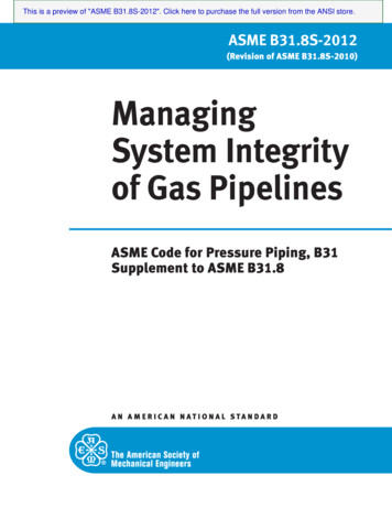
Draft ASME Section III Division 5 Code Cases to extend EPP strain limits and creep-fatigue designmethods to Grade 91August 2019Step 3: Perform a cyclic elastic-perfectly plastic analysis for each composite cycle defined inparagraph 2.1(b) above with temperature-dependent pseudo yield stress S xT . If ratcheting doesnot occur, obtain the plastic strain distribution throughout the component. The plastic strain, ε p , isevaluated according toε p23( ) (ε ) (ε ) εp x2py2pz2( ) 2 ε xyp2( ) 2 ε yzp2( ) 2 ε zxp2where the plastic strain components, ε xp , ε yp , ε zp , ε xyp , ε yzp and ε zxp , are those accumulated at theend of the composite cycle.Step 4. Assess acceptability in accordance with (a) and (b) below by using the plastic strains, ε p ,from Step 3. If the requirements of both (a) and (b) are satisfied, then the strain limits of SectionIII, Division 5, HBB-T-1310 for base metal and HBB-T-1713 for weldments are also consideredsatisfied. This condition is illustrated in Figure 2.1(a).(a) The requirement, x ε p ε avg , must be satisfied at least at one point for all through-thicknesslocations. As defined in Step 2, ε avg is equal to 0.01 for base metal or 0.005 for weldments.Failure of this requirement is illustrated in Figure 2.1(b).(b) The requirement, x ε p ε local , must be satisfied at all points. The local strain limit, ε local , isequal to 0.05 for base metal and 0.025 for weldments. Failure of this requirement is illustrated inFigure 2.1(c).(c) In order to proceed if either of the requirements of (b) or (c) are not satisfied, return to Step 2and select a smaller value of the target inelastic strain, x. If it is not possible to find a value of xthat does not ratchet and also satisfies the requirements of Step 4, then the loading conditions ofSection 2 applied to the component configuration defined in Section 3 do not met therequirements of this code case.16ANL-ART-165
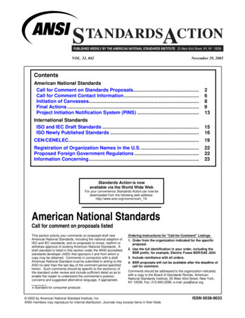
Draft ASME Section III Division 5 Code Cases to extend EPP strain limits and creep-fatigue designmethods to Grade 91August 2019PassFailFail(a)(c)(b)x ε p ε aveε ave x ε p ε localx ε p ε localFigure 2.1. Strain limits Pass/Fail criteria illustrated5 Weldments.Implementation of the strain limits for weldments defined above in Section 4 requires additionalconsideration.5.1 Weld region model boundaries.The weld shown in Figure 2.2 represents a general full-penetration butt weld in a shell. Otherweld configurations are needed for construction of an elevated temperature component inaccordance Section III, Division 5, Subsection HB, Subpart B. Section III, Division 5, HBB4200 refers to various Section III, Division 1 Article NB-4000 paragraphs for weldconfigurations and requirements. These Subsection NB weld configurations are represented bythe shaded region.Figure 2 shows a full-penetration butt weld as an example. As shown, w1 and w2 , as needed todefine the weld region for use of this Case, are approximations consistent with the specified weldconfiguration and parameters. The specified weld region must include applicable stressconcentrations in accordance with the requirements for analysis of geometry of Section III,Division 5, HBB-T-1714.ANL-ART-16517
Draft ASME Section III Division 5 Code Cases to extend EPP strain limits and creep-fatigue designmethods to Grade 91August 2019Flush groundEffective modelingedges of the weldStress concentrationif applicable per HBB-T-1714Figure 2.2. Weld region model boundaries5.2 RequirementsThe requirements for analysis of geometry of Section III, Division 5, HBB-T-1714 are applicablefor satisfaction of the requirements of this Code Case.5.3 PropertiesThe thermal/physical properties of weldments may be assumed to be the same as thecorresponding base metal for the base metal - weld combinations listed in Section III, Division 5,Table HBB-I-14.105.4. Dissimilar metal welds.This Code Case may not be used to evaluate strain limits in dissimilar metal welds.Appendix IShakedown AnalysisPerform a ratcheting analysis to demonstrate compliance with strain limits as follows:(i) Define Composite Cycle Load Time-Histories and Step(s)(a) Composite cycle load may consist of histories of mechanical loads, pressure loads,displacements, temperatures and thermal boundary conditions.(b) Time-independent parts of the cycle may be truncated because elastic-perfectly plasticanalysis is not time dependent.(c) The cycle should not have discontinuities. Discontinuities arising from the selection ofthe specified cycles to form a composite cycle should be eliminated by a simple andreasonable transition from one state to the next.(d) Subject to the requirements in (b), the composite cycle time does not affect the result ofthe shakedown analysis.(e) Temperatures, thermal boundary conditions, boundary displacements and mechanicalloads over a cycle should be cyclic; that is, begin and end at the same value.18ANL-ART-165
Draft ASME Section III Division 5 Code Cases to extend EPP strain limits and creep-fatigue designmethods to Grade 91August 2019(f) A single analysis step may represent one cycle. Dividing a single cycle into more thanone step to facilitate definition of the load cycle, and to ensure that maximum loads areanalyzed, is often helpful.(ii) Define Analysis Types.(a) A sequentially coupled thermal-mechanical analysis of the composite cycle may beperformed. First a thermal analysis is performed to generate temperature histories. Nextthe mechanical analyses are performed using these temperature histories as inputs. Caremust be taken that times in the mechanical analysis step and in the previous thermalanalysis are the same or do not conflict, depending on the requirements of the analysissoftware.(b) Alternatively, a coupled thermal-mechanical analysis may be performed. The compositetemperature history to be used in the mechanical analysis should be cyclic, that is thebeginning and end temperature distributions should be the same.(iii)Define Material Properties.(a) For thermal analyses, density, temperature- dependent specific heat and conductivity willgenerally be required.(b) For the mechanical analyses the temperature-dependent properties required are modulus,Poisson’s ratio and mean expansion coefficient. Density may also be required.(iv) Perform Analyses.(a) Perform an elastic-plastic cyclic mechanical and thermal stress analysis using thetemperature-dependent yield property defined above. Enough cycles are required todemonstrate shakedown or otherwise.(b) Care must be taken to ensure that the analysis deals with all the changes within a cycle.Elastic-plastic routines increase increment size where possible, and may miss a detail inthe loading. A conservative limit to maximum increment size can address this problem,or division of the cycle into more than one step as in (a)(6) of this Appendix.(c) Numerical shakedown analysis using finite element analysis are extremely sensitive tothe numerical parameters controlling the solution accuracy. Shakedown analysis shouldrequire the analysis method to report as accurate solutions as possible by decreasingsolver tolerances and otherwise altering the solver parameters.(v) Ratcheting.(a) Ratcheting is defined as non-cyclic strain accumulation.components differ from cycle to cycle.That is, the total strain(b) Shakedown is defined as the opposite of ratcheting – a model shakes down if the strainsat all points become periodic with increasing numbers of load cycles.(c) Failure to shakedown may be identified by plotting histories of strain at critical locationsin the model.ANL-ART-16519
Draft ASME Section III Division 5 Code Cases to extend EPP strain limits and creep-fatigue designmethods to Grade 91August 2019(d) Because of accumulated numerical error finite element analysis results will nevershakedown exactly. Plastic shakedown, defined as shakedown behavior where the steadycycle contains some plastic deformation, is acceptable for this Code Case. Models thatshake down plastically will have appreciable integration errors, manifested as slight nonperiodicity in the cycle strains. The analyst must distinguish this “false ratcheting” fromactual ratcheting in making the shakedown/ratcheting determination.2.2.Background documentOverviewThe goal of this Code Case revision is to extend a previously developed method for usingsimplified, elastic-perfectly plastic analysis (EPP) for evaluating structures against the SectionIII, Division 5, Subsection HB, Subpart B (HBB) strain limits design criteria to 9Cr-1Mo-Vsteel. The method has been previously established and codified for 304 and 316 stainless steelsthrough Code Case N-861. This background document does not reiterate the detailed derivationof the method nor the validation experiments and numerical studies used to demonstrate itsconservatism. For this basic background method refer to the following bibliography: Background documents for Code Case N-861 (RC14-1445).Carter, P. “Analysis of cyclic creep and rupture. Part 1: bounding theorems and cyclicreference stresses.” International Journal of Pressure Vessels and Piping, 82(1): pp. 1526, 2005.Carter, P.
criteria. Both chapters follow the same outline: the first section of the chapter provides the actual Code Case language and the second subsection provides the background document provided to the relevant ASME Code Committees along with the Code Case. Chapter 4 summarizes the current status of the revised, Grade 91 Code Cases in the ASME Code