Transcription
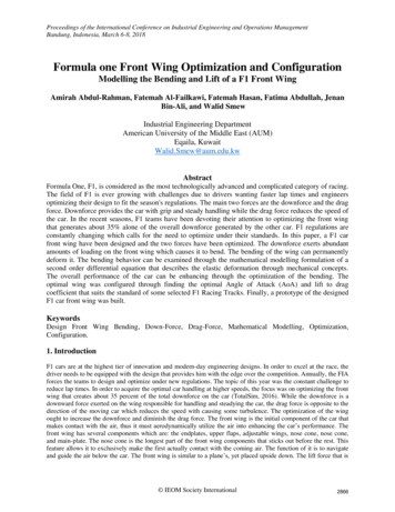
Proceedings of the International Conference on Industrial Engineering and Operations ManagementBandung, Indonesia, March 6-8, 2018Formula one Front Wing Optimization and ConfigurationModelling the Bending and Lift of a F1 Front WingAmirah Abdul-Rahman, Fatemah Al-Failkawi, Fatemah Hasan, Fatima Abdullah, JenanBin-Ali, and Walid SmewIndustrial Engineering DepartmentAmerican University of the Middle East (AUM)Eqaila, KuwaitWalid.Smew@aum.edu.kwAbstractFormula One, F1, is considered as the most technologically advanced and complicated category of racing.The field of F1 is ever growing with challenges due to drivers wanting faster lap times and engineersoptimizing their design to fit the season's regulations. The main two forces are the downforce and the dragforce. Downforce provides the car with grip and steady handling while the drag force reduces the speed ofthe car. In the recent seasons, F1 teams have been devoting their attention to optimizing the front wingthat generates about 35% alone of the overall downforce generated by the other car. F1 regulations areconstantly changing which calls for the need to optimize under their standards. In this paper, a F1 carfront wing have been designed and the two forces have been optimized. The downforce exerts abundantamounts of loading on the front wing which causes it to bend. The bending of the wing can permanentlydeform it. The bending behavior can be examined through the mathematical modelling formulation of asecond order differential equation that describes the elastic deformation through mechanical concepts.The overall performance of the car can be enhancing through the optimization of the bending. Theoptimal wing was configured through finding the optimal Angle of Attack (AoA) and lift to dragcoefficient that suits the standard of some selected F1 Racing Tracks. Finally, a prototype of the designedF1 car front wing was built.KeywordsDesign Front Wing Bending, Down-Force, Drag-Force, Mathematical Modelling, Optimization,Configuration.1. IntroductionF1 cars are at the highest tier of innovation and modern-day engineering designs. In order to excel at the race, thedriver needs to be equipped with the design that provides him with the edge over the competition. Annually, the FIAforces the teams to design and optimize under new regulations. The topic of this year was the constant challenge toreduce lap times. In order to acquire the optimal car handling at higher speeds, the focus was on optimizing the frontwing that creates about 35 percent of the total downforce on the car (TotalSim, 2016). While the downforce is adownward force exerted on the wing responsible for handling and steadying the car, the drag force is opposite to thedirection of the moving car which reduces the speed with causing some turbulence. The optimization of the wingought to increase the downforce and diminish the drag force. The front wing is the initial component of the car thatmakes contact with the air, thus it must aerodynamically utilize the air into enhancing the car’s performance. Thefront wing has several components which are: the endplates, upper flaps, adjustable wings, nose cone, nose cone,and main-plate. The nose cone is the longest part of the front wing components that sticks out before the rest. Thisfeature allows it to exclusively make the first actually contact with the coming air. The function of it is to navigateand guide the air below the car. The front wing is similar to a plane’s, yet placed upside down. The lift force that is IEOM Society International2866
Proceedings of the International Conference on Industrial Engineering and Operations ManagementBandung, Indonesia, March 6-8, 2018responsible of pushing the airplane upwards with an upward direction is the same negative lift force which is alsocalled a downforce that instead forces the car to stay grounded with a downward direction due to how that wing isplaced. The airflow that was forced to head downward by the nose cone will head over to the main plane. The mainplane will split this flow into two, one going over it and one going under it. The air over the plate will inflict adownward pressure on the plate. As this flow continuous, the shape of the wing will resist this airflow causing it tobe denser and correspondingly heavier. The air will be slower and more condense at the resistance causing themolecules to be closer to one another which causes more pressure on the main-plate. The force resulting from thiswill have a downwards direction. As for the air beneath the wing, it will move a lot faster due to the shape of thewing. The pressure will be lower due to the high speed and density of the molecules. The force will be in anupwards direction. The resulting force between the two pressures will ultimately be downwards due to the airflowand pressure at the top being a lot greater. As for the air that flows on the sides of the car, the endplates will directthem around the tires since otherwise the contact between the approaching airflow and tires will cause turbulence.The tires are engineered to be aerodynamic therefore they will not benefit from the airflow. Upper flaps also sharethe function of redirecting the air over the tires upwards to decrease instabilities. As for the adjustable wings, theycan be adjusted in order to have different angles. The higher the angle the more pressure and downforce will be onthe main-plane and vice versa.Figure 1: F1 Car’s Front WingFigure 2: Downforce Location1.1 Problem StatementThe manipulation of influential existing variables acts as a function that will allow the study of the bending'sbehavior under different circumstances. A solution and proper parameter values must be found in order to optimizethe bending. The function would aid greatly due to the changing regulations and demanding nature of F1 racing1.2 Objective1.2.3.4.Optimize the bending of the front wingFind the corresponding angle of attack and lift to drag ratiosProvide wing configurations for several tracksBuild a SolidWorks model1.3 Weather conditionsWeather conditions (e.g., density, pressure, and temperature) effects on the performance of the F1 car.Temperature and density are inversely proportional. The lower the temperature is the more density the air isgoing to have. Cold air is much heavier than hot air due to its molecules being closer to each other. The higherthe temperature, the light the air will be and the less density the air is going to have. As for the relationshipbetween density and pressure, the relationship is directly proportional .As previously discussed; the density ontop of the main-plane was more which exerted a higher pressure than the one beneath the main-plane. Theinversely proportional relationship will cause a higher pressure when the temperature is low. Therefore atdifferent weather conditions the adjustable wings should be set at angles that either reduce or increase thedownforce on the wing with respect to the weather.2Literature ReviewMuzzupappa and Pagnotta (2002), used one of the two currently available methodologies of optimizing a F1 wing inorder to approach their optimization problem. The purpose of their optimization was to effectively improve thedesign of a F1 rear front wing by using a genetic algorithm. The methodology consisted of formulating a geneticalgorithm using high processing software called Mathematica with a code developed especially for geneticalgorithms called NASTRAN in order to achieve the optimality between reducing the weight of the wing and thestiffness that results in the minimum bend. The case study's objective is to reduce the weight of the wing IEOM Society International2867
Proceedings of the International Conference on Industrial Engineering and Operations ManagementBandung, Indonesia, March 6-8, 2018maintaining the highest stiffness possible under different ply orientations. Muzzupappa and Pagnotta (2002) statethat, the genetic algorithm is set to find the wing with the minimum laminate stacking sequence under different plyorientations. The materials in the study are composite materials that have a laminate stacking sequence "A laminateis a material that is composed of a number of layers laminae bonded together "(Nettles,1994).As for the plyorientation they are how layers stack at angles in other words how the layer stack on top of each other. The lowerpart of the rear wing is the part of the F1 car that gets subjected to the most loading. The lower rear wing is not onlysubjected to the air flow pressure which is the downforce, but also the loads resulting from the upper wings. Theupper wings are also subjected to certain loads which all adds up to the one acting on the lower rear wing. Thecombination of these two loads acting on it makes it the part undergoing the heaviest loads compared to all the otherwings. The bending should not affect the performance of the car neither should it cause the permanent deformationof the wing, therefore the stiffness optimization was applied. The genetic algorithm will make the optimalcombination of reduced weight and stronger stiffness without the stacking sequence failing under loads. The casestudy as well addresses the ply orientation of the wing and includes it in the genetic algorithm. The desired result isto have a stronger, yet lighter wing. The genetic algorithm possesses a probabilistic optimization technique ofcombining a range of parameters in order to generate the optimal solution. It is based on evolution in nature andnatural random selection which is how the algorithm works.This case study achieved a weight reduction of about 2% of the weight of the wing. If the wing sacrificed somestiffness the algorithm would reduce the weight by 8%.The optimal ply angles where the weight reductiondemonstrated significant results were at angle of thirty and ninety degrees. The case study succeeded in performingan optimization on the bending of the front wing. The results stated that, the genetic algorithm was successful, yetthe computational time was very long and insufficient.Another methodology in studying and optimizing the bending of the F1 front wing is using Computational FluidAnother work by SAAD, M. (2010) was performed to study F1 car aerodynamics front wing using computationalfluid dynamics (CFD). Due to its ability, CFD was use to test the formulated wing with various simulations withouthaving to construct a prototype of the wing. The main objective of this case study was to increase the downforce andreduce the drag force effecting the overall performance and speed of the car. It also aims to use CFD andSolidWorks in order to test the usability of the wing without the cost of manufacturing a prototype. The case studyfinds the lift and drag coefficient of the SolidWorks model based on a NACA 23012 airfoil design and under the2010 regulations of FIA. The study emphasizes on the importance of the front wing being the first component to bein contact with the airflow. CFD can be used as a computational tool for formulating a model in contact with fluidsand airflows. It possesses very powerful computational power in order to represent mathematical systems. The casestudy used partial differential equations due to its relativity to fluid flows in order to represent the model which isthe front wing. The equation studies the bending of the wing with consideration of the fluid's velocity and density.This optimization system consists of the velocity and density as inputs and the downforce as an output of thisobjective function. Then the CFD analyzes the downforce generated and applies it to the wing in order to report thebending behavior. The case study used a model from another research in order to optimize their bending. Afterfinding the optimum downforce with bending behaviors suited for the regulations of 2010.The case study finds thecorresponding lift and drag ratios for the formulated wing. Through the use of CFD the user is able to generateforces in corresponding directions of downforce and drag in order to compute the ratio. CFD uses the lift and dragcoefficient equations in order to find them for the system. The case study used the partial differential equation toincrease the downforce then apply it on the NACA 23012 design. After the analysis of the bending and lift to dragratio, alterations to the airfoil were made and retested. The study was finally able to increase the downforce andreduce the drag force by different design alternations in SolidWorks on the endplates. Moreover it was able toreduce the cost of the iterative modification process with simulating the model through CFD.A third case study was performed using the CFD on the front wing of a F1 car. This case study aimed to studydesign changes in order to increase the downforce (Patil, Kshirsagar & Parge, 2014). The methodology of the studyalso was on altering the design of the front wing to reduce the downforce. The case study states that, the front wingis not just important because of its initial contact with airflow, but also it is responsible for redirecting the airflowover the whole car and into the brakes and engine. The airflow at the brakes can improve the steering and handlingand the airflow into the engine can prevent the engine from overheating. The regulations of FIA are changing everyyear which calls for the effective and quick reliable design response in order to meet these regulations. The programuses the partial differential equations in order to represent the aerodynamic principles effecting the bending andbehavior of the wing. The case study investigates all the components of the front wing and their interaction with thedownforce and airflow. While examining the bending, the case study observed that changes in the height of the mainplate have an effect on the downforce. The lower the main plate and the closer it is to the ground, generated moredownforce. The study could not however lower the wing due to the regulations of FIA, yet they suggested the IEOM Society International2868
Proceedings of the International Conference on Industrial Engineering and Operations ManagementBandung, Indonesia, March 6-8, 2018flexibility of the wing to be increase. After they studied the lift and drag coefficients, they reported that two wingscan generate less than half the downforce being generated by one wing. The results found that the construction of asimulated model allowed the manipulation of different design aspects. The changes and modifications allowed thestudy to discover many design implementations and its effect of the downforce affecting the front wing. Theconclusion suggested that the vertical endplates' height and area should be increase to reduce the drag and raise thelift to drag ratio.2.1 Summery of the Literature Reviews and Our WorkFigure 4: Summery of the Literature Review3Methodology3.1 Optimization and Mathematical ModellingMost existing systems in reality have interactions with their boundaries and therefore make it far too complicated tostudy entirely. The mathematical modeling approach focuses on the system’s most influential parts then excludes theremainder. The approach studies the most significant variables and manipulates them to examine the changes on themodel. A mathematical modeling approach will result in a mathematical formulation of the chosen system. Since thestructure of the wing is symmetric only half of the wing will be modeled. The support at the nose cone and thedistributed force exerted on the main-plane allow the model to be mathematically represented as a cantilever beamwith a uniform exerted loading. The study of mechanical structures provides the bending equation for this type ofbeam shown in equation (1). It also represents the bending on the different regions of the beam as shown in equation(2).(1)(2)The two equations are bending equations that can be equated and combined. The mathematical representation of thewhole structure resulted in a 2nd order differential equation as shown in equation 3.The mathematical equation thatwill be used is equation 3.Table 1 illustrates what each component in the equation represents. The most influentialvariables that will be studied as decision variables are the material Length L ,and horizontal distance Theoptimization will allocated the best combination of the decision variables that will result in the minimum andmaximum bending while providing the wing’s characteristics of what length, which material, and where the forcewill be on the horizontal distance(3) IEOM Society International2869
Proceedings of the International Conference on Industrial Engineering and Operations ManagementBandung, Indonesia, March 6-8, 2018Table 1: Variables3.2 FIA RegulationThe decision variables must be compatible and according to the regulations of the”Federation Internationale del’Automobile” in short FIA regulations. The federations’ goal is to implement different regulations accord multipleautomotive categories around the world.F1 stands for the formula being the rules, restrictions, and regulations underwhich teams must compete and one stand for the highest and most difficult tier of automotive racing. Theseregulations are enforced mainly to ensure the safety of the drivers and secondly to reduce the costs. The regulationschange from year to year which proves why optimization is crucial to the process of coping with changes. In 2017the regulations that are concerned with the main-plane of the wing are the following:1. The wing’s total length must not exceed 1.8 m.2. The wing must not bend more than 3 mm while subjected under 0.06 KN/m.The first condition must apply while choosing the range for the length variable. As for the secondregulation it is very crucial to determine whether the wing has passed the test of bending and to validate theoptimization model. Although compared to the great force values a 0.06 KN/m is not significant, however it will seta standards for the bending behavior. It is referred to as the new deflection test for the front wing.3.3 Data CollectionThe decision variables of the model must be within a certain valid range in order to effectively be optimized in themodel. This process is the data collection in order to define these ranges for the most influential variables which arethe modulus of elasticity, length, and horizontal distance.Decision Variable: LengthThe table shown below illustrates that the front wing has been increasing in length over the past years. The datacollection starts from the year 2008 due to not being able to find data that is older than that year. As the 2017 FIAregulation stated, the table shows that the maximum length allowed in the current year is 1.8m.The lengths in thetables below are for the total lengths of the front wing, therefore half of these lengths will be taken due to the modelconsidering only half of the wing's structure. The range for the length decision variable was set to be L [0.7, 0.9]m. The first variable is in accordance with the first FIA regulation discussed which is the length not exceeding 1.8m.Table 2: Length IEOM Society International2870
Proceedings of the International Conference on Industrial Engineering and Operations ManagementBandung, Indonesia, March 6-8, 2018Decision Variable: Modulus of ElasticityThe second variable is E which stands for the modulus of elasticity and also the material. The material plays amajor part in the bending behavior of the wing. Each material has a certain modulus of elasticity which is amechanical property expressing its behavior under tensile or compressive forced exerted. The modulus ofelasticity is related to the deformation of the material and its ability to return to its original form after beingsubjected to compressive or tensile forces. The modulus of elasticity is a benchmark for the material's ability toendure loads without its permanent deformation. Loads within its modulus will cause it to return to its originalshape, however loads exceeding its modulus will cause it to permanently deform which in turn cause the wingto break or fracture. In order to comply with the material regulations of FIA, the top five materials chosen forF1 wings were selected in order to set the range of the following variable. The modulus was set to be E [112.4,270] Gpa according to the table below. Also as a further investigation, the material's prices were foundand listed in order to achieve the aim of FIA which is to reduce the manufacturing costs while maintainingsafety. The prices will allow optimizing the cheapest will they could pass the F1 deflection test.Table 3: Modulus of ElasticityTable 4: Cost of the MaterialDecision Variable: Horizontal DistanceLastly, the horizontal distance determines the point exactly from the support where the bending occurs on thewing's structure. As of the previous study of the boundary conditions knowledge of where the bending would beat its minimum should be close to the support where the horizontal distance would be zero. The bending point inthe model should be restricted within a range that would force it to effect the most on a distance closer to thesupport so it can result in a minimal bend. The range was selected to be X [0, 00003] m with the maximumhorizontal distance less than the vertical allowed distance of the deflection test which is 3 mm.Figure 5: Deflection IEOM Society International2871
Proceedings of the International Conference on Industrial Engineering and Operations ManagementBandung, Indonesia, March 6-8, 2018CONSTANT INPUTSThe model will be optimized according to three different present variables; however this leaves morecomponents of the equation left to be determined. These remaining components will be known as constantinputs to this optimization model. The constant inputs are the uniform downforce W and the second moment ofinertia I.Constant Input: DownforceThe downforce the model will be subjected to is the same one of the deflection test. The downforce W 0.06kN/m in order to find the optimal wing to pass the deflection test which in return will validate the model'sresults.Constant Input: Second Moment of InertiaThe NACA 23012 airfoil was selected in this study because it is not concerned about the shape of the wing northe aerodynamics. The airfoil will be used in later discussions as well. In this part the cross section of the beamof this airfoil was used in order for the deflection to be calculated which set a constant input I 0.0224 m4.After the collection of the data, setting the decision variable ranges, and determine the constant inputs the modelis completed and is ready for optimization. The model is summarized as follows for the ease of comprehension.Table 5: Result\ComponentNameNotationUnit1EModulus of elasticityGPa2LWing lengthm3xDistance from wing to supportm1WDownforcekN/m2ISecond Moment of Inertiam4Decision Variables:Constant Inputs:W 0.06 kN/mI 0.0224 m4Objective Function:Min/Max V m (4)Subject to 03]mMAPLE OPTIMIZERThe optimization tool used is Maple which is a powerful mathematical engine that enables the user to find thesolution of complicated mathematical formulations within seconds. Maple utilizes the Global Optimizationtechnique with a Differential Evolution as way to optimize differential equations with multiple variables. It isalso chosen due to the nonlinearity of the differential equation which is the case for this mathematical model.The optimization method is an iterative process of selection between a wide variety of initial candidate solutionsacting under the feasible and constraint range. New combinations of these candidate solutions are then made offof the older ones till the optimal solution is found. The optimization will yield results twice in this case. Thefirst optimization will be done in order to find the optimal wing that passes the deflection test regardless of thecost. The second optimization will be performed by setting the modulus to the cheapest manufacturing IEOM Society International2872
Proceedings of the International Conference on Industrial Engineering and Operations ManagementBandung, Indonesia, March 6-8, 2018material's modulus in order to find the cheapest possible wing characteristics that can pass the deflection testand correspondingly reduce the cost.First Optimization: OPTIMAL WINGThe above Figures represent all the feasible solution set. Both Figures share the same shape due to it being thesame feasible set for this particular wing. The graphs were generated after taking the optimal value E toinvestigate the interaction effect between the length L and the horizontal distance X in giving the responsewhich is the bending. The X axis side represents the interaction of X with the bending. As X increases thebending increases which applies to the 2nd order differential equation. The further the horizontal distance isfrom the support the more the bending increases. The side with L represents the relationship and interactionbetween it and the bending. The smaller the length the smaller the bending would be which also confirms thedirectly proportional relationship of the L with the bending from the 2nd order differential equation. When thelength L and the horizontal distance X interact at an optimal value of E, they produce an interaction surface withthe feasible solution set. The solution set represents all the possible bending solutions which then theoptimization technique chooses the optimal solution for either the minimization or the maximization and locatesit with a green point. The point is the exact location of the solution on the response surface. The graphicalrepresentation does not only confirm the validity of the formulation, but also validates the usage and accuracyof the optimization method.Table 6: Optimal Wing CharacteristicsOptimal Wing CharacteristicsLength : 1.6 mModulus : 191.2 GpaMinimum Bend : -3.43.10 -13 mMaximum Bend : -2.01.10 -12 m 1.8 m satisfies FIA regulationClosest material is Dyneema 3 mm satisfies FIA regulation 3 mm satisfies FIA regulationSecond Optimization: CHEAPEST WINGTable 7: Cheapest Wing CharacteristicsCheapest Wing CharacteristicsLength : 1.6 mModulus : 112.4 GpaMinimum Bend : -3.81.10 -18 mMaximum Bend : -3.43.10 -12 mWINGS COMPARISION 1.8 m satisfies FIA regulationClosest material is Aramid 3 mm satisfies FIA regulation 3 mm satisfies FIA regulationTable 8: Wing Characteristics ComparisonWing Characteristics ComparisonOptimal WingCheapest WingLength:1.6 mLength:1.6 mModulus:191.2 GpaModulus:112.4 GpaMinimum Bend: -3.43.10 -13 mMinimum Bend: -3.81.10 -18 mMaximum Bend: -2.01.10 -12 mMaximum Bend: -3.43.10 -12 m IEOM Society International2873
Proceedings of the International Conference on Industrial Engineering and Operations ManagementBandung, Indonesia, March 6-8, 2018As it can be interpreted from the results both wings possess the same length. The modulus of the optimal wing isstronger than that of the cheapest wing due to its modulus of elasticity. The minimum bend as well for the optimalwing is less than that of the cheapest wing which is also in turn depends on the modulus. The maximum bend for theoptimal wing is also less than that of the cheapest wing. These two wings have different bending results and wingcharacteristics, yet both of these wings succeed to pass the deflection test since both of the bending results are lessthan that of 3 mms.3.4 Wing ConfigurationThe F1 world is known for its competitive nature, so F1 designers and engineers are on a constant move to find anddiscover the fastest F1 car. The engineers’ first trial began in trying to power up the car’s horse power but after trialsand error they found that they could enhance a car’s performance by enhancing the applied Aerodynamic forceswhich are the downforce and the drag force, and enhancing the Aerodynamic coefficients which are the lift and dragcoefficients. To configure the needed aerodynamic setup designers must first study the race track in terms of lengthand types of corners. It was found that the car’s front wing is considered as a significant component that fits theaerodynamics requests that will attain the forces and coefficients. The front wing is the first part to have contactwith the aerodynamic airflow when the airflow pressure hits it, the front wing’s performance will then affect the restof F1 car body once the airflow flows over the car. So as a result, the faster the airflow was the greater was theexerted downforce on the wing.The coefficient of lift and drag are critical elements for generating the downforce but to recognize them the Angle ofAttack (AOA) must be obtained. The angle of attack is the angle between the wing’s chord line and the direction ofthe airflow based on different speeds. The adjustable wing, which is one of the components of the front wing is thepart that depends on the angle of attack. Also, the amount of lift and drag is directly proportional to angle of attack.As for the relationship between the front wing’s length and the AOA it is the opposite, the longer the wing was theless AOA.In this study, the approach studies and examines the needed wing (front wing) configurations to relate it with theresulted length that was obtained through Maple Optimizer. As mentioned previously, the longer the wing the moreforce (downforce) it generates and the less AOA it needs, and the Angle of Attack can be investigated through thelift and drag coefficients or to be more specific it has a direct relationship with the lift and drag ratio. So based onwhat was discover through the mathematical modeling, the study’s approach was to find the values of coefficient oflift based on the following equation: (4)This equation is known as the Angle of attack equation, Where:AOA Angle of attack, unit of degreeCL coefficient of liftAR Aspect ratio,The needed calculations were obtained through the AOA formula. These calculations were needed to set possiblera
F1 regulations are constantly changing which calls for the need to optimize under their standards. In this paper, a F1 car front wing have been designed and the two forces have been optimized. The downforce exerts abundant amounts of loading on the front wing which causes it to bend. The bending of the wing can permanently deform it.