Transcription
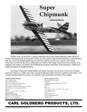
SuperChipmunkInstructionsAnother loop, roll and then a plunge earthward into a dive trailing billowing white clouds ofsmoke. Perilously close to the ground it pulls out and zooms a few hundred feet into a hammerheadstall. No, it isn’t Art Scholl performing at a summer airshow, its the C.G. version of his SuperChipmunk at a R/C fun-fly. We’ve dedicated our model of the Super Chipmunk to the memory of itsdesigner and creator, Art Scholl. His breathtaking precision aerobatics demonstrated to millions thesafety and grace of disciplined flying.Our Super Chipmunk’s super-stable, low speed manners let you fly at a crawl and it simplywon’t quit. Bring it in a little nose high, and you’ll still have solid control to a perfect touch-down. Turnit loose and this performer will put on a airshow with all the flash and flair of the original.Additional Items Needed: 4-5 channel radio CA glue and epoxy .45 to .61 (.90 4-cycle) R/C engine 2-1/4” CGP snap-on spinner Propellers, fuel tank and tubing to suit engine. 14 running feet of covering material Paint One 1-1/4” and two 3-1/4” Wheels Foam rubberOptional Wing Flaps: CG 3/32” Strip Aileron Set CG True 1/16” pushrods 1/8” x 3” x 6” Aircraft PlywoodTools & Supplies NeededMiscellaneous rubber bandsWax paperModeling knife or single edge razor bladeSandpaperPinsDrill sizes:1/16”, 5/64”, 3/32”, 1/8”, 5/32”, 3/16”, & 1/4”Flat building boardPliersSmall ScrewdriversIron for applying coveringMasking tapeCARL GOLDBERG PRODUCTS, LTD. Copyright 1988 Carl Goldberg Products Ltd.
2
3
4
5
ASSEMBLING TOOLSTAIL ASSEMBLYThe stabilizer and fin are sheeted with 1\16” balsa, and theirinterior frames are 3/16” thick balsa. The elevator and rudderare not sheeted, and their frames are 5/16” balsa. for clarity, thestabilizer and fin are built first and then the elevator and rudder.Die- cut beveling tools (from 1/8” ply)1. First, glue narrow strip to handle, keeping themsquare, as shown above left. Then glue wide strip to handleand narrow strip, again keeping things square.1. Make stabilizer (stab) leading edge (LE.) from 3/16” x1/2” balsa sticks. Cut balsa carefully to match with plan atcenter joint and exact length at tips. Pin in position, and glue at center joint. Using die-cut L.E. joiner, center platform, and3/16”x1/2” balsa, glue outline together.2. Cut two strips of 100-200 sandpaper to size shownabove. Tack-cement sandpaper to tools as shown.DIE-CUT SANDING TOOL1. Glue one strip into handles notches keeping them2.square. Then glue remaining strip to other half of handles. Cut one piece of 100-200 grit sandpaper to size of2-1/4”x3”.2. From 1/8” x3/16” strip balsa, cut all trusses to size overplan. Trim well-don’t force into place. Glue in place. Let dry thoroughly.3. Assemble fin in same manner as stab, using die-cut andstick parts. Center 1/4” dowel over grit side of sandpaper. Rollsandpaper around it as shown above left. Slide dowel and sandpaper into tool and hold withrubber band as shown at right. Glue sandpaper to tool.4. The die-cut balsa parts for elevator and rudder must be6
on table.Begin by gluing a 3/16” core between 1/16” top and bottom pieces. In this manner make two elevator tips and twoinner ends as show Center second sheet under stab L.E. and glue in place. Cut out center slot in stab platform for fin post. Laminate rudder pieces in same manner,. Laminate center section.Carefully trim balsa sheet to match stab outline. Turn stab upside down and cover other side in samemanner.5. Assemble elevator halves and rudder in same manner asstab and fin, except use 5/16”x1/2” balsa for L.E. and 1/8”x 5/16” for trusses.6a. Flush edge of 1/16”x3”x24” balsa sheet even with stabT.E. and allow a little extra at tip for trim off. Mark sheet6b. Flush balsa sheet with fin L.E. and glue.width on stab to show gluing limits. Remove sheet and apply CA to T.E., tips and trusses.Turn stab over, position on balsa sheet and press down flat Use stab scrap to complete fin sheeting as shown. Trim sheet to match fin outline.7
7. Place fin and rudder over plan and mark hingelocations. Mark hinge locations for stab and elevator. Position elevator halves and joiner over plan, andcarefully mark elevator L.E.’s for wire joiner location.8. Using CG Center-line marker provided, mark centerlines along edges of parts as shown above. Tilt marker soguide pegs touch the wood, then lightly pass the marker backand forth. Point will scribe center line.12. Using no glue, TEMPORARILY attach elevator to9. At locations marked in Step 7, make a slit wide enoughstab and fin to rudder with hinges in place. Hold partstogether with tape.for the JET Hinge to fit into. IMPORTANT! Although you are installing the hingenow, the hinges are not permanently installed until after themodel is covered. First break corners with the sanding block. Then, followlow with stab sanding tool, rounding off all outside edgesexcept bottom of fin and rudder. Blend stab and elevator at tip. Using a sanding block, flat sand stab, elevator, fin and rudder,smoothing out surfaces.8
13. Remove tapes and separate elevator and rudder fromstab and fin. Tape T.E. of elevator and rudder to work surface, usingappropriate beveling tool, sand L.E. to center-line. Turn partsover and repeat beveling for other side.15. For strength, the elevator joiner areas should be reinforced with nylon fabric as follows. Apply a dab of CA to the elevator and press one endof nylon fabric into it (cover finger with a plastic bag orsimilar).14. Using no glue, trial fit elevator halves together withwire joiner. Carve a radius for better fit at wire bend. Elevatorhalves must lie flat on table and L.E.’s must be aligned. Puncha small pin hole through elevator at rear of joiner hole for gluesqueeze-out. Glue joiner in place. Apply a squiggle of glue to elevator and pull nylonfabric down into it. Rub nylon into the glue with your finger. Continue gluing and apply nylon around elevatorfront and around to other side. Trim nylon Cut. Repeat this procedure and apply nylon on otherjoiner area.This completes the tail assembly construction.9
Wing AssemblyFace ply doublertowards rib 4locationPROCEDURE: The wing panels are assembled bottom side upand then turned over for joining and finishing.IMPORTANT! Although the wing is a symmetrical section,because of internal structure (landing gear and aileron bellcrankmounts), some ribs are not symmetrical(such as Ribs No.2,4,7,&8). As an aid for proper rib orientation, the tip sparnotches for some ribs have only been partially laser cut.IMPORTANT, wing assembly will begin with building a panelovert the “RIGHT WING” on the full-size plan, later on whenit is turned over, this wing will of course become the left wing.“Right” or “Left” wing refers to the panel being assembled during that particular step OVER THE PLANS.Since the wing is built in two halves, and steps 1 to 17 arerepeated in the process, two check boxes are provided witheach of these steps. One for the right wing and one for the left.NotchedendNo notch here2c. Using no glue, place platform ribs 3,9, & 14 on spar at theirrespective places over plan (position rib 3 so ply doubler faces towardsrib 4) Rest notched Trailing Edge (T.E.) on rib platforms(Important: the T.E. has no notch at one end-this unnotched end mustbe at wing center as shown). Press T.E. on rib 3 then slip ribs 9 & 14 into their respective notches,. Pin T.E. to ribs and rib platforms to building board. Glueribs to T.E. and spar (avoid gluing T.E. to rib platforms).Face ply doubler 5 towards rib 41. Position one main spar in place over RIGHT WING (orLEFT WING) on plan. Align spar at center of wing on plan.Hold spar in exact position by crosspinning at circled locationon plan. CAUTION: Do not build two RIGHT WINGS! With landing gear slots facing up, set ribs 4 & 5 in position(NOTE: rib 5 ply doubler must be facing rib 4).2a. Lay parts out as shown. Glue plywood rib doubler 3 Working one at a time, glue remaining ribs 2 to 8 & 10 to 15 toto rib 3 (IMPORTANT! Position slot in ply doubler at top edgeof rib 3).spar and T.E. (NOTE: slots in rib 2 must be towards upper rib edge,slots in ribs 7&8 must face up towards rear of wing as shown). Holdeach rib straight up as it dries. IMPORTANT: for a warp free straightwing, make sure T.E. is kept straight and not bowed up or down, shimwith balsa if required.DOUBLERS MUST FACE EACH OTHER IN WING.2B. Lay parts out as shown. Glue plywood rib doubler 5to rib 5.10
3. Position the Set-Back Gauge (SGB) touching the bottom spar. Touch end of top spar to gauge, and set spar in ribslots. True top spar to all ribs.6b. Align T.E. sheeting with center end of T.E. and adjust sheetso it is flush along T.E. Glue in place. If sheeting edge is not straight,let excess hang out over T.E. for trim off later.6c. Gl ue 3/16”: Sq. x 36” balsa into forward rib notches. Cut tofit around L.G. mount. Balsa should project out from rib 2 about thesame distance as main spar.4. With slot facing out from wing, glue landing gear blockto ribs 3,4,&5.7. An opening for the L.G. mount must be made in the L.E.sheeting. Begin by aligning 5/65”x3”x36” L.E. sheeting with frontedge of spar and flush with spar end. Project and mark two lines straight back from the ends of theL.G. mount and on to the L.E. sheet.5a. Drill four 5/64” dia. holes(1/16” will do) at punchmark locations through aileron bellcrank mounting plates. Slide sheeting over to side of L.G. mount. Align sheet withback of spar and measure and mark the front and rear L.g. block locations. Measure L.G. block locations from the back of the spar.5b. Position aileron mounting plate in rib 7&8 slots, thispart is designed to fit only one way. Glue plate in place.6a. Pin wing at outside of ribs 2 & 15 and T.E. and Cut the opening a little undersize at first and try in place.Enlarge opening as required for proper fit.remove pins from interior area of wing.11
12. Glue laser-cut center sheeting in place, trimming to fit asrequired.8. Tape L.E. sheet in place along back edge of main spar. Withtaped edge acting as a hinge, lift sheeting up and apply glue to tops ofall ribs and both spars. A shot of Kicker on the L.E. sheeting will helpset things quickly. Carefully close sheeting and gently press it downon glued structure beneath. (Moistening the sheeting’s outside surfacecan assist in bending it to air foil shape.) Allow wing structure to dry thoroughly9. Glue laser-cut wing tip sheeting in place.13. Remove all pins from wing structure and turn wing upsidedown. Trim excess T.E. sheeting flush with T.E Position a straight edge along front edge of outer ribs and10. Glue laser-cut tapered L.E. sheet in place.mark a cutting guide line on the overhanging sheeting. Rough trim sheeting overhang to line, leaving about 1/8” ofsheet for final sanding.11. Install Mini-Snaps at both ends of 13-5/8” double threadedwire rod. About 1/16” of threads should protrude through Mini-Snap. Insert Mini-Snaps and rod into wing through rib holes justbehind the spar. Temporarily tape Mini-Snap to aileron mount. Remove platforms from ribs 3,9,& 14.12
Glue second torque block to first, making sure to align slotsand angles. From 1/2”x1/2” triangular balsa, cut reinforcing gussets to fit14. Lay out wing supports as shown. glue together.as shown. Glue together.18. Repeat steps 1 to 17 over “LEFT WING”on plan.15. Using wing cradles, support wing and pin in position over19. With left wing on wing supports, pin in place on plan.plan.16. Lay out laser-cut spar webs as shown. Glue spar webs toPosition RIGHT WING in place next to it. Raise RIGHT WINGfront of top and bottom spars.tip and support it at rib No. 11 using laser-cut gauge. Note; gauge isshaped to fit under curved L.E. and angled T.E. sheeting. Hold gaugefirmly to the rib by tack-cementing or stationery clamps, clothspins,etc.19. Study the entire center joint; all end parts of right wing shouldjust touch those of the left ( tiny gaps are all right). If the fit betweenmost parts is a little loose because one part protrudes too much, slightly sand only the protruding part for better fit. When sanding it is betterto take off too little than too much.13
tapered fit with rib front.22c. Glue block to mounting plate, and lower ribs.20a. Pull wing panels slightly apart and slide aileron servo mountinto forward slot in rib No. 2. FOR FLAPS ONLY. From 1/8” ply (not furnished) cut a flapservo mount using template on wing plan. Position flap mount in rearrib No. 2 slot.20b. Using no glue, temporarily install ply dihedral joiners in leftwing carefully insert them into rib notches. Hold joiners with laser-cutclamps. Reposition right wing next to left, engaging joiners andaileron (and flap) mounts in respective slots in Rib 2. Install joinerclamps on right wing and make a final check of center joint for goodfit of all parts.22d. Position remaining small front rib over block and glue inplace. Remove clamps and separate right wing. Glue joiners to left wing spars, and immediately reinstallclamps. Reposition right wing and pin to hold in position at centerjoint. Glue joiners in place and hold with clamps.23a. Position T.E. sheeting on left wing. Trim sheeting to matchcenter joint. Glue in place.23b. Following same procedure as step 8, install L.E. sheeting onleft wing.23c. Install laser-cut tapered L.E. and center sheeting.24. Repeat step 23 and install top sheeting on right wing.21. Remove narrow strip at bottom of rib No. 1. Position one halfof one front rib No.1 so one side aligns with center line of wing.Adjust rib to align with spar center joints. Glue in place. Glue remaining No.1 rib to first rib, making double thickness rib at center joint.25. Trim and sand balsa L.E. sheeting flush with rib fronts.26. Position Balsa L.E. and hold in place with tape as a hinge.Open and apply CA (Slow dry Thick is good here) to all ribs andsheeting edges. Fold L.E. back into position.22a. Glue dowel mounting plate to front dihedral joiner. Glue small filler rib at center joint.22b. Mark and sand end of 3/4” Sq.x3-5/8” balsa block for14
Fit 1/8” balsa rib 16 inside plastic tip. Slide rib towards tip frontand flush it along all edges. Hold rib in position with a few drops ofCA, then apply more along all seams for permanent bond. Repeat forother tip. Check fit of tips on wing. Using CA, glue tips in place. From 5/64”x3/16” strips of balsa, cut cap strips to cover theexposed edges of all ribs top and bottom. Glue cap strips so they arecentered over each rib.29. Position aileron exit sheeting pieces as shown on plan and gluein place (run aileron pushrods through slots.) From the three 24” ailerons provided, choose the better two forthe ailerons, the remaining one to be cut up for inboard T.E.s (andoptional flaps.)31. For “aileron only” wing cut parts over plan as shown above;30. Position pre-cut opening of wing tips face down on flat sand-two 24” long ailerons , and two 7-9/16” T.E. inboard sections.paper and wipe lightly a few times. Then, run your finger nail alongedges to remove burrs.15
Using a sharp tool, make 1/16” deep grooves in T.E. and ininboard sections. Using threaded end of flap wire, file grooves to arounded shape so half the nylon tubing will lie recessed in both theinboard section and the T.E. For “aileron/flap” wing cut parts as shown: two 19” ailerons,two 9-1/8” flaps, and two 3-1/4” T.E. inboard center sections. Cut overplan for exact size.32. Using the center-line marker, make a center line along entirelength of ailerons, (flaps), and wing T.E.33. FOR AILERON-ONLY WING, continue with this step, for Cut two clearance slots about 5/8” from center joint in wingT.E. and from inner ends of T.E. inboard sections.FLAP wing proceed directly to Step 34. Using no glue at first, temporarily place horns in wing grooves,position both inboard sections and check for horn movement-top tomove about 1” total fore and aft. Glue inboard T.E. in position as shown above. Proceed to Remove T.E. inboard sections, and carefully glue horn wireStep 35.tubing and T.E. inboard sections in place (CAUTION: keep glue offwires).35. Working over Wing Plan, transfer hinge locations shown on34. FOR FLAP WING ONLY, cut nylon tubes to 3” length. slidethe plan to aileron (and flap) and wing T.E. When fitting aileron, keepit centered to allow clearance at ends.nylon tube onto aileron horn wire. Repeat for other tube and wire. Press flap onto end of flap wire to make a mark, with a smallnail, make a hole for the wire. Work carefully, keeping the hole centered inside the flap. Repeat for the other flap. Work carefully so thatwhen finished, the threaded ends of horn wires tilt forward evenly withthe flaps in position on pointed wires. Bend one flap horn as shown above. Hold threaded portion ofwire at about a 45 degree angle. Firmly grasp UNTHREADED end ofwire about 1/2” from end of nylon tube and bend wire horizontally 90degrees. Check on table, adjust as necessary. Make second flap horn opposite to first by bendingUNTHREADED end as shown above.36. Using beveling tool “EA,” bevel front edge of aileron to cen- File bent ends to a slightly pointed shape for easier mounting offlaps later.terline. Turn aileron over and repeat sanding. Repeat for other aileron.16
For flaps, follow this instruction carefully. Lay flaps side byside and upside down as shown. Using sanding tool “RF”, bevel onlythe front bottom edge of flaps up to center line (flaps only have tomove one direction-down.39. Apply a dab of CA to wing and stick one end of 3/4” nylonfabric to it. Let dry until the nylon is glued solidly to the balsa.Flaps “up”Flaps “down” Apply a squiggle of CA to wing and pull nylon fabric downinto it. Rub nylon into glue with your finger (cover finger with plasticbag or similar).37. Fill gaps, joints, etc. with a filler appropriate for balsa. Smoothout with applicator.38. Using 240 grit sandpaper, flat sand entire wing to blend surfacesand remove high spots.17
Temporarily hook-up the aileron servo to the receiver and battery, turn R/C system on and with the transmitter aileron stick and trimtab at neutral, make sure the aileron servo arm is in verticalposition(pointing straight up & down relative to wing). Position servo inside wing on ply mount, carefully align bellcrank pushrods with servo arm. Drill holes as required through plasticmount and screw it to ply mount with #2x3/8” sheet metal screws.4. Enlarge rough wheel opening by lightly tracing the raised outline Mount optional flap servo in same manner behind aileron servowith a sharp knife. Work slowly, making several passed, making thecut deeper each time.as shown on plan.3. Connect Mini-Snaps to opposite ends of servo arm. For balanced5. Glue a pair of half round ply pieces inside pant, on both sides ofaileron movement, check that both aileron bellcranks are parallel to thewing T.E., make adjustments as required to Mini-Snap connections atbellcranks.slot.WHEEL PANTS & LANDING GEAR6. Using a 3/16” dia. drill, open hole on side of pant (do not drillslotted side).1. Rub cut edge of wheel pants over sandpaper and clean burr offedges.7. Using L.G. axle (longer end) into pant. Axle should protrude outpant. Position nylon hold-down over wire at pant side as shown.2. In the bottom of the four pant halves there is a slightly raisedarea, this will be removed for the wheel opening. Cut a rough openingin this area of all four pant halves as shown-but stay about 1/8” infrom raised line.Mark, drill, and mount with a #2x3/8” sheet metal screw. At sideslotted end, use #2 shoulder screw. If L.G. wire fits loose under holddown, remove L.G. and glue scrap plastic shim in slot. To removepant, simply snap hold-down off shoulder screw and rotate it awayfrom L.G. wire.3. The pants are designed so one half fits inside the other. Position Reglue all pant joints using CA. glue.one pant half (with side slot) inside pant half without slot. Adjust partsfor good fit, with about 1/16” to 1/8” overlap. Glue halves togetherwith a few drops of CA around seam.This completes the wheel pants. They can be used as is and simplyapply decals to them later. Or, if desired, the seams can be filled, sanded smooth and the pants painted. Assemble other pant in same manner.18
19
FUSELAGE ASSEMBLY1. Carefully remove all fuselage (fuse) parts from laser-cut sheets.Lightly sand any rough edges.4. Be sure sides are laid down left and right as shown. Temporarily position fuse doublers on fuse side, checking fit andplacement before gluing. Glue fuse doublers in place.2. With side stamped “A” facing out, position two 1/8” ply formers“A” (firewall) together, matching all edges. To hold them in alignment,tape them securely together along one edge as shown at right. Havefour ply clamps ready for next operation.5. Position former doubler “AA” on firewall so that mark at top offirewall is centered in notch in “AA” and match curved edges of parts.3. Open firewalls and apply a liberal amount of glue to one part asshown on left.6. Glue ply former doubler “BB” to bottom of former “B”. Holduntil dry with firewall clamps. From 1/8”x1/2” balsa, cut and glue strips to match formers asshown. Apply strips as shown below. At center-punch mark drill a 1/4” hole through former. Keep edges aligned as you close firewalls and tape oppositeedges together, squeeze firewalls together using laser-cut clamps.When dry, remove clamps and tapes; set clamps aside for use later.20
9. Mount propeller and spinner on your engine. Position engineover fuse top view on plan and compare it to the installation shown.Back of spinner, should protrude about 1/8” beyond the cowl front asshown on the plan. Hold engine in this location. For long 4-cycleengines, check for at least 1/8” clearance between engine rear and firewall; to obtain this clearance the engine may have to be shifted forward as required. Measure the distance from the engine rear to the firewall. Write this measurement down it will be used later for enginemounting.7. Tack-cement the engine between plastic engine bearers, holdingit vertical and parallel to mounts.10. Position one engine mount, butting its rear flange against thefirewall location shown on the plan. Observe how the front enginemounting holes relate to the engine mount. If there is at least 1/4” ofmount forward of this hole location, the spacer plate shown on the planis not needed and you should proceed directly to step 11. If there isdoubt that the mounts do not project far enough for adequate drillingand engine mounting, the spacer must be installed by completing thesteps below. (Note for 4-cycle engines, make sure the spacer does notobstruct the carburetor, cut out spacer center if required for clearance). Position engine/mounts on firewall for side mounted or invertedinstallation. Center-alignment marks are molded into engine mountbases; align these marks directly below the engine mounting flangeswith the corresponding laser-marked line on firewall. Then measureand position mounts so they are equally spaced from second lasermarked line Mark straight down through holes in mounts. Position 1/4”x2-1/8” ply spacer on firewall so that it lies equallyspaced over holes (trace spacer shape on firewall, to check position).Glue spacer in place.8. Drill four 5/32” holes at marked locations.21
Turn firewall over, at hole locations, drill 5/32” holes through1/4” spacer plate.12b. Hold fuse tail ends up, carefully spread fuse rear open, andplug former “E” in place, hold with a rubber band. Working towardsfront, install formers “C” and “D” (balsa doublers facing in towardseach other) in same manner, using rubber bands to hold parts.11. Permanently install four blindnuts in back of firewall usingsocket head screws and washers to pull blindnuts up into the screwholes as shown (firewall with spacer plate shown for clarity). Removescrews after seating blindnuts. Glue blindnut flanges to firewall.12c. With laser-cut separation at tail end facing down, insert topsheet under rubber bands at former “B”, and work it towards tail, slipping it under bands as you go.12a. Place fuse sides one on the other, tape rear together aroundthe back end. Spread fuse fronts apart, and plug former “B”12e. Lock tabs at sides and ends of top sheet into correspondingnotches in fuse sides. Hold parts with tape.12f. Position bottom sheet in same manner, sliding it towards rear.into holes in body sides (doubler “BB” must face forward). Holdparts together with a rubber band.13. Install firewall and pull fuse fronts together with tape as shown.22
From 1/2”x1/2” triangular balsa, cut reinforcing gussets to fitbehind firewall. Glue in place.14. Place fuse over TOP VIEW on plan sheet. Viewing from above,carefully align the fuse to match plan outline. If an area of the fuse isoff, adjust that position in the direction required. Tape parts to hold inposition.17. Set wing in place on fuse, then check and adjust until wing tipsare equidistance from rear end. Project two lines straight forward from fuse sides on wing bottom.15. When satisfied with alignment, permanently glue sides,formers and sheet parts in place. Apply a bead of CA alongall joints inside and outside, or from both sides. Position a 1/8” ply bolt plate about 1/8” away from line and sothat laser-marked line is aligned with T.E. joint as shown. Glue inplace. Repeat for second bolt plate.In the case of formers-it will penetrate the joint and leave a slightreinforcing fillet. Measuring carefully 1-7/16” from wing T.E. and 9/16” in fromfuse sides, drill two holes 5/32” dia. down through wing and boltmounting blocks. Glue two large washers at hole locations. Remove wing from fuse. Install blindnuts in bottom of mounting At tail end, glue bottom sheet to conform to slight bend in fuseblocks, pulling them up in place using screws and washers.sides. Install wing using bolts. Check alignment of wing and fuse atfront. At hole in former “B”, drill a 1/4” dia. hole about 3” deep intowing (try to hold drill square and level into wing).16. Plug 1/8” laser-cut braces into slotted locations in fuse doublers and glue securely in place. Position and glue wing mounting blocks. reglue these joints thoroughly, the wing attaches here-it must be strong. Cut 1/4”x4-1/2” dowel to 3” length. Remove wing and glue thisdowel securely into wing, leaving about 1/4” protruding.23
22. A 1/8” square balsa strip must be glued to the fuselage top toserve as a gluing brace for the top sheeting. Since the front sheeting isthicker than the rear, the front strips are spaced differently than therear as described below.18. With laser-cut separation facing out, bend and position front From 1/8” square balsa strip cut two pieces to fit from bottomnotch in former “TC” to “TE”. Keeping strips about 1/16” in from andparallel to fuse edge, glue to top.bottom sheeting. Glue in place.19. Trial fit the tail wheel bracket at laser-cut separation in bottomsheet. Using a knife or small saw, make a slot for bracket flange asrequired for correct fit. DO NOT GLUE bracket in place at this time! Install remaining 1/8” balsa strip in bottom notches in former“TC” forward to firewall-position this strip 1/8” in from fuse side.23. From 1/4” square balsa cut and glue three top sheeting sup-20a. Cut wing fairings from vac-formed sheets and try fittingports to fit notches in formers “TC”, “TD”, and “TE”.them at L.E. and T.E. Cut out bottom of fairing holes and trim holewalls to match washers. Position fairings for best fit with fuse and glueto wing. Cut three more supports and glue to notches in forward formers“TB”, “TA” and firewall.20b. From scrap 1/8” balsa, glue and trim lower tail end sheeting.24. The three rear sheeting pieces are oversize wedge shapes andare designed to be shifted back and forth for best fit. Begin sheeting installation with one side. Slide sheet in positionso lower edge butts against fuse side and upper edge fits about centeredon 1/4” balsa support. When satisfied with fit, glue sheet in place(slight dampening of outer balsa surface will help curve it to fit fuseshape).21. Install top formers “TA”, “TB”, “TC”, “TD” and “TE” in theirrespective slots in top fuse top (IMPORTANT: tilt formers TB and TCusing gauge “TBTC” as shown below). Install opposite side sheet in same manner. Trim sheets flushwith front of former “TC” and rear of “TE”.24
Slide top center sheet in position and glue in place. Trim to fitwith side sheets.26. Flat sand fuse and round off corners, except the followingareas: top of tail mounting area, and wing saddle-repeat: do not sandthese areas, except very lightly to remove burrs.27. Carefully remove scrap areas from formed cockpit as shownabove. Gently bend cockpit front, rear, and sides along formed seamsdo not bend sharp or plastic will crack.25. Install 1/8” laser-cut front sheeting in dame manner, applyingside pieces first. Where 1/8” balsa butts against former “TC” glue ascrap of 1/8” sq. inside to reinforce the joint. Temporarily place cockpit inside fuse, trimming as required forgood fit. Remove cockpit and set aside for painting.28. Bolt wing in place. Center stab on fuse, measuring to obtain equal distance fromside to side, and from nose of fuse to rear corner of each stab tip. Viewfrom rear to make sure that stab is level in respect to wing. Trial fit fin in place, making sure that it points dead straightahead. When tail parts are aligned and square with fuse, make severalreference marks. Remove fin and stab. Using slow CA or epoxy, glue stab and fin in place. While drying, check parts for square and alignment. Glue balsa filler pieces to fuse at front of stab.25
COWL ASSEMBLY1. Using the measurement from step 9, position and tack-cementengine on mounts (engine must parallel mounts and point straight outfrom firewall). Carefully mark through engine mounting holes to mounts.Remove engine. Drill four
each of these steps. One for the right wing and one for the left. 1. Position one main spar in place over RIGHT WING (or LEFT WING) on plan. Align spar at center of wing on plan. Hold spar in exact position by crosspinning at circled location on plan. CAUTION: Do not build two RIGHT WINGS! 2a. Lay parts out as shown. Glue plywood rib doubler 3