Transcription
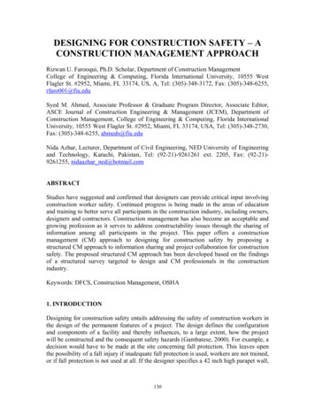
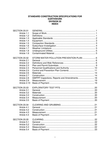
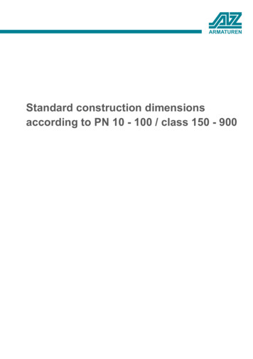
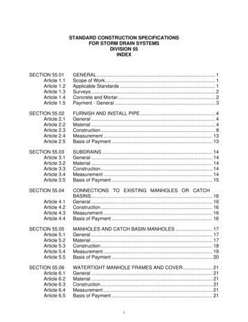
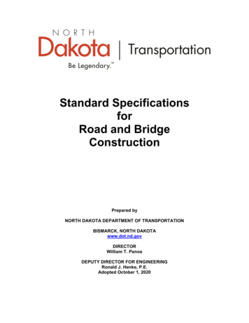
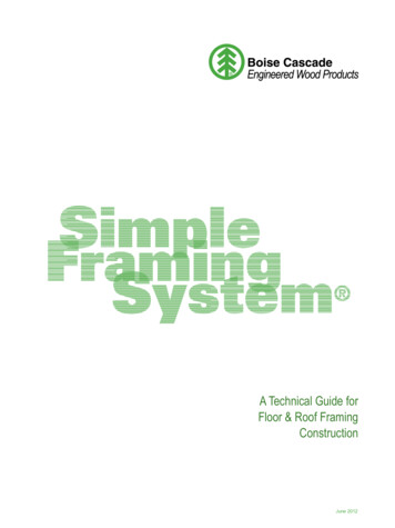
Designation: E1602 – 03 (Reapproved 2010) 1Standard Guide forConstruction of Solid Fuel Burning Masonry Heaters1This standard is issued under the fixed designation E1602; the number immediately following the designation indicates the year oforiginal adoption or, in the case of revision, the year of last revision. A number in parentheses indicates the year of last reapproval. Asuperscript epsilon ( ) indicates an editorial change since the last revision or reapproval. 1 NOTE—Footnote 5 was editorially updated in April 2010.1. Scope1.1 This guide covers the design and construction of solidfuel burning masonry heaters. It provides dimensions for siteconstructed masonry heater components and clearances thathave been derived by experience and found to be consistentwith the safe installation of those masonry heaters.1.2 Values given in SI units are to be regarded as standard.Inch/pound units may be rounded (see IEEE/ASTM SI-10). Alldimensions are nominal unless specifically stated otherwise.All clearances listed in this guide are actual dimensions.1.3 This guide applies to the design and construction ofmasonry heaters built on-site with the components and materials specified herein. It does not apply to the construction/installation requirements for component systems that havebeen safety tested and listed. The requirements for listedmasonry heater systems are specified in the manufacturer’sinstallation instructions.1.4 The design and construction of solid fuel burningmasonry heaters shall comply with applicable building codes.2. Referenced Documents2.1 ASTM Standards:2C11 Terminology Relating to Gypsum and Related BuildingMaterials and SystemsC43 Terminology of Structural Clay Products3C71 Terminology Relating to RefractoriesC270 Specification for Mortar for Unit MasonryC401 Classification of Alumina and Alumina-SilicateCastable RefractoriesE136 Test Method for Behavior of Materials in a VerticalTube Furnace at 750 C1This guide is under the jurisdiction of ASTM Committee E06 on Performanceof Buildings and is the direct responsibility of Subcommittee E06.54 on Solid FuelBurning Appliances.Current edition approved April 1, 2010. Published July 2010. Originallyapproved in 1994. Last previous edition approved in 2003 as E1602 – 03. DOI:10.1520/E1602-03R10.2For referenced ASTM standards, visit the ASTM website, www.astm.org, orcontact ASTM Customer Service at service@astm.org. For Annual Book of ASTMStandards volume information, refer to the standard’s Document Summary page onthe ASTM website.3Withdrawn. The last approved version of this historical standard is referencedon www.astm.org.IEEE/ASTM SI-10 Standard for Use of the InternationalSystem of Units (SI): The Modern Metric System2.2 UL Standards:4UL 103 Chimneys, Factory Built Residential Type andBuilding Heating Appliances3. Terminology3.1 Terms used in this guide are as defined in TerminologyC11, Definitions C43, Terminology C71, and ClassificationC401.3.2 Definitions of Terms Specific to This Standard:3.2.1 approved—acceptable to the authority having jurisdiction.3.2.2 authority having jurisdiction—the organization, office, individual, or agent thereof, who is responsible forapproving construction, materials, equipment, installation, procedure, and so forth. In most cases in which a building permitis required, the authority is typically the building official or hisagent. Where a building permit is not required, the authority istypically the owner or his agent.3.2.3 bypass damper—a valve or plate that provides a directpath to the chimney flue for the flue gases or portion thereof.3.2.4 capping slab—a horizontal refractory barrier coveringthe top of the masonry heater.3.2.5 cleanout opening—an access opening in a flue passageway of the masonry heater or chimney that is designed toallow access to the flue for purposes of inspecting for andremoval of ash, soot, and other extraneous matter that maybecome trapped.3.2.6 damper—an adjustable valve or plate for controllingdraft or the flow of gases, including air.3.2.7 firebox (firechamber)—that portion of the masonryheater that is designed for containing and burning the fuelcharge.3.2.8 gas slot—a small fixed opening that provides a bypassfor unburned flue gases, and is a critical safety feature incertain masonry heater designs (namely those of the Grundofentype with vertical flue runs) (see Fig. 1, Fig. 2, Fig. 3, and Fig.6).4Available from Underwriters Laboratories (UL), 333 Pfingsten Rd., Northbrook, IL 60062-2096, http://www.ul.com.Copyright ASTM International, 100 Barr Harbor Drive, PO Box C700, West Conshohocken, PA 19428-2959, United States.Copyright by ASTM Int'l (all rights reserved); Mon Oct 25 15:06:57 EDT 20101Downloaded/printed byRogerio Teixeira () pursuant to License Agreement. No further reproductions authorized.
E1602 – 03 (2010) 1Copyright by ASTM Int'l (all rights reserved); Mon Oct 25 15:06:57 EDT 20102Downloaded/printed byRogerio Teixeira () pursuant to License Agreement. No further reproductions authorized.
E1602 – 03 (2010) 1Copyright by ASTM Int'l (all rights reserved); Mon Oct 25 15:06:57 EDT 20103Downloaded/printed byRogerio Teixeira () pursuant to License Agreement. No further reproductions authorized.
E1602 – 03 (2010) 13.2.9 hearth extension—the noncombustible surfacing applied to the floor area extending in front of and beyond eachside of the fuel loading door of the masonry heater; also appliesto the floor beneath a masonry heater or beneath an elevatedoverhanging masonry heater hearth.3.2.10 masonry heater base—that portion of the support forthe masonry heater, between the masonry heater and thefoundation, that is below the firebox or the heat exchangeareas.3.2.11 heat-exchange flue channel—a chamber or passageway between the firebox and the chimney flue in which heatresulting directly from combustion of fuel is transferred to thesurrounding masonry.3.2.12 kachel—a European term used to describe a masonryheater tile; a refractory ceramic tile intended for the outer wallof a masonry heater that is designed specifically to store andtransfer heat.3.2.13 listed—equipment or materials included in a listpublished by an organization concerned with product evalua-tion acceptable to the authority having jurisdiction to conductperiodic inspection of production of listed equipment ormaterials and whole listing states either that the equipment ormaterials meet appropriate standards or have been tested andfound suitable for use in a specified manner.3.2.14 masonry heater—a vented heating system of predominantly masonry construction having a mass of at least 800kg (1760 lbs), excluding the chimney and masonry heater base.In particular, a masonry heater is designed specifically tocapture and store a substantial portion of the heat energy froma solid fuel fire in the mass of the masonry heater throughinternal heat exchange flue channels, enable a charge of solidfuel mixed with an adequate amount of air to burn rapidly andmore completely at high temperatures in order to reduceemission of unburned hydrocarbons, and be constructed ofsufficient mass and surface area such that under normaloperating conditions, the external surface temperature of themasonry heater (except in the region immediately surroundingthe fuel loading door(s)), does not exceed 110 C (230 F).Copyright by ASTM Int'l (all rights reserved); Mon Oct 25 15:06:57 EDT 20104Downloaded/printed byRogerio Teixeira () pursuant to License Agreement. No further reproductions authorized.
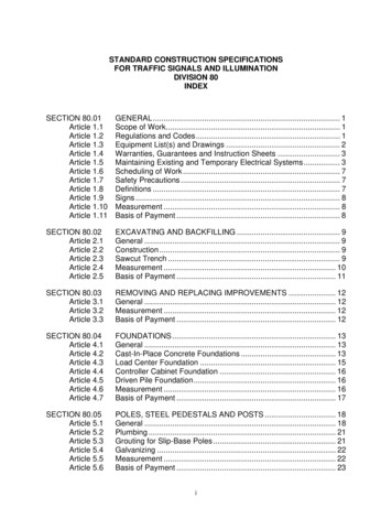
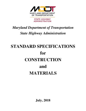
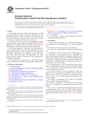
E1602 – 03 (2010) 1NOTE—Clearances form combustible walls or framing may be reduced with an engineered protection system, other than in front of fuel-loading doors.FIG. 4 Clearances to Combustibles(1) 100 mm (4 in.) to combustible framing from masonry heater.(2) 200 mm (8 in.) to ceiling.(3) 200 mm (8 in.) minimum extent of side wall heat shield abovefirebox door.(4) 300 mm (12 in.) hearth extension (sides).(5) 500 mm (20 in.) hearth extension (front).(6) 1200 mm (48 in.) in front of fuel-loading doors to combustibleframing.(7) extent of mandatory heat shield in front of masonry heater; required only when clearance to combustible material from fuel loading door ((8) (9)) is less than 1200 mm (48 in.).(8) 100 mm (4 in.) minimum clearance from side wall of masonryheater to heat shield (if used) or combustible framing.(9) distance from fuel-loading doors to side wall of masonry heater.(7) (8) (9) The sum of these must be greater than or equal to1200 mm (48 in.).3.2.15 mortar, masonry—a mixture of cementitious materials (consisting of Portland or blended cement and hydratedlime, masonry cement, masonry cement and Portland cement,or masonry cement and blended cement), fine aggregate, andsufficient water to produce a workable consistency (see Specification C270).3.2.16 mortar, fire clay—mortar consisting of fine aggregateand fire clay as a binding agent.3.2.17 mortar, soapstone refractory—a mixture of powdered soapstone and sodium silicate.3.2.18 noncombustible material—a material that, in theform in which it is used and under the conditions anticipated,does not ignite, burn, support combustion, or release flammable vapors when subjected to fire or heat. Materials reportedas passing the requirements of Test Method E136 are, for thepurpose of this guide, considered noncombustible.Copyright by ASTM Int'l (all rights reserved); Mon Oct 25 15:06:57 EDT 20105Downloaded/printed byRogerio Teixeira () pursuant to License Agreement. No further reproductions authorized.
E1602 – 03 (2010) 13.2.19 soapstone—a variety of natural stone (hydrated silicaof magnesium) that is suitable for high-temperature applications in masonry heaters.3.2.20 wing wall—a noncombustible lateral projection fromthe exterior wall of a masonry heater for use in bridging thespace between a masonry heater and a combustible partitionwall.4. Significance and Use4.1 This guide can be used by code officials, architects, andother interested parties to evaluate the design and constructionof masonry heaters. It is not restricted to a specific method ofCopyright by ASTM Int'l (all rights reserved); Mon Oct 25 15:06:57 EDT 20106Downloaded/printed byRogerio Teixeira () pursuant to License Agreement. No further reproductions authorized.
E1602 – 03 (2010) 1construction, nor does it provide all specific details of construction of a masonry heater. This guide does provide theprinciples to be followed for the safe construction of masonryheaters.4.2 This guide is not intended as a complete set of directionsfor construction of masonry heaters.4.3 Construction of masonry heaters is complex, and inorder to ensure their safety and performance, construction shallbe done by or under the supervision of a skilled and experienced masonry heater builder.55Organizations that represent a body of knowledge on masonry heater construction and qualified builders include: The Masonry Heater Association of NorthAmerica, 2180 S. Flying Q Lane Tucson, AZ 85731, Richard (Dick) Smith,Executive Director, execdir@mha-net.org or mha.association@yahoo.com (e-mail),520-883-0191 (phone), www.mha-net,org; The Alliance of Masonry Heater andOven Professionals, www.masonryheaters.org, Ken Matesz, Secretary,amhopinc@gmail.com (e-mail); and Masonry Heater Caucus, Hearth, Patio andBarbecue Association, 1901 North Moore Street, Suite 600, Arlington, Va. 22209,703-522-0086 (phone), 703-522-0548 (fax).5. Requirements5.1 Foundation—Masonry heater foundations and foundation walls shall meet local building codes for standard masonryfireplaces and shall be designed with consideration given to themass and size of the masonry heater.5.2 Clearance from Combustibles—Clearances shall be inconformance with this section, as illustrated in Fig. 4.5.2.1 Clearance from Foundation—All combustible structural framing members shall have a clearance of not less than50 mm (2 in.) from the masonry heater foundation.5.2.2 Clearance from Fuel-Loading Door—Maintain aminimum clearance of 1200 mm (48 in.) from combustiblematerials to fuel-loading doors, unless an engineered protection system as specified in 5.2.2.1 is provided, except forclearance directly in front of fuel-loading doors. A minimumclearance of 1200 mm (48 in.) shall be maintained in front offuel-loading doors. This dimension shall not be reduced for anyreason.Copyright by ASTM Int'l (all rights reserved); Mon Oct 25 15:06:57 EDT 20107Downloaded/printed byRogerio Teixeira () pursuant to License Agreement. No further reproductions authorized.
E1602 – 03 (2010) 15.2.2.1 Clearance from fuel-loading doors to combustiblematerials may be reduced, other than in front of fuel-loadingdoors, if the combustible material is protected by an engineeredprotection system acceptable to the authority having jurisdiction. Engineered systems installed for the protection of combustible material shall limit the temperature of the combustiblematerial to 50 C (90 F) above ambient temperature. Systemsshall be designed upon applicable heat transfer principles,taking into account the geometry of the system, the heat losscharacteristics of the structure behind the combustible material,and possible abnormal operating conditions of the masonryheater.5.2.2.1.1 When an engineered protection system is used toreduce the perpendicular clearance from fuel-loading doors, itmust extend a minimum of 200 mm (8 in.) above thefuel-loading doors or firebox opening. In addition, the sum ofthe dimensions from the fuel-loading doors, the distance fromthe heater to combustible material, and the length of theprotection system in front of the heater face shall be no lessthan 1200 mm (48 in.).5.2.3 Clearance from Rear, Side, and Front Walls—Clearance from a masonry heater to combustible structuralframing and other combustible materials shall be not less than100 mm (4 in.), unless an engineered protection system isprovided, or a protection system accepted by the authorityhaving jurisdiction is provided.5.2.3.1 Clearance from a masonry heater to combustiblema
IEEE/ASTM SI-10 Standard for Use of the International System of Units (SI): The Modern Metric System 2.2 UL Standards:4 UL 103 Chimneys, Factory Built Residential Type and Building Heating Appliances 3. Terminology 3.1 Terms used in this guide are as defined in Terminology C11, Definitions C43, Terminology C71, and Classification C401. 3.2 Definitions of Terms Specific to This Standard: 3 .