Transcription
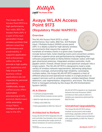
Bulletin 006 May 2022Model RFC Series Residential SprinklersFlat Concealed PendentcULus ListedFeatures cULus Listed as Residential Sprinklers Push-On cover plate installation Low water flow requirementsProduct DescriptionModel RFC Series residential sprinklers are flat cover plate,concealed pendent sprinklers intended for installation inaccordance with NFPA 13, NFPA 13R, or NFPA 13D. Thesprinklers are cULus Listed as Residential Sprinklers inaccordance with UL 199. In addition, Model RFCLL Seriessprinklers are cULus certified for Health Effects to NSF/ANSI/CAN 600, cULus certified less than 0.25% Lead Content toNSF/ANSI 372 Annex G, and Australian WaterMark certified.Model RFC Series sprinklers are offered with either a 165 F(74 C) or 212 F (100 C) temperature rated fusible-linkoperating element. Sprinklers with a 165 F (74 C) temperaturerating are ordinary temperature classification and are listedfor use with a 135 F (57 C) temperature rated cover plate.Sprinklers with a 212 F (100 C) temperature rating areintermediate temperature classification and are listed for usewith a 165 F (74 C) temperature rated cover plate.Model RFC30 & RFC30LLModel RFC43 & RFC43LLModel RFC49 & RFC49LLModel RFC58Model RFC76Model G5 Cover PlateModel RFC Series sprinklers are installed with a Model G5cover plate. Model G5 cover plates are installed by pushing thecover plate into the cup and turning in the clockwise directionuntil it is tight against the ceiling. Model RFC30, RFC30LL,RFC43, RFC43LL, RFC49 and RFC49LL sprinklers allow 1/2”(13 mm) of cover plate adjustment. Model RFC58 and RFC76sprinklers allow 3/4” (19 mm) of cover plate adjustment. ModelG5 cover plates are available in a variety of finishes as listed inTable H.Table ASprinkler ModelNominal K-Factorgpm/psi1/2 (l/min/bar1/2)Max. Coverage Areaft x ft (m x m)Listings &ApprovalsSprinkler IdentificationNumber (SIN)RFC303.0 (43)14 x 14 (4.3 x 4.3)cULusRA0611RFC30LL3.0 (43)14 x 14 (4.3 x 4.3)cULus, LL, WMCSRA3211RFC434.3 (62)20 x 20 (6.1 x 6.1)cULusRA0612RFC43LL4.3 (62)20 x 20 (6.1 x 6.1)cULus, LL, WMCSRA3212RFC494.9 (71)20 x 20 (6.1 x 6.1)cULusRA0616RFC49LL4.9 (71)20 x 20 (6.1 x 6.1)cULus, LL, WMCSRA3216RFC585.8 (84)20 x 20 (6.1 x 6.1)cULusRA0613RFC767.6 (109)20 x 20 (6.1 x 6.1)cULusRA0618cULus: cULus listed for Safety to ANSI/UL199LL:cULus certified for Health Effects to NSF/ANSI/CAN 600cULus certified less than 0.25% Lead Content to NSF/ANSI 372 Annex G.WMCS: Australian WaterMark certified, certificate number 23347.www.reliablesprinkler.com
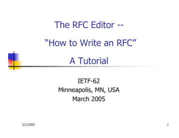
RFC30: SINRA0611RFC30LL: SINRA3211Model RFC30 & RFC30LL Residential SprinklersSensitivityFast-responseTechnical SpecificationsStyle: Flat Concealed PendentThreads: 1/2” NPT or ISO 7-1R1/2Nominal K-Factor: 3.0 (43 metric)Max. Working Pressure: 175 psi (12 bar)Min. Spacing: 8 ft. (2.4 m)Temperature RatingOrdinary:165 F (74 C) sprinkler135 F (57 C) cover plateIntermediate:212 F (100 C) sprinkler165 F (74 C) cover plateMaterial SpecificationsThermal Sensor: Nickel Alloy Solder LinkSprinkler Body: Brass AlloyLevers: Bronze AlloyYoke: Brass AlloySealing Assembly: Nickel Alloy with PTFELoad Screw: Bronze AlloyTowers: Copper AlloyPins: Stainless SteelDeflector: Bronze AlloyCup: SteelCover PlateModel G5 Cover PlateSprinkler WrenchModel FC (without wrench-able cap)Model W3 (with wrench-able cap)Bottom ViewListings and Approvals*cULus Listed to UL 199Cover Plate Finishes(See Table H)*Note: RFC30LL is also cULus certified for Health Effects to NSF/ANSI/CAN 600, cULus certified less than 0.25% Lead Content to NSF/ANSI 372 Annex G,and Australian WaterMark certified (certificate number 23347).Figure 1Model RFC30 & RFC30LL Sprinkler Components and DimensionsTable BModel RFC30 and RFC30LL Sprinkler Hydraulic Design CriteriaMinimum Flow and Residual PressureMax. Coverage Area (2)ft. x ft.(m x m)Ordinary Temperature(1)Intermediate m(l/min)Pressurepsi(bar)12 x 12(3.6 x 3.6)9(34)9.0(0.62)9(34)9.0(0.62)14 x 14(4.3 x 4.3)10(38)11.0(0.76)----Notes:1. For NFPA 13 installations the flow per sprinkler must be the greater of: (1) the flow listed in Table B above and (2) the flow required to achieve a minimumdesign density of 0.1 gpm/sq ft over the design area of the sprinkler.2. For coverage area dimensions less than those listed above, use the minimum required flow for the next larger max. coverage area listed.3. Intermediate temperature listing applies to SIN RA0611 only; not applicable to low-lead version.Bulletin 006May 2022Page 2 of 8www.reliablesprinkler.com
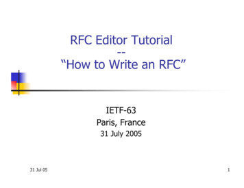
RFC43: SINRA0612RFC43LL: SINRA3212Model RFC43 & RFC43LL Residential SprinklersSensitivityFast-responseTechnical SpecificationsStyle: Flat Concealed PendentThreads: 1/2” NPT or ISO 7-1R1/2Nominal K-Factor: 4.3 (62 metric)Max. Working Pressure: 175 psi (12 bar)Min. Spacing: 8 ft. (2.4 m)Temperature RatingOrdinary:165 F (74 C) sprinkler135 F (57 C) cover plateIntermediate:212 F (100 C) sprinkler165 F (74 C) cover plateMaterial SpecificationsThermal Sensor: Nickel Alloy Solder LinkSprinkler Body: Brass AlloyLevers: Bronze AlloyYoke: Brass AlloySealing Assembly: Nickel Alloy with PTFELoad Screw: Bronze AlloyTowers: Copper AlloyPins: Stainless SteelDeflector: Bronze AlloyCup: SteelCover PlateModel G5 Cover PlateSprinkler WrenchModel FC (without wrench-able cap)Model W3 (with wrench-able cap)Bottom ViewListings and Approvals*cULus Listed to UL 199Cover Plate Finishes(See Table H)*Note: RFC43LL is also cULus certified for Health Effects to NSF/ANSI/CAN 600, cULus certified less than 0.25% Lead Content to NSF/ANSI 372 Annex G,and Australian WaterMark certified (certificate number 23347).Model RFC43 & RFC43LL Sprinkler Components and DimensionsFigure 2Model RFC43 & RFC43LL Sprinkler Hydraulic Design CriteriaMinimum Flow and Residual Pressure (1)Table CMax. Coverage Area (2)ft. x ft.(m x m)Ordinary TemperatureIntermediate /min)Pressurepsi(bar)15 x 15(4.6 x 4.6)12(45)7.8(0.54)12(45)7.8(0.54)16 x 16(4.9 x 4.9)13(49)9.1(0.63)13(49)9.1(0.63)18 x 18(5.5 x 5.5)18(68)17.5(1.21)----20 x 20(6.1 x 6.1)21(79)23.8(1.64)----Notes:1. For NFPA 13 installations the flow per sprinkler must be the greater of: (1) the flow listed in Table C above and (2) the flow required to achieve aminimum design density of 0.1 gpm/sq ft over the design area of the sprinkler.2. For coverage area dimensions less than those listed above, use the minimum required flow for the next larger max. coverage area listed.Bulletin 006May 2022Page 3 of 8www.reliablesprinkler.com
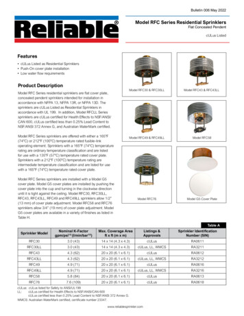
RFC49: SINRA0616RFC49LL: SINRA3216Model RFC49 & RFC49LL Residential SprinklersTechnical SpecificationsStyle: Flat Concealed PendentThreads: 1/2” NPT or ISO 7-1R1/2Nominal K-Factor: 4.9 (71 metric)Max. Working Pressure: 175 psi (12 bar)Min. Spacing: 8 ft. (2.4 m)Material SpecificationsThermal Sensor: Nickel Alloy Solder LinkSprinkler Body: Brass AlloyLevers: Bronze AlloyYoke: Brass AlloySealing Assembly: Nickel Alloy with PTFELoad Screw: Bronze AlloyTowers: Copper AlloyPins: Stainless SteelDeflector: Bronze AlloyCup: SteelCover Plate FinishesSensitivityFast-responseTemperature RatingOrdinary:165 F (74 C) sprinkler135 F (57 C) cover plateIntermediate:212 F (100 C) sprinkler165 F (74 C) cover plateCover PlateModel G5 Cover PlateSprinkler WrenchModel FC (without wrench-able cap)Model W3 (with wrench-able cap)Bottom ViewListings and Approvals*cULus Listed to UL 199(See Table H)*Note: RFC49LL is also cULus certified for Health Effects to NSF/ANSI/CAN 600, cULus certified less than 0.25% Lead Content to NSF/ANSI 372 Annex G,and Australian WaterMark certified (certificate number 23347).Figure 3Model RFC49 & RFC49LL Sprinkler Components and DimensionsTable DModel RFC49 & RFC49LL Sprinkler Hydraulic Design CriteriaMinimum Flow and Residual PressureMax. Coverage Area (2)ft. x ft.(m x m)Ordinary Temperature(1)Intermediate /min)Pressurepsi(bar)16 x 16(4.9 x 4.9)13(49.0)7.0(0.48)13(49.0)7.0(0.48)18 x 18(5.5 x 5.5)17(64.3)12.0(0.83)17(64.3)12.0(0.83)20 x 20(6.1 x 6.1)20(75.7)16.7(1.15)21(79.5)18.4(1.27)Notes:1. For NFPA 13 installations the flow per sprinkler must be the greater of: (1) the flow listed in Table D above and (2) the flow required to achieve a minimum design density of 0.1 gpm/sq ft over the design area of the sprinkler.2. For coverage area dimensions less than those listed above, use the minimum required flow for the next larger max. coverage area listed.Bulletin 006May 2022Page 4 of 8www.reliablesprinkler.com
Model RFC58 Residential SprinklerTechnical SpecificationsStyle: Flat Concealed PendentThreads: 1/2” NPT or ISO 7-1R1/2Nominal K-Factor: 5.8 (84 metric)Max. Working Pressure: 175 psi (12 bar)Min. Spacing: 8 ft. (2.4 m)Material SpecificationsThermal Sensor: Nickel Alloy Solder LinkSprinkler Body: Brass AlloyLevers: Bronze AlloyYoke: Brass AlloySealing Assembly: Nickel Alloy with PTFELoad Screw: Bronze AlloyTowers: Copper AlloyPins: Stainless SteelDeflector: Chrome Plated Bronze AlloyCup: SteelSIN RA0613Cover Plate Finishes(See Table H)SensitivityFast-responseTemperature RatingsOrdinary:165 F (74 C) sprinkler135 F (57 C) cover plateIntermediate:212 F (100 C) sprinkler165 F (74 C) cover plateCover PlateModel G5 Cover PlateSprinkler WrenchModel FC (without wrench-able cap)Model W3 (with wrench-able cap)Bottom ViewListings and ApprovalscULus Listed to UL 199Figure 4Model RFC58 Sprinkler Components and DimensionsTable EModel RFC58 Sprinkler Hydraulic Design CriteriaMinimum Flow and Residual PressureMax. Coverage Areaft. x ft.(m x m)( 1)Flowgpm(l/min)Pressurepsi(bar)16 x 16(4.9 x 4.9)16(60.6)7.6(0.53)18 x 18(5.5 x 5.5)18(68.1)9.6(0.66)20 x 20(6.1 x 6.1)20(75.7)11.9(0.82)(2)Notes:1. For NFPA 13 installations the flow per sprinkler must be the greater of: (1) the flow listed in Table E above and (2) the flow required to achieve aminimum design density of 0.1 gpm/sq ft over the design area of the sprinkler.2. For coverage area dimensions less than those listed above, use the minimum required flow for the next larger max. coverage area listed.Bulletin 006May 2022Page 5 of 8www.reliablesprinkler.com
Model RFC76 Residential SprinklerTechnical SpecificationsStyle: Flat Concealed PendentThreads: 3/4” NPT or ISO 7-1R3/4Nominal K-Factor: 7.6 (109 metric)Max. Working Pressure: 175 psi (12 bar)Min. Spacing: 8 ft. (2.4 m)Material SpecificationsThermal Sensor: Nickel Alloy Solder LinkSprinkler Body: Brass AlloyLevers: Bronze AlloyYoke: Brass AlloySealing Assembly: Nickel Alloy with PTFELoad Screw: Bronze AlloyTowers: Copper AlloyPins: Stainless SteelDeflector: Bronze AlloyCup: SteelSIN RA0618Cover Plate Finishes(See Table H)SensitivityFast-responseTemperature RatingsOrdinary:165 F (74 C) sprinkler135 F (57 C) cover plateIntermediate:212 F (100 C) sprinkler165 F (74 C) cover plateCover PlateModel G5 Cover PlateSprinkler WrenchModel FC (without wrench-able cap)Model W3 (with wrench-able cap)Bottom ViewListings and ApprovalscULus Listed to UL 199Model RFC76 Sprinkler Components and DimensionsFigure 5Model RFC76 Flat Concealed Sprinkler Hydraulic Design CriteriaMinimum Flow and Residual Pressure( 1)Table EMax. Coverage Area (2)ft. x ft.(m x m)Flowgpm(l/min)Pressurepsi(bar)16 x 16(4.9 x 4.9)21(79.5)7.6(0.52)18 x 18(5.5 x 5.5)24(90.8)9.9(0.68)20 x 20(6.1 x 6.1)34(128.7)20(1.4)Notes:1. For NFPA 13 installations the flow per sprinkler must be the greater of: (1) the flow listed in Table E above and (2) the flow required to achieve aminimum design density of 0.1 gpm/sq ft over the design area of the sprinkler.2. For coverage area dimensions less than those listed above, use the minimum required flow for the next larger max. coverage area listed.Bulletin 006May 2022Page 6 of 8www.reliablesprinkler.com
Cover Plate Finishes(1)Table HStandard FinishesSpecial Application FinishesWhite PaintOff White PaintBlack PaintRaw BrassChromeBright BrassFinished BronzeCustom Color Paint(2)Satin ChromeStainless Steel Clad(3)Custom PrintedNotes:1. Paint or any other coating applied over the factory finish will void all approvals and warranties.2. Custom color paint is semi-gloss, unless specified otherwise.3. Stainless steel clad cover plates are Type 316 Stainless Steel on the finished side and C102 Copper Allow on the back side. Cover platesare not listed or approved as corrosion resistant.Installation DimensionsSprinklerModelTable JCoverPlateModelCover PlateDiameterinch (mm)RecommendedHole Diameterin Ceilinginch (mm)Cover PlateAdjustmentinch (mm)Min. toMax. Faceof Fitting toCeiling(1)inch (mm)Min. to Max.Dropped DeflectorDistance belowCeilinginch (mm)Cover 1-1/2 to 2(38 to 51)1/2 to 1(13 to 25)135 F(2)(57 C)or 165 F(3)(74 C)G53-5/16(84)2-5/8(67)3/4(19)1-1/2 to 2-1/4(38 to 57)1/4 to 1(6 to 25)135 F(2) (57 C)or 165 F(3(74 FC76Notes:1. Face of fitting to ceiling dimensions are based on a nominal thread make up. Verify dimensions based on fitting and thread sealing method prior toinstallation. A 1/2” x 1/2” brass nipple extension (Reliable P/N 6999991900) is available where necessary for replacement of existing sprinklers.2. For use with 165 F (74 C) temperature rated sprinklers where the maximum ceiling temperature does not exceed 100 F (38 C).3. For use with 212 F (100 C) temperature rated sprinklers where the maximum ceiling temperature does not exceed 150 F (66 C).InstallationModel RFC series sprinklers are intended to be installed inaccordance with NFPA 13, NFPA 13R, or NFPA 13D, as well asthe requirements of applicable authorities having jurisdiction.Model RFC series sprinklers must not be installed in ceilingswith positive pressure in the space above. Model RFC seriessprinklers are shipped with a wrench-able protective cap thatshould remain on the sprinkler until the sprinkler system is placedin service following construction.Note: When used with gasketed fittings, follow fittingmanufacturer’s installation instructions regarding tightening toachieve a leak-free connection.Model RFC series sprinklers can be installed without removingthe wrench-able protective cap using the Model W3 wrench.Alternatively, Model RFC series sprinklers can be installed usingthe Model FC wrench by temporarily removing the protective capduring installation of the sprinkler. The use of any other wrenchto installed Model RFC series sprinklers is not permitted and maydamage the sprinkler. Fully insert the Model W3 wrench overthe cap until it reaches the bottom of the cup, or the Model FCwrench over the sprinkler until the wrench engages the body.Do not wrench any other part of the sprinkler/cup assembly. TheModel W3 and FC wrenches are designed to be turned with astandard 1/2” square drive. Tighten the sprinkler into the fittingafter applying a PTFE based thread sealant to the sprinkler’sthreads. Recommended installation torque for iron pipe fittings is8 to 18 ft-lbs (11 to 24 N-m) for 1/2” thread sprinklers and 14 to20 ft-lbs (19 to 27 N-m) for 3/4” thread sprinklers.Install the cover plate by hand by pushing the cover plate into thecup and turning the cover in the clockwise direction until it is tightagainst the ceiling.Bulletin 006May 2022Do not exceed the maximum recommended torque. Exceedingthe maximum recommended torque may cause leakage orimpairment of the sprinkler. Use care when inserting or removingthe wrench from the sprinkler to avoid damage to the sprinkler.Page 7 of 8www.reliablesprinkler.com
Installation WrenchesModel FCFor use with Model RFC Series sprinklerswithout wrench-able cap installedService/Spare Head Cabinet WrenchModel W3For use with Model RFC Series sprinklers withwrench-able cap installedListings and ApprovalscULus Listed for Safety to ANSI/UL199Model W8High-strength plastic wrenchfor limited (emergency)use with Model RFC Seriessprinklers without wrench-ablecap installed. Meets NFPArequirements for sprinklerwrench on premises.Additional Listings for RFC30LL, RFC43LL, and RFC49LL: cULus Certified for Health Effects to NSF/ANSI/CAN600 cULus Certified less than 0.25% Lead Content to NSF/ANSI 372 Annex G. Australian WaterMark Certified, certificate number23347.PatentsModel RFC series sprinklers should be inspected and thesprinkler system maintained in accordance with NFPA 25. Donot clean sprinklers with soap and water, ammonia or any othercleaning fluids. Remove dust by gentle vacuuming. Replace anysprinkler cover plate assembly which has been painted (otherthan factory applied) or damaged in any way. A stock of sparesprinklers should be maintained to allow quick replacement ofdamaged or operated sprinklers. Prior to installation, sprinklersshould be maintained in the original cartons and packaging untilused to minimize the potential for damage to sprinklers that wouldcause improper operation or non-operation.GuaranteeFor the Reliable Automatic Sprinkler Co., Inc. guarantee, terms,and conditions, visit www.reliablesprinkler.com.Bulletin 006May 2022Model RFC30, RFC30LL, RFC43 and RFC43LL sprinklers areadditionally covered by U.S. Patent No. 8,776,903.Ordering InformationSpecify the following when ordering.Sprinkler Model (RFC30, RFC30LL, RFC43, RFC43LL,RFC49, RFC49LL, RFC58, RFC76) Temperature RatingCover Plate Model G5 Temperature Rating Finish (See Table H)Sprinkler Wrench Model FC Model W3 Model W8 (Limited use)Page 8 of 8www.reliablesprinkler.comP/N 9999970261MaintenanceModel RFC30, RFC30LL, RFC43, RFC43LL, RFC49, RFC49LL,RFC58, and RFC76 sprinklers are covered by U.S. Patent No.9,248,327 and U.S. Patent No. 7,275,603.
Model RFC30 and RFC30LL Sprinkler Hydraulic Design Criteria Table B Notes: 1. For NFPA 13 installations the flow per sprinkler must be the greater of: (1) the flow listed in Table B above and (2) the flow required to achieve a minimum design density of 0.1 gpm/sq ft over the design area of the sprinkler. 2.