Transcription
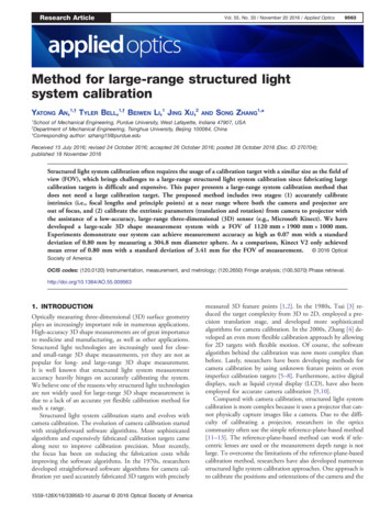
Research ArticleVol. 55, No. 33 / November 20 2016 / Applied Optics9563Method for large-range structured lightsystem calibrationYATONG AN,1,† TYLER BELL,1,† BEIWEN LI,1 JING XU,2ANDSONG ZHANG1,*1School of Mechanical Engineering, Purdue University, West Lafayette, Indiana 47907, USADepartment of Mechanical Engineering, Tsinghua University, Beijing 100084, China*Corresponding author: szhang15@purdue.edu2Received 15 July 2016; revised 24 October 2016; accepted 26 October 2016; posted 28 October 2016 (Doc. ID 270704);published 18 November 2016Structured light system calibration often requires the usage of a calibration target with a similar size as the field ofview (FOV), which brings challenges to a large-range structured light system calibration since fabricating largecalibration targets is difficult and expensive. This paper presents a large-range system calibration method thatdoes not need a large calibration target. The proposed method includes two stages: (1) accurately calibrateintrinsics (i.e., focal lengths and principle points) at a near range where both the camera and projector areout of focus, and (2) calibrate the extrinsic parameters (translation and rotation) from camera to projector withthe assistance of a low-accuracy, large-range three-dimensional (3D) sensor (e.g., Microsoft Kinect). We havedeveloped a large-scale 3D shape measurement system with a FOV of 1120 mm 1900 mm 1000 mm.Experiments demonstrate our system can achieve measurement accuracy as high as 0.07 mm with a standarddeviation of 0.80 mm by measuring a 304.8 mm diameter sphere. As a comparison, Kinect V2 only achievedmean error of 0.80 mm with a standard deviation of 3.41 mm for the FOV of measurement. 2016 OpticalSociety of AmericaOCIS codes: (120.0120) Instrumentation, measurement, and metrology; (120.2650) Fringe analysis; (100.5070) Phase retrieval.http://doi.org/10.1364/AO.55.0095631. INTRODUCTIONOptically measuring three-dimensional (3D) surface geometryplays an increasingly important role in numerous applications.High-accuracy 3D shape measurements are of great importanceto medicine and manufacturing, as well as other applications.Structured light technologies are increasingly used for closeand small-range 3D shape measurements, yet they are not aspopular for long- and large-range 3D shape measurement.It is well known that structured light system measurementaccuracy heavily hinges on accurately calibrating the system.We believe one of the reasons why structured light technologiesare not widely used for large-range 3D shape measurement isdue to a lack of an accurate yet flexible calibration method forsuch a range.Structured light system calibration starts and evolves withcamera calibration. The evolution of camera calibration startedwith straightforward software algorithms. More sophisticatedalgorithms and expensively fabricated calibration targets camealong next to improve calibration precision. Most recently,the focus has been on reducing the fabrication costs whileimproving the software algorithms. In the 1970s, researchersdeveloped straightforward software algorithms for camera calibration yet used accurately fabricated 3D targets with precisely1559-128X/16/339563-10 Journal 2016 Optical Society of Americameasured 3D feature points [1,2]. In the 1980s, Tsai [3] reduced the target complexity from 3D to 2D, employed a precision translation stage, and developed more sophisticatedalgorithms for camera calibration. In the 2000s, Zhang [4] developed an even more flexible calibration approach by allowingfor 2D targets with flexible motion. Of course, the softwarealgorithm behind the calibration was now more complex thanbefore. Lately, researchers have been developing methods forcamera calibration by using unknown feature points or evenimperfect calibration targets [5–8]. Furthermore, active digitaldisplays, such as liquid crystal display (LCD), have also beenemployed for accurate camera calibration [9,10].Compared with camera calibration, structured light systemcalibration is more complex because it uses a projector that cannot physically capture images like a camera. Due to the difficulty of calibrating a projector, researchers in the opticscommunity often use the simple reference-plane-based method[11–13]. The reference-plane-based method can work if telecentric lenses are used or the measurement depth range is notlarge. To overcome the limitations of the reference-plane-basedcalibration method, researchers have also developed numerousstructured light system calibration approaches. One approach isto calibrate the positions and orientations of the camera and the
9564Research ArticleVol. 55, No. 33 / November 20 2016 / Applied Opticsprojector through a complicated and time-consuming calibration process [14–16]. Another approach is to estimate therelationship between the depth and encoded information(e.g., phase) through optimization [17–20].By treating the projector as the inverse of a camera, researchers have developed some similar geometric calibrationapproaches for projector calibration. For example, LegardaSáenz et al. [21] proposed to use phase to establish corresponding points between the projector and the camera and tocalibrate the projector with the calibrated camera parameters;Zhang and Huang [22] developed a method that allows theprojector to capture images like a camera and to calibratecamera and projector independently so the calibration errorof the camera does not affect the projector calibration, andvice versa. Lately, researchers also developed improvedcalibration methods by using linear interpolation [23], bundleadjustment [24], or residual error compensation with planarconstraints [25].All aforementioned camera, projector, and structured lightsystem calibration methods require the use of the calibrationtarget being similar in size to the field of view (FOV) of thedevice; such a typical requirement brings challenges forlarge-range structured light system calibration since preciselyfabricating large calibration targets is often difficult and expensive. Due to this major challenge, structured light technologiesare primarily used in close- and small-range measurementapplications.This paper presents a calibration method that does not require an equivalent size calibration target to the sensing FOVbut rather uses a large-range and low-accuracy 3D sensor inaddition to a regular sized calibration target. Geometric structured light system calibration includes estimating the intrinsics(i.e., focal lengths and principle points) of the camera and theprojector, as well as estimating the extrinsics (i.e., translationand rotation between camera coordinate system and projectorcoordinate system). To our knowledge, the intrinsic parametercalibration is more difficult than extrinsic parameter calibrationsince accurately estimating focal lengths and principle pointsoften requires many feature points within the FOV. In comparison, the extrinsic parameter calibration can use one singlepose and fewer feature points to estimate the transformationfrom one coordinate system to another. The proposed methodtakes advantage of the different difficulty levels of intrinsic andextrinsic calibrations. Specifically, the proposed method isdivided into two stages: the first stage is to accurately calibrateintrinsics at a close range using a more precisely fabricatedcalibration target even though both the camera and projectorare out of focus at this close range, and the second stage is tocalibrate the translation and rotation from camera to projector(i.e., extrinsic parameters) using a low-accuracy, yet large-range,3D sensor (e.g., Microsoft Kinect). The proposed calibrationmethod is built on foundations that we developed for outof-focus camera and projector calibration. In particular, wefound that the severely out-of-focus camera intrinsics can beaccurately estimated directly or by using an active calibrationtarget (e.g., LCD) [26], and the out-of-focus projector can beaccurately calibrated by establishing a one-to-one mapping inthe phase domain and using an in-focus camera to assist infeature point detection [27]. Once the intrinsics are estimated,the extrinsic parameters of the structured light system can beaccurately estimated using a low-resolution and low-accuracy3D sensor with many actively identified feature points ofany object (e.g., a wall). The system we developed for largescale 3D shape measurement can measure a FOV of1120 mm 1900 mm 1000 mm. Experiments demonstrateour system can achieve measurement accuracy as high as0.07 mm with a standard deviation of 0.80 mm by measuringa 304.8 mm diameter sphere. As a comparison, Kinect V2 onlyachieved a mean error of 0.80 mm with a standard deviation of3.41 mm for the FOV of measurement.Section 2 explains the principles of the proposed calibrationmethod. Section 3 presents experimental results to further validate the proposed method. Section 4 discusses the advantagesand possible limitations of the proposed calibration method.Finally, Section 5 summarizes the paper.2. PRINCIPLEThis section thoroughly explains the principles of the proposedlarge-range structured light system calibration method.Specifically, we will present the standard pinhole camera model,phase-shifting algorithm, out-of-focus projector calibration,camera calibration, system extrinsic calibration, and overallframework of large-range structured light system calibration.A. Camera/Projector Lens ModelTo describe the relationship between the 3D world coordinates x w ; yw ; z w and the 2D image coordinates u; v , the mostwidely used model is the pinhole model. Mathematically,the pinhole model for a camera can be represented as2 xw 33" # 2uf u γ u06 yw 7(1)s v 4 0 f v v 0 5 R t 4 w 5;z00 111where s is the scaling factor, f u and f v are the effective focallengths along the u and v directions, γ is the skew factor of the uand v axes, and u0 ; v 0 is the principle point that is the intersecting point between the optical axis and the image plane. Rand t describe the rotation matrix and the translation vectorbetween the world coordinate system and the lens coordinatesystem. Usually, they are represented using the following forms:32" #t1r 11 r 12 r 13t t2 :(2)R 4 r 21 r 22 r 23 5;r 31 r 32 r 33t3Distortion is a very common problem for lenses. Among thedifferent kinds of distortions, radial and tangential distortionsare the two most common. Mathematically, these two kinds ofdistortions can be modeled using the following five parameters:D k1k2p1p2k 3 T ;(3)where k 1 , k2 , and k 3 are radial distortion coefficients, andp1 and p2 are the tangential distortion coefficients. Based onthese coefficients, we can rectify the radial distortion using thefollowing model:
Research ArticleVol. 55, No. 33 / November 20 2016 / Applied Opticsu 0 u 1 k1 r 2 k2 r 4 k3 r 6 ;0v v 1 k 1 r k 2 r k3 r ;246(4)where u; v is the pixel in the input image, u 0 ; v 0 is the pixelcoordinateafter the radialdistortion corrections, ffiffiffiffiffiffiffiffir u u0 2 v v 0 2 . Similarly, we can rectify thetangential distortion using the following model:u 0 u 2p1 uv p2 r 2 2u2 ;v 0 v p1 r 2 2v 2 2p2 uv :(5)The projector has inverse optics from the camera; simplyput, a projector projects an image instead of capturing animage. A projector and a camera share exactly the samemathematical model between their world coordinate systemsand their image coordinate systems. Thus, we can also directlyapply the given pinhole model to describe a projector model.B. Phase-Shifting AlgorithmUsing phase instead of intensity is more advantageous becausephase is more accurate and robust to both noise and ambientlighting effects. There are many phase-shifting methods(three-step, four-step, etc.) and phase unwrapping methods,including spatial and temporal ones. Generally speaking, themore steps are used, the more accurate results we can get.For a number of N equally phase-shifted fringe patterns, mathematically the ith fringe image I i can be described asI i x; y I 0 x; y I 0 0 x; y cos ϕ 2iπ N ;I 0 x; y (6)I 0 0 x; y is the average intensity,is the intensitywheremodulation, i 1; 2; ; N , and ϕ x; y is the phase to besolved for. Using a least square method, we can get PN i 1 P i 1 I sin 2iπ N :(7)ϕ x; y tanNii 1 I cos 2iπ N This equation can give a wrapped phase that ranges from π to π. Next, we must adjust those 2π discontinuities. The process of adjusting 2π discontinuities is called phase unwrapping.Over many years, a variety of phase unwrapping methods havebeen developed. The two most popular categories are spatialunwrapping and temporal unwrapping methods. Essentiallywe want to find a fringe order k x; y for each pixel; thenthe phase can be unwrapped using the following equation:Φ x; y ϕ x; y k x; y 2π:9565Specifically, we will use gray coded patterns for phase unwrapping in later experiments.C. Out-of-Focus Projector Intrinsic CalibrationAs previously mentioned, a projector has inverse optics withrespect to a camera. The most popular way to calibrate a projector is the one proposed by Zhang and Huang [22]. But fora large-range structured light system, fabricating a very largecalibration board at the projector’s focus range and to fit theprojector’s FOV is both difficult and expensive. As in Fig. 1,the projector is focused at the wall, which is a far distance fromthe projector. It is not practical to design that kind of largecalibration board that is the size of a wall. To solve this problem, it is desirable to calibrate the projector within its defocusrange, which is near to the projector.Li et al. [27] prove that out-of-focus projector can be calibrated accurately both theoretically and practically. This givesus the possibility to calibrate the projector of a large-rangestructured light system in its defocused area. As shown inFig. 1, we can use a regular-size calibration board to calibratethe projector at its near defocus range.The whole process of calibrating such an out-of-focus projector is similar to what might be done for a regular small-scalestructured light system. We can use the projector to projectboth horizontal and vertical phase-shifted patterns. Since theprojector is severely defocused at the position of the calibrationboard, we can set the projector to project binary patterns.Because of the effect of defocusing, binary patterns can approximate sinusoidal ones [28]. Next, a camera which is focusedat the calibration board can be used to capture fringe imagesand do phase unwrapping. Theoretically, this can create a oneto-one mapping between a camera pixel and a projector pixelin the phase domain.Take a circle grid calibration board as an example. For aspecific circle center uc ; v c in the camera image, we needto find the corresponding pixel up ; vp in the projector imagecoordinate system. If we project the horizontal patterns ontothe calibration board with the smallest fringe period beingT h , we can compute phase and do phase unwrapping to retrieve the absolute phase ϕcv in the vertical gradient direction.Then for each camera pixel up ; vp , its phase value ϕcv up ; v p maps to a projector pixel line v p by the following linearconstraint:(8)Fundamentally the difference between temporal unwrapping and spatial unwrapping methods is that for the temporalphase unwrapping, one can retrieve an absolute phase map;while spatial methods retrieve a relative phase map. The reasonis that spatial phase unwrapping algorithms usually find k x; y through analyzing the point to be processed and its neighboringpixels. Thus, the obtained phase using a spatial phaseunwrapping method is relative to one point (i.e., a relativephase map). In contrast, temporal phase unwrapping methodsuniquely compute the phase values for each pixel by projectingadditional coded patterns. Thus, the retrieved phase map isan absolute one. An absolute phase is necessary for 3Dreconstruction without ambiguity. Given this, we will use atemporal phase unwrapping method in this research.(u c , v c )CameraCalibration boardWallProjector(u p , v p )Far distanceNear distanceCamera is focused here Camera is defocused hereProjector is defocused here Projector is focused hereFig. 1. Out-of-focus projector calibration. Since fabricating a verylarge calibration board at the projector’s focus range (wall) is bothdifficult and expensive, we instead calibrate the projector at its defocusrange. In the near defocus range, we can use a regular size calibrationboard to calibrate the projector.
9566Research ArticleVol. 55, No. 33 / November 20 2016 / Applied Opticsv p ϕcv uc ; v c T h 2π :(9)Similarly, when we project vertical patterns with the smallestfringe period being T v , we can retrieve the absolute phase ϕch inthe horizontal gradient direction, which maps to an orthogonalprojector pixel line up determined by a similar linear constraintas follows:up ϕch uc ; v c T v 2π :(10)For each circle center pixel uc ; v c in the camera image, wecan find the corresponding pixel up ; v p in the projector image.Using this approach, the projector can see the circle grid patterns. By placing the calibration board in different spatialorientations and finding the circle grid of the projector imagein each pose, finally we can calibrate the projector, similar to acamera, and get its intrinsic matrix.D. Camera Intrinsic CalibrationGiven that the projector is calibrated, it can now be fixed; however, the camera is still in focus at a near distance. So that theentire system can work well for a large sensing range, we nextadjust the camera’s focus and angle with respect to the projector. The camera’s focus is set such that it is now in focus atthe far distance, and its angle from the projector is set to achievean optimal matching between the FOVs of each device.Now that the camera is focused at a far distance, its calibration faces a similar problem as calibrating the projector.Namely, the problem is that using a very large calibration boardto fill the FOV of the camera is not practical in either fabrication or economy. To address this, we take advantage ofthe idea again to calibrate the camera intrinsics at its defocusrange.If the lens used has a short focal length, as in the practicalexperiments, even when the lens is focused at infinity, the levelof camera lens defocusing is still not enough to fail a conventional camera calibration approach. Given this, we can stilldirectly calibrate the camera by capturing different poses ofa calibration board. As in Fig. 2, we can capture different posesof the calibration board at a near distance, albeit the camera isout of focus, and then use the OpenCV calibration toolbox toget the intrinsic matrix of the camera. If a long focal length lensis used, one can adopt the out-of-focus camera calibrationapproach discussed by Bell and Zhang [26]. It uses a digitaldisplay (e.g., LCD monitor) to generate fringe patterns whichencode feature points into the carrier phase; these feature pointscan be accurately recovered even if the fringe patterns are substantially blurred (i.e., the camera is substantially defocused).That method can be adopted here to make our algorithm moregeneric.E. Structured Light System Extrinsic CalibrationIn traditional methods of calibrating the extrinsic parameters ofa structured light system, a regular sized calibration board isused within the FOV of each device. This works well forsmall-range structured light systems, yet the calibration boardwill be too small for the large-range structured light system, asshown in Fig. 3. Since the FOV is too large, it is neither practical nor economically efficient to fabricate a very large calibration board to fill the whole FOV of the structured light system.To deal with this problem, we propose a novel method tocalibrate the extrinsic parameters between the projector and thecamera. Our proposed method uses the assistance of a lowaccuracy, large-range 3D sensor (e.g., Microsoft Kinect V2).As shown in Fig. 4, we use the projector to project some markers (e.g., a circle grid) onto a real 3D scene (like a wall), wherewe obtain up ; v p of markers in our predesigned projector image. Then the camera can capture and detect the position uc ; v c of markers in the camera image. Also, the Kinectcan capture and detect the position uk ; v k of markers inthe Kinect color space. Simultaneously, the Kinect can capturethe depth image and map the 3D coordinates x k ; y k ; z k by itsown built-in function into the color space. From here, we canget the 3D coordinate information of those markers in theKinect’s world space. To summarize, for each marker, we have8 c cposition in the camera image coordinate system u ;v ; up ;v p ;position in the projector image coordinate system: k k k x ;y ;z ; 3Dcoordinates in the Kinect space.Using this information for each feature point, the extrinsiccalibration is converted into a conventional stereo calibrationproblem. We can solve for the translation Tc ; Tp and rotationmatrices Rc ; Rp of the projector and camera using one of themany well developed methods or software frameworks, such asthe StereoCalibration method within OpenCV’s CalibrationToolbox.In general, the 3D scene for extrinsic calibration can besome complex environment, not necessarily a wall or a flat object. As long as we find the correspondence between camerapixel, projector pixel, and 3D coordinates, we can calibratethe extrinsic matrix between the projector and the camera.Further, this method can be extended by using horizontaland vertical phase-shifting patterns to encode feature pointsand establish correspondence. In this approach, we use theregular camera and Kinect to capture those fringe imagesand do phase computation and unwrapping simultaneously.CameraCameraProjectorNear distanceCamera is defocused hereFar distanceCamera is focused hereFig. 2. Camera intrinsic calibration. For a near focused lens, evenwhen the lens is focused at infinity, the level of camera lens defocusingis still not enough to fail a conventional camera calibration approach.Given this, the camera can be calibrated directly by capturing differentposes of a calibration board at its near defocus range.Regular calibration boardSmall scalelarge scaleFig. 3. Extrinsic calibration explanation. For extrinsic calibration inthe small range, usually we can put a regular calibration board in theworking zone (the eventual capture area of the large-range system). Forlarge-range extrinsic calibration, the regular calibration board will betoo small, and it is not practical to fabricate a very large calibrationboard, let alone use it for flexible calibration.
Research ArticleVol. 55, No. 33 / November 20 2016 / Applied Optics(u c , v c )WallCameraProjected patternProjector(u k , v k )( xk , y k , z k )(u p , v p )KinectFig. 4. Extrinsic calibration principle. We project some markersonto a real 3D scene, then we use the camera and Kinect to captureit at the same time. So for each marker, we can get its position in thecamera image coordinate system uc ; v c , its position in the projectorimage coordinate system up ; v p , and its 3D coordinate x k ; y k ; z k inthe Kinect space.We can use phase to find the correspondence of uc ; v c , up ; v p , and the pixels’ 3D information x k ; y k ; z k fromKinect.With the assistance of a low-accuracy, large-range 3D sensor(e.g., Microsoft Kinect), the calibration process becomes muchmore flexible for the calibration of a large-range structured lightsystem.F. Overall Framework of Large-Range StructuredLight System CalibrationHere we summarize the entire framework of our proposedlarge-range calibration method. Briefly speaking, we split thewhole traditional calibration problem into two stages to makeit adaptable to a large-range structured light system. The firststage is the intrinsic calibration process, and the second stage isthe extrinsic calibration process. The overall framework for alarge-range structured light system calibration is shownin Fig. 5.9567large-range system) and the camera be focused at the near distance. Put a calibration board in front of the system at a neardistance. Let the projector project square binary patterns bothhorizontally and vertically, and the camera capture images simultaneously. Then unwrap the phase and find the absolutephase of the feature points on the calibration board. By featurepoint mapping in the phase domain, the projector can see thefeature points (like circle centers). Place the calibration board atdifferent poses and repeat the above process to get the featuremap up ; v p for each pose. Then use some well-developedalgorithms (like the OpenCV calibration toolbox) to computethe intrinsic matrix of the projector.1-B: Camera intrinsic calibration. Now adjust the camerafocus to be at the far distance (the eventual capture area ofthe large-range system). At a near distance, adopt conventionalcalibration methods (e.g., OpenCV camera calibration) to perform out-of-focus camera calibration. If a far focal length lensused, adopt the out-of-focus camera calibration approachdiscussed by Bell and Zhang [26]. Stage 2: Extrinsic calibration. Set the system properly (e.g.,changing the distance and angle between the projector andcamera) for large-range 3D shape measurement. Project somespecific patterns with feature points up ; v p onto a large 3Dscene with the projector. Let the camera and Kinect capturethe patterns directly, getting the pixel position of the featurepoints uc ; v c in the camera image and corresponding 3D coordinates x k ; yk ; z k in the Kinect’s world space. It is worthnoting that alternatively, instead of projecting feature pointsdirectly, one can also project phase-shifted patterns and findthe correspondence between projector, camera, and Kinect images by phase. By repeating this process for different poses, wecan build a correspondence map for each pose and do stereocalibration for the projector and camera to get their extrinsicparameters including rotation matrices and translation vectors. Stage 1: Intrinsic calibration.1-A: Projector intrinsic calibration. Let the projector befocused at the far distance (the eventual capture area of theCameraCalibration boardWallAProjectorIntrinsiccalibrationNear distanceFar distanceCamera is focused hereCamera is defocused hereProjector is defocused here Projector is focused hereB CameraNear distanceCamera is defocused hereExtrinsiccalibrationFar distanceCamera is focused hereCameraProjected patternProjectorKinectFar distanceCamera is focused hereProjector is focused hereFig. 5. Overall framework for large-range structured light systemcalibration. The proposed method includes two stages: (1) accuratelycalibrate intrinsics (i.e., focal lengths, principle points) at a near rangewhere both camera and projector are out of focus, and (2) calibrate theextrinsic parameters (translation and rotation) from camera to projector with the assistance of a low-accuracy, large-range 3D sensor(e.g., Microsoft Kinect).3. EXPERIMENTTo verify the performance of the proposed method, we developed a structured light system that includes a complementarymetal-oxide-semiconductor camera (Model: DMK23UX174)with a 12 mm focal length lens (Model: ComputarM1214-MP2). The resolution of the camera is set to be1600 1200 pixels. The projector is a digital light processingone (Model: DELL M115HD) with a resolution of1280 800 pixels. The auxiliary 3D sensor we used is aKinect V2 with a depth map resolution of 512 424 pixels.The working distance of the Kinect V2 is 0.5 m 4.5 m.We followed the framework proposed in Section 2.F to calibrate the system. Figure 6 shows the system setup for calibrating the intrinsic matrices of the projector and camera. Since theprojector is substantially defocused at the position of the calibration board, we used square binary phase shifting patternswith fringe periods of T h T v 36 pixels to get a reasonablecontrast when calibrating the projector. As shown in Fig. 6(a),the projected patterns have a sharp binary representation at thedistance of the wall, yet a sinusoidal structure at the distanceof the calibration board, due to the defocusing effect of theprojector. Figure 6(b) shows the setup for camera intrinsiccalibration.
9568Research ArticleVol. 55, No. 33 / November 20 2016 / Applied OpticsProjected patternon the wallWall atfar distanceCalibration boardat near distanceWallProjectorProjected patternCalibration g. 6. Out-of-focus projector calibration and camera calibration.(a) System setup for out-of-focus projector calibration. The projectoris focused at a far distance, and the camera is focused at a near distancewhere the calibration board is placed; (b) system setup for theout-of-focus camera calibration. The camera is focused at a far distance, like the wall. To calibrate it, we can just simply put a calibrationboard at a near distance, since the depth of view of the camera is largeenough to see the specific patterns clearly.To calibrate the extrinsic parameters between the cameraand the projector, the additional 3D sensor we used was theKinect V2. We designed the circle grid patterns as markers thatcan be projected by the projector, and they are used to find thecorrespondence between the Kinect 3D points x k ; y k ; z k , thecamera image points uc ; v c , and the projector image points up ; v p , like the setup shown in Fig. 7(a). Figure 7(b) showsan image captured by Kinect in which the RGB image in thecolor space is projected onto the depth image, from which wecan decode the 3D coordinate information for the featurepoints directly.The final large-range structured light system setup is as inFig. 7(a), excluding the Kinect. It consists of one cameraand one projector. The baseline between the proj
Method for large-range structured light system calibration YATONG AN,1,† TYLER BELL,1,† BEIWEN LI,1 JING XU,2 AND SONG ZHANG1,* 1School of Mechanical Engineering, Purdue University, West Lafayette, Indiana 47907, USA 2Department of Mechanical Engineering, Tsinghua University, Beijing 100084, China *Corresponding author: szhang15@purdue.edu Received 15 July 2016; revised 24 October 2016 .