Transcription
Malla Reddy Engineering College(Autonomous)(An Autonomous institution, Autonomy granted by UGC and affiliated to JNTUH, Accredited by NAAC with ‘A’Grade, Accredited by NBA (2008-11) & Recipient of World Bank Assistanceunder TEQIP phase – II S.C.1.1for the period (2011-14))Maisammaguda, Dhulapally (Post. Via. Kompally), Secunderabad – 500 100.LAB MANUALENGINEERING MECHANICSI B. TECH- I SEMESTERSubject Code: 80305Academic Year 2018-19Regulations: MR18NAME:USN:BATCH: SECTION:
2018-19Onwards(MR-18)MALLA REDDY ENGINEERING COLLEGE(Autonomous)Code: 80305B.Tech.I SemesterLTP--3ENGINEERING MECHANICS LABCredits: 1.5Prerequisites: Engineering PhysicsCourse Objectives: Student will be able to learn and understand the various basic conceptand principles of Mechanics like Force & Resultant.List of Experiments1. Triangle law and polygon law of forces apparatus.2. Support reaction for a beam apparatus.3. Coefficient of friction apparatus.4. Flywheel apparatus.5. Moment of disc apparatus.6.Jib Crane7. Equilibrium of non concurrent forces apparatus.8. Universal force table.9. Screw jack apparatus.10. Compound pendulum.11. Worm and worm wheel apparatus.12. Differential wheel and axle apparatus.Course outcome:At the end of the course, students should be able to:CO1Verify law of Force Polygon and law of Moments using ForcePolygon and bell crank lever apparatus and also study ParallelForce apparatus.(Simply supported type).3Bloom’sTaxonomyLevelAnalyzingCO2Determine mechanical advantage, Velocity ratio and efficiency of2AnalyzingCourse OutcomeLevel oflearning
CO3CO4CO5a screw jack.Evaluate co-efficient of friction between trolley (slider) and aninclined plane.Verify the error percentage for the universal force table.Determine the moment of inertia of the fly wheel.3Analyzing32AnalyzingAnalyzing
ConductionRepetitionSubmission ofRecordAverageNote: If the student fails to attend the regular lab, theexperiment has to be completed in the same week. Then themanual/observation and record will be evaluated for 50% ofmaximum marks.IISignature(Faculty)Name of the Manual MarksINDEX PAGE
General Instructions to Students Students are informed to present 5 min before the commencement of lab. Students must enter their name in daily book before entering into lab. Students must leave Foot wares before entering lab. Students must not carry any valuable things inside the lab. Students must inform lab assistant before He/She uses any computer. Do not touch anything with which you are not completely familiar. Carelessness maynot only break the valuable equipment in the lab but may also cause serious injury to you and others in the lab. For any software/hardware/ Electrical failure of computer during working, report itimmediately to your supervisor. Never try to fix the problem yourself because you could further damage the equipment and harm yourself and others in the lab. Students must submit Record book for evaluation before the commencement of lab. Students must keep observation book (if necessary). Students must keep silent near lab premises. Students are informed to follow safety rules. Students must obey lab rules and regulations. Students must maintain discipline in lab. Do not crowd around the computers and run inside the laboratory. Please follow instructions precisely as instructed by your supervisor. Do not start theexperiment unless your setup is verified & approved by your supervisor.
CONTENTSSl. No.Title1. Triangle law and polygon law of forces apparatus.2. Support reaction for a beam apparatus.3. Coefficient of friction apparatus.4. Flywheel apparatus.5. Moment of disc apparatus.6.Jib Crane7. Equilibrium of non concurrent forces apparatus.8. Universal force table.9. Screw jack apparatus.10. Compound pendulum.11. Worm and worm wheel apparatus.12. Differential wheel and axle apparatus.
ENGINEERING MECHANICS LABI SEMScrew Jack ApparatusPage 7 of 67
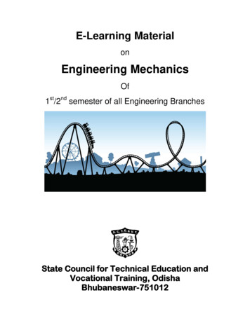
Instruction ManualAim :-To verify the polygon law of forces.Apparatus :-1.Gravesand’s Apparatus,2.Paper Sheet,3.Weight Box,4.Thread,5.Drawing pins & Pencil,6.Mirror Strip Pans.Theory :“Polygon law of apparatus” states that if a number of forces acting on a particle arerepresented in magnitude & direction by sides of a polygon taken in same orde, then theirresultant is represented in magnitude and direction by the closing side of the polygon taken inthe opposite direction.Screw Jack ApparatusPage 8 of 67
PERCENTAGE ERRORS. NO.FORCES( total weights of pans)CALCULATEDRESULTANT T1T – T1 x 1000100Procedure :1.Set the board in a vertical plane & fix the paper sheet with drawing pins2.Pass a thread over two pulleys3.Take a second thread & tie the middle of this thread to the middle of first thread4.Pass the ends of second thread over the other set of two pulleys5.Take a third thread & tie its one end to the point of first two threads6.Attach pans to the free ends of the threads7.Place the weights in the pans in such a manner that the knot comes approximately inthe centre of the paper.8.Mark the line of forces & write down the magnitude of forces9.Remove the paper from the board & produce the line to meet at centre point O10. Select a suitable scale & draw the vector diagram by moving in one direction. draw a bparallel to A B & cut it equal to force P; draw b c parallel to B C & cut it equal to Q;draw c d parallel to C D & cut it equal to force R; draw d e parallel to D E & cut it equalto force S. vector a e will be the resultant force T1 taken in the opposite direction &should be equal to force T which proves the law of polygon forces. If a e is not equal toT then percentage error is found as follows.Observations :-Screw Jack ApparatusPage 9 of 67
PQRST1.2.3.Precautions :1. Pans/weights should not touch the board2. There should be only one central knot on the thread which should be small3. While calculating the total force in each case the weight of the pan should be added tothe weight onto the pan4. Make sure that all pans are at rest when the lines of action of force sare marked5. All the pulleys should be free from frictionI N S T R U C T I O NScrew Jack ApparatusM A N U A LPage 10 of 67
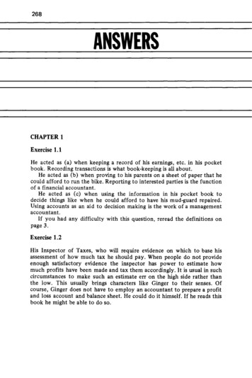
Parts Details1 Wooden Base6 Sliding Hook BracketsExtinction Balance With2 Iron Strip7 Chain3 Upright Bar8 Hanging Chain With Hook4 Cast Aluminum Bracket9 Nut & WasherTie Bar With Compression5 BalanceScrew Jack ApparatusScrew For Fixing The Iron10 StripPage 11 of 67
AIM : To calculate the stresses in various member of the jib craneand find the % age error between the calculated and the observedvalues.Things required :: Jib Crane Apparatus WeightsProcedure ::1. Note the zero error in the compression balance and the springbalance.2. Suspend a wt (w) from the pt. A. Then measure AB,BC, AC, Draw the scale. Note. B is center of thecompression balance and C s vertically above B. Fig.can serve as the vector or stress diagram also because it is atriangle (as any other triangle with sides parallel to it will be asimilar triangle.3. Let w be represented by CB. Then BA will be represent stress inthe Arm AC (Tie). Thus these are the calculated values (Note, we cando without the scale diagram and simple measure AB, AC and BC)4. Note the reading in the compression balance which will give theobserved stress in the Arm AB, and tension in the spring balancegiven the observed force in the Arm AC. Find the %age errorbetween the calculated and observed value.Screw Jack ApparatusPage 12 of 67
5. We have to know whether arms AB and AC are in compression orin tension. Now the pt. A is in equilibrium acted upon by the forcesexerted by arms AB AC and wt (w) as show in FIG 3. Lets firstconsider the nature of the force in the arm AB. The opposite force isexerted by the pt A on the member AB. As the member AB is inequilibrium another opposite force is exerted by the pt Bon themember AB. Thus AB is in compression. Similarly it can be showthat the arm AC is in tension i.e. it is stretched.Screw Jack ApparatusPage 13 of 67
Screw Jack ApparatusPage 14 of 67
I N S T R U C T I O NM A N U A LAIM:To determine the efficiency of a worm and worm wheel apparatusand plot a graph between W & P and W & ŋ.Screw Jack ApparatusPage 15 of 67
WORKING:As the pulley of the worm moves through n revolutions, n teeth ofthe wheel pass completely through the worm. If there are N teeth inthe worm wheel, then N revolutions will have to be given to thepulley of the worm to rotate completely the worm wheel. So that ifthe effort applied at the pulley of the worm moves through Nrevolution the load is raised up by the a distance equal to the lengthof the circumference of the pulley of the worm wheel.So that velocity ratio isN x circumference of pulley of wormCircumference of pulley of worm wheelSINGLE THREADED WORM :Specifications :Starts :SingleLead angle :3 35'Pressure angle : 24 Screw Jack ApparatusPage 16 of 67
Normal Axial Pitch : 8mmPitch of two continuous threads :21.5mmTHEORY :If the worm is single threaded (i.e for onerevolution of the wheel, the worm pushes the wormwheel through one teeth) then for one revolution ofthe effort pulley the distance moved by effort load 2пlThe load drum will move through 1 revolutionTTherefore, distance moved by the load onload drum 2пrTAnd velocity ratio(V.R) distance moved by Pdistance moved by WV.R 2пl lT2пrrTMechanical advantage WPEfficiency,Screw Jack Apparatusŋ M.AV.RPage 17 of 67
PROCEDURE:1. Wrap the string round the pulley of the worm the free end ofwhich is to be tied to the effort.2. Wrap another string to carry the load round the pulley the wormwheel in such a manner that as the effort is applied the load is liftedup.3. Suspend a small weight (w) through the free end of the secondstring and suspend another weight (p) through the free end of thefirst string which should just move the load upward.4. Note w and P, so that mechanical advantage is given by WP5. Increase the load (w) gradually and increase the effort (p)correspondingly and take in this way about seven readings.6. Measure the circumference of the pulley of the worm and alsothat of the worm wheel.7. The percentage efficiency is given by W x 100PV8. Plot a graph between w and p and w and.OBSERVATION:-Screw Jack ApparatusPage 18 of 67
1. Circumference of pulley of the worm (2 R1) 39.25 cm.2. Circumference of pulley of the worm wheel (2 R 2) 43.96 cm.3. No of teeth in the worm wheel (N) 1204. Velocity ratio N x 2πR1 107.142πR2OBSERVATION TABLES. No.1Weight Lifted Effort Applied (P) Mech. Adv. 445300107.1456350107.14% EfficiencyW/PV x 100PRECAUTIONS:Screw Jack ApparatusPage 19 of 67
1. Lubricate the apparatus.2. There should be no overlapping of the strings.3. W should move slowly and in upward direction.4. Effort should be applied carefully on sides of hangers.INSTRUCTION MANUALAim:To determine: The acceleration g of gravity using a compound pendulum. The radius of gyration kG of the compound pendulum about an axis perpendicular to theplane of oscillation and passing through its centre of mass. The moment of inertia IG of the compound pendulum about an axis perpendicular to theplane of oscillation and passing through its centre of mass.Apparatus: Bar Strip Length: 1 mtrBracket Weight (Black colour): 600 gmBar Pendulum Weight: 1.5 kgScrew Jack ApparatusPage 20 of 67
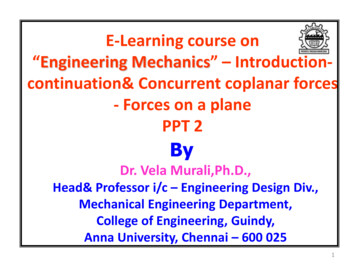
Width: 5 mmThickness: 2.5 cmTheory:In Fig. 1, O is the point of suspension of the compound pendulumand G is its centre of mass; we consider the force of gravity to beacting at G. If h is the distance from O to G, the equation of motionof the compound pendulum isWhere I0is the moment of inertia of the compound pendulum aboutthe point O.Comparing to the equation of motion for a simple pendulumWe see that the two equations of motion are the same if we takeIt is convenient to define the radius of gyration k0 of the compound pendulum such that if all themass Mwere at a distance k0 from O,the moment of inertia about O would be I0, which we do by writing I0 Mk02Substituting this into (1) gives usThe point O′, a distance l from O along a line through G, is called the center of oscillation. Let h′be the distance from G to O′, so thatl h h'. Substituting this into (2), we haveIf IG is the moment of inertia of the compound pendulum about its centre of mass, we can alsodefine the radius of gyration kG about the centre of mass by writing IG MkG2.The parallel axis theorem gives usComparing to (3), we have,If we switch h with h′, equation (4) doesn’t change, so we could have derived it by suspendingthe pendulum from O′. In that case, the center of oscillation would be at O and the equivalentsimple pendulum would have the same length l. Therefore the period would be the same as whensuspended from O. Thus if we know the location of G, by measuring the period T withsuspension at O and at various points along the extended line from O to G, we can find O′ andthus h′.Then using equation (4), we can calculate kG and IG MkG2.Screw Jack ApparatusPage 21 of 67
Knowing h′ gives us l h h′, and since forsmall angle oscillations the periodWe can calculate g usingThe minimum period Tmin , corresponds to theminimum value of l. Recall that l h h′ and that kG2 hh' is a constant, depending only on thephysical characteristics of the pendulum.Thus, l h kG2/h, and the minimum I occurs when,i.e, when h2 kG2, h h' and l 2h 2kG.Thus, at Tmin, l 2kG.Performing the real lab: The compound bar pendulum AB is suspended by passing a knife edge through the firsthole at the end A. The pendulum is pulled aside through a small angle and released,whereupon it oscillates in a vertical plane with a small amplitude. The time for 10oscillations is measured. From this the period T of oscillation of the pendulum isdetermined. In a similar manner, periods of oscillation are determined bysuspending the pendulum through the remaining holes onthe same side of the centre of mass G of the bar. The bar isthen inverted and periods of oscillation are determined bysuspending the pendulum through all the holes on theopposite side of G. The distances d of the top edges ofdifferent holes from the end A of the bar are measured foreach hole.The position of the centre of mass of the bar isfound by balancing the bar horizontally on a knife edge.The mass M of the pendulum is determined by weighingthe bar with an accurate scale or balance. A graph is drawn with the distance d of the various holesfrom the end A along the X-axis and the period T of thependulum at these holes along the Y-axis. The graph hastwo branches, which are symmetrical about G. To determinethe length of the equivalent simple pendulum correspondingScrew Jack ApparatusPage 22 of 67
to any period, a straight line is drawn parallel to the X- axis from a given period T onthe Y- axis, cutting the graph at four points A, B, C, D. The distances AC and BD,determined from the graph, are equal to the corresponding length l. The average length l (AC BD)/2 and l/T2 are calculated. In a similar way , l/T2 is calculated for differentperiods by drawing lines parallel to the X-axis from the corresponding values of T alongthe Y- axis. l/T2 should be constant over all periods T, so the average over all suspensionpoints is taken. Finally, the acceleration due to gravity is calculated from the equation g 4π2(l/T2). Tmin is where the tangent EF to the two branches of the graph crosses the Y-axis. At Tmin,the distance EF l 2kG can be determined, which gives us kG, the radius of gyration ofthe pendulum about its centre of mass, and one more value of g, from g 4π2(2kG/Tmin2) . kG can also be determined as follows. A line is drawn parallel to the Y -axis from thepoint G corresponding to the centre of mass on the X-axis, crossing the line ABCD at P.The distances AP PD AD/2 h and BP PC BC/2 h′ are obtained from thegraph. The radius of gyration kG about the centre of mass of the bar is then determined byequation (4). The average value of kG over the different measured periods T is taken, andthe moment of inertia of the bar about a perpendicular axis through its centre of mass iscalculated using the equation IG MkG2.Performing The Simulation: Suspend the pendulum in the first hole by choosing the length 5 cm on the length slider. Click on the lower end of the pendulum, drag it to one side through a small angle andrelease it. The pendulum will begin to oscillate from side to side. Repeat the process by suspending the pendulum from the remaining holes by choosingthe corresponding lengths on the length slider. Draw a graph by plotting distance d along the X-axis and time period T along the Y-axis.(A spreadsheet like Excel can be very helpful here.) Calculate the average value of l/T2 for the various choices of T, and then calculate g as instep 2 above. Determine kG and IG as outlined in steps 3 and 4 above.Repeat the experiment in different gravitational environments by selecting anenvironment from the drop-down environment menu. If the pendulum has been oscillating,press the Stop button to activate the environment menu.Observations:Screw Jack ApparatusPage 23 of 67
To draw graph:1. To find the value of 'g' :2. To find the radius of gyration and the acceleration of gravity (step 3 above): Radius of gyration about the centre of mass kG EF/2 . Acceleration of gravity, g 4π2(2kG/Tmin2) .3. To find the radius of gyration (step 4 above):Screw Jack ApparatusPage 24 of 67
Results: Average acceleration of gravity, g 4π2(l/T2) . m/s2Average radius of gyration of the pendulum about its centre of mass, kG . mMass of the pendulum M . KgMoment of inertia of the pendulum about its centre of mass, IG MkG2 .Kgm2Screw Jack ApparatusPage 25 of 67
Screw Jack ApparatusPage 26 of 67
INS T R U C T I O NM A N U A LAIM:Determination of Coefficient of friction by the inclinedplane apparatus.Screw Jack ApparatusPage 27 of 67
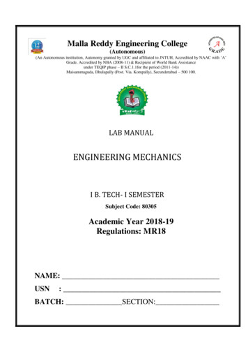
APPARATUS:1. Inclined plane2. Sliding boxes with different surfaces3. String4. Pan5. ThreadTHEORY:When a body slides upon another body, the property by virtue of whichthe motion of one relative to the other is related is called friction. Thefrictional force is directly proportional to the normal reaction ‘N’.F NScrew Jack ApparatusPage 28 of 67
F μNorμ FNSuppose a body of weight W is to be lifted by inclined plane & thisrequires effort P. when this load just move upward a frictional force Facts downward which oppose its motion.Component of load W parallel to the plane W sinComponent of load W perpendicular to the plane W cosConsidering equilibrium parallel to the planeP F W sinF P – W sin (i)Considering equilibrium perpendicular to the planeN W cos .(ii)From (i) & (ii)Co – efficient of friction,Screw Jack ApparatusPage 29 of 67
μ FNMechanical advantage (M.A.) P – W sinW cos WPVelocity ratio (V.R.) distance moved by effortDistance moved by loadLet effort P comes down through one centimeter, movement of the loadalong the plane 1 cmVertical uplift of load 1 x sinV.R. 11 x sin% efficiency M.A.V.R.Screw Jack Apparatus cosecx 100Page 30 of 67
PROCEDURE:-1. Take the inclined plane apparatus & keep it first horizontal andput the slider on it.2. Increase the inclination of inclined board gradually till the sliderjust begins to slide downwards on it.3. Note the angle in this position. This is called angle of repose.4. Place the slider on the plane with the desired angle .5. Tie the slider to the pan with the help of thread passing over thepulley.6. Put the weight in the pan till the slider just start moving. notedown the weight.7. Measure the angle of inclination from the scale provided & findsthe value of μ.8. Calculate M.A., V.R., efficiency.Screw Jack ApparatusPage 31 of 67
OBSERVATIONS:-S.TotalWeight of μ P – W sinNo. weight ofpan W costhe slider weight inW (grams) the panP (grams)M.A. WPV.R. cosec% 9.27150620.241.735.7530.248.9.Screw Jack ApparatusPage 32 of 67
PRECAUTIONS:1. The plane should be clean & smooth.2. The guide pulley should move freely. It should be lubricated tomake it frictionless.3. Weight should be added gently in pan.4. The slider should just begin to move slowly, it should not moveabruptly.5. The direction of thread should be parallel to the inclined plane.Screw Jack ApparatusPage 33 of 67
Screw Jack ApparatusPage 34 of 67
Screw Jack ApparatusPage 35 of 67
MOMENT OF INERTIA OF FLYWHEELAPPARATUSCONTENTS:Page No.AIM02APPRATUS USED02DESCRIPTION03PROCEDURE04MATHEMATICAL CALCULATION05OBSERVATION07PRECAUTIONS08Screw Jack ApparatusPage 36 of 67
I N S T R U C T I O NM A N U A LAIM: - To find the moment of Inertia of a Fly Wheel.APPARATUS USED:Screw Jack ApparatusPage 37 of 67
1. Fly wheel2. Meter scale3. Vernier calipers4. Stop watch5. WeightDESCRIPTION OF APPARATUS:A flywheel is a large heavy wheel, through the center of whichpasses a long cylindrical axle. The center of gravity lies on its axis ofrotation so that when it is mounted over ball bearing, it comes torest any desired position.To increase the moment of inertia, it is usually made thick at therim.To count the number of revolution made by the wheel, a lime ismarked on the circumference. A string is wound on the axle,attached to the peg carries a mass M.THEORY :When a weight is suspended to the free end of a cotton string whichis wrapped round tin: shaft and the other end of which is tied to theshaft and it is allowed to fall to touch the ground then P.E. energypossessed by the falling weight has partly been used to give motionto the fly wheel and partly used in overcoming frictional resistancepresent in the bearings.Screw Jack ApparatusPage 38 of 67
1. Initial Potential Energy (P.E.) Wxh when h is the height of theweight from the level ground.2. Initial Kinetic energy (K.E.) 0. Final P.E 0.3. Final (K.E) ½ (w/g) v 2 ½ I (w2 / g) where ½ (w/g) v2 is the K. Eof the falling wt. And ½ I (w2/g) is the K. E. of the fly wheel andshaft combined and w is the final angular velocity of the wheel or ofthe shaft.4. Work done due to frictional resistance F x h where F isthe force of friction acting tangentially to the shaft.From law of conservation of Energy we can writeW x h ½ (w/g) v2 ½ I (w2 / g) F x h 2g(W - F) x h W v2 I v2 I (W – F) x 2gh - W v2w2But v (final velocity) is given by the formula (u v)/2 h/2 where t isthe time taken for the weight to fall a distance h so that h/t is theaverage velocity.PROCEDURE:1. Attach a mass M (about 500 grams) to one ned of the thinthread and loop is made at the other end which is fastened atthe peg.2. The thread is wrapped evenly round the axle of wheel.3. Allow the mass to descend slowly & count the numberrevolution N1 during descent.Screw Jack ApparatusPage 39 of 67
4. When the thread has unwound itself & detached from the axleafter N1 turns, start the stop watch. Count the numberrevolution before the flywheel comes to rest & stop the stopwatch. Thus N2 are known.5. With the help of vernier calliper,measure the diameter at severalpoint. Thus find R.6. Repeat the experiment with threedifferent masses.7. Calculate the value of I using the given formula.MATHEMATICAL CALCULATIONS :Moment about axis ox,Consider an elementary ring of radius ‘x’ and thickness dxMoment of inertia of this elementary ring about axis OX2 mass x (radius)23 pпx dxTaking mnt of inertia about OX ie integrating the aboveequation2Iox MrScrew Jack ApparatusPage 40 of 67
42By symmetryIoy M (r)4Similarly for axis OZ2M.O.ITaking mnt about OZ mass x (radius)4Ioz pпr22 Mr2OBSERVATIONS:S.n Total loadNo. ofNo. ofMean Times of N2o applied M revolutions of revolutionsN2revolution(k.g.)flywheel before of flywheelT secondsthe massto come todeattachedrest afterN1massdeatachedN21.o.5122.112Screw Jack .23Mean Tsec.1.332.13Page 41 of 67
ote the time accurately to the fraction of a secondNote the value of F when the motion just begins and the flywheel does not move with any acceleration3.Oil the bearings to reduce friction4.Overlapping of the string should be avoided5.Note the time thrice for the same weight (W)Screw Jack ApparatusPage 42 of 67
Screw Jack ApparatusPage 43 of 67
Screw Jack ApparatusPage 44 of 67
MOMENTS DISC APPARATUSCONTENTS:Page AUTIONS07Screw Jack ApparatusPage 45 of 67
I N S T R U C T I O NM A N U A LAIM: To verify the law of moment by rotating disc apparatus.APPARATUS REQUIRED:1. Mirror scale (adjustable)2. Two small pulley (adjustable3. Hollow disc (adjustable)Screw Jack ApparatusPage 46 of 67
4. Four pans5. Slotted weight6. Plumb lineTHEORY & FORMULA USED:The law of moment’s states that if a number of coplanar forces acting on arigid body keep it in equilibrium then the algebric sum of their momentsabout any point in their plan is zero.In the moments disc apparatus, we use the hollow disc, pulleys, threadedpan, mirror scale, plumb line. All these things are adjustable. Due to usethese apparatus make to ensure that the level of fixing threaded pan in ahollow disc should be equal. Requirement of plumb line to adjusting theapparatus at equal level in any positions.The hollow disc & pulleys are moving either clockwise or anti-clockwisedirection. All parts are adjusting on the straight beam which should be rigidlyfixed on the base of the apparatus.Screw Jack ApparatusPage 47 of 67
PROCEDURE:-(1) Put weights in the two pans A and B. such that W1 is the weights inthe pan A plus weight of the pan & W2 weight in the pan B plus weight ofpan B. Note down W1 & W2 .(2) Rotating disc should be placed at a centre point note the thread areshowed at zero on the scale(3) Note down the distance X1 and X2.(4) Now ( W1 x X1 ) will be equal to (W2 x X2 ) that is both the clockwise andanticlockwise and anticlockwise moments will be equal.(5) Take different sets of reading and find out the value of both themoments.Screw Jack ApparatusPage 48 of 67
(6) If both the moment is not equal then find out the percentage errorbetween the clockwise moment and the anti clockwise moment.OBSERVATIONS:-W1 weight in the pan AW2 weight in the pan BX1 distance from the centre point of the apparatus to the end of threadshadow show in the mirror scale of which pan AX2 distance from the centre point of the apparatus to the end of threadshadow show in the mirror scale of which pan BScrew Jack ApparatusPage 49 of 67
S. No. Weight of pan Weight in pan (W1)Weight of pan X1X2Percentage2Weight in pan (W ) (c.m.) 716.60.4PRECAUTIONS:(1) Weights should be placed in the pans A and B gently.(2) Take in to the account the weights of the pan.(3) Lubricate the apparatus.(4) Distance should be noted down carefully.Screw Jack ApparatusPage 50 of 67
Parallel forces ApparatusScrew Jack ApparatusPage 51 of 67
CONTENTS:Page No.AIM03THINGS E05OBSERVATION05PRECAUTIONS06I N S T R U C T I O NScrew Jack ApparatusM A N U A LPage 52 of 67
AIM:To verify the principle of forces in beam of Parallel Forces Apparatus with the help of beamsupported at its ends.Things required:Parallel Forces Apparatus 10 Kg Dial Type, Conical Weights, and Aluminum hangers forhanging weights.Appratus :The apparatus comprising of two dial type weight gauges of 10 kg, one straight wooden beamsof 150cm, a wooden platform for the support of the dial gauges, Two weight hangers forhanging the weights on the wooden beams, Two weights weighing 2 kg aggregate. The beam isprovided with angular slots on them in order to place the hanger in it, the distance betweeneach groove is 5cms. The weight of each hanger will be neglected.The whole apparatus is well designed & painted.Theory:If a system of coplanar forces acting on a rigid body keep it in equilibrium then the algebraicsum of their moments about any point in their plane is zero. Normally a beam is analysed toobtain the maximum stress and this is compared to the material strength to determine thedesign safety margin. It is also normally required to calculate the deflection on the beam underthe maximum expected load. The determination of the maximum stress results from producingthe shear and bending moment diagrams.Screw Jack ApparatusPage 53 of 67
The sign convention used for shear force diagrams and bending moments is only important inthat it should be used consistently throughout a project. The sign convention used on thispage is as below.Nomenclature :e strainσ stress (N/m2)E Young's Modulus σ /e (N/m2)y distance of surface from neutralsurface (m).R Radius of neutral axis (m).I Moment of Inertia (m4 - more normally cm4)Z section modulus I/ymax(m3 - more normally cm3)M Moment (Nm)w Distrubuted load on beam (kg/m) or (N/m as force units)W total load on beam (kg ) or (N as force units)F Concentrated force on beam (N)S Shear Force on Section (N)L length of beam (m)x distance along beam (m)Procedure:1. First of all arrange the apparatus by placing the beams on the given dial gauges asshown in the figure. Note the zero error in the compression balances. When the beamsare supported at it ends.2.Suspend three different weightsfrom the sliding hook against anydivision marked on the beam.3. Note the reaction on the beamgiven by the readings ofcompression balances and takesinto account the zero error fromeach reading.4. Fi
MALLA REDDY ENGINEERING COLLEGE (Autonomous) B.Tech. I Semester Code: 80305 ENGINEERING MECHANICS LAB L T P Credits: 1.5 - - 3 Prerequisites: Engineering Physics Course Objectives: Student will be able to learn and understand the various basic concept and principles of Mechanics like Force & Resultant. List of Experiments 1.