Transcription
E-Learning course on“Engineering Mechanics” – Introductioncontinuation& Concurrent coplanar forces- Forces on a planePPT 2ByDr. Vela Murali,Ph.D.,Head& Professor i/c – Engineering Design Div.,Mechanical Engineering Department,College of Engineering, Guindy,Anna University, Chennai – 600 0251
CONTENTS1. Review of PPT 12. Moment due to the force3. Different types of supports and loads4. Concurrent coplanar forces - Forces on aplaneCourse on “Engineering Mechanics” by Dr. Vela Murali2
Review of PPT 1 Introduction Mechanics and its Classification Difference between Particle and RigidBody based on System of forces Particle Mechanics vs. Rigid Body Mechanicsbased on equilibrium conditionsCourse on “Engineering Mechanics” by Dr. Vela Murali3
Review of PPT 1 Free Body diagram – Its Importancefor solving the problems Various problems – ApplicationsCourse on “Engineering Mechanics” by Dr. Vela Murali4
Review Questions1. What is Mechanics?2. How is it classified?3. Differentiate between Rigid body,deformable body and fluid.4. What is the sequence of the course onEngineering Mechanics (Rigid bodyMechanics)?Course on “Engineering Mechanics” by Dr. Vela Murali5
5. How can you treat a problem as static?6. Differentiate between particlemechanics and Rigid body mechanicsCourse on “Engineering Mechanics” by Dr. Vela Murali6
Rigid body-staticsForces applied on the body externallyat any point on the rigid bodyForce effect and Moment due the forces.Force System containing Non concurrentforces.Course on “Engineering Mechanics” by Dr. Vela Murali7
Conditions for equilibrium in 2DF1F3RxF2F4RyRx , Ry are support reactions F MX 0; FSupport( C )Y 0; 0Course on “Engineering Mechanics” by Dr. Vela Murali8
ExampleThe 2D Rigid body Should satisfythe Equilibrium conditionsRARBAWBl/2l/2 Fy 0; Mabout the point A 0 (or) Mabout the point B 0From which the reactions can be foundCourse on “Engineering Mechanics” by Dr. Vela Murali9
Representation of the Moment in vector formA (x, y, z)Mx y Fz – z FyyMy z Fx – x FzFyorFzzx FxMz x Fy – y FxMo Mx i My j Mz ki jkMo r x F x y zMo Mx2 My2 Mz2Fx Fy FzCourse on “Engineering Mechanics” by Dr. Vela Murali10
Moment about a point on the plane(Equilibrium conditions)F1 Sin ( 1)F1 1 F1 Cos ( 1)F2 Cos ( 2) 2F2F2 Sin ( 2)y1y2Ox1x2Course on “Engineering Mechanics” by Dr. Vela Murali11
Fx 0 F1 Cos ( 1) F2 Cos ( 2) 0 Fy 0 F1 Sin ( 1) - F2 Sin ( 2) 0 Mabout point O (F1 Sin ( 1)) x1 - (F1 Cos ( 1)) y1- (F2 Cos ( 2)) y2 - (F2 Sin ( 2)) x2 0Course on “Engineering Mechanics” by Dr. Vela Murali12
Different types of supportRoller supportFRxFRyNo reaction in„x‟ directionNo reaction in„y‟ directionCourse on “Engineering Mechanics” by Dr. Vela Murali13
FRyNo reaction inthis directionRxHinged support has both„x‟ and „y‟ reactionsCourse on “Engineering Mechanics” by Dr. Vela Murali14
Types of loads(i) Point load – (N)(ii) UDL - (N/m) - Equivalent point load –UDL X length of UDL, which actsat the center of UDL(iii) Moment loadMCourse on “Engineering Mechanics” by Dr. Vela Murali15
(iv) Varying load (N/span)Example:EC50 KN/span3mD 75 KN1m2mArea (1/2) CE x CD (1/2) x 50 x 3 75 KNacts at the centroid of the triangleCourse on “Engineering Mechanics” by Dr. Vela Murali16
problems of Rigid Body subjected toco-planar force system-of differenttypes of loads- with different types ofsupports can be solvedCourse on “Engineering Mechanics” by Dr. Vela Murali17
Concurrent coplanar forces Forces on a planeyF1F20F3xConcurrent co-planar forcesCourse on “Engineering Mechanics” by Dr. Vela Murali18
System of ForcesForces acting on the planeCoplanar forcesForces acting in the spaceNon-Coplanar forcesConcurrent forcesConcurrent forcesNon-concurrent forcesNon-concurrent forcesCollinear forcesParallel forcesParallel forcesNon-Parallel forcesNon-Parallel forcesSystem of ForcesCourse on “Engineering Mechanics” by Dr. Vela Murali19
YY F1F3F1F2F3F2F4X F4X(a) Coplanar-concurrent forceson XY – Plane(b) Coplanar-concurrent forcesin an inclined X Y PlaneCourse on “Engineering Mechanics” by Dr. Vela Murali4
YY F1 F F32F1 F2F3F5F4F5X F4X(c) Coplanar-Non-concurrentforces on XY – Plane(d) Coplanar-Non-concurrentforces in an –X Y PlaneCourse on “Engineering Mechanics” by Dr. Vela Murali21
YY F1F2 F 3F4F4F2F3X F1X(e) Coplanar-collinear forceson XY – Plane(f) Coplanar- collinear forcesin an X Y inclined PlaneCourse on “Engineering Mechanics” by Dr. Vela Murali22
YY F1F2X F1F3F2F3XZ(g) Non-coplanar, concurrent forcesin an XYZ – coordinate systemZ (h) Non-coplanar, concurrentforces in an inclined X Y Z - coordinate systemCourse on “Engineering Mechanics” by Dr. Vela Murali23
YY F4F4F1F2F3F2XZ(i) Non-coplanar, parallel forcesin XYZ–coordinate systemF3X F1Z (j) Non-coplanar, parallel forcesin an inclined X Y Z -coordinateCourse on “Engineering Mechanics” by Dr. Vela Murali24
YF2F2 F3F3F4F1F4F5F1F5XZ(k) Non-coplanar, non-concurrent,non-parallel forces in an XYZ –coordinate system(l) Non-coplanar, non-concurrent,non-parallel forces in an inclinedX Y Z - coordinate systemCourse on “Engineering Mechanics” by Dr. Vela Murali25
Resultant and EquilibrantBF2CFROF1FEAResultant and EquilibrantCourse on “Engineering Mechanics” by Dr. Vela Murali26
Resultant of two forces by parallelogram lawBF2CFRαOAF1Two forces & its resultant represented in a parallelogramCourse on “Engineering Mechanics” by Dr. Vela Murali27
BFRF2ααθOCMF1ADetermination of the resultant by analytical approachFR F1 F2 2 F1 F2 Cos( )22 F2 Sin Tan F FCos 2 1 1Course on “Engineering Mechanics” by Dr. Vela Murali28
Example 1. If the two concurrent coplanarforces F1 and F2 are of 200 N and 100 Nrespectively acts at a point ‘O’ as shown inFig. Find the magnitude and direction of theresultant by using parallelogram law ofanalytical approach.Course on “Engineering Mechanics” by Dr. Vela Murali29
100 N30o200 NSolution: By using parallelogram lawof analytical approach, magnitude ofthe resultantFR F1 F2 2 F1 F2 Cos( )22where F1 200 N, F2 100 Nand 30o.Course on “Engineering Mechanics” by Dr. Vela Murali30
FR 200 2 100 2 2(200)(100) Cos(30) 290.9 NUsing Eq. 2.2for the direction of the resultantF2 Sin F1 F2 Cos Tan 1 100 Sin 30 Tan-1(0.1744) 9.89oTan 1 200 100 Cos 30 F2 100 NFR 290.9 N 30o F1 200 N 9.89oCourse on “Engineering Mechanics” by Dr. Vela Murali31
Example 2. If the two concurrent coplanar forces F1 and F2 act at apoint as shown in Fig. Find the magnitude and direction of theresultant by using parallelogram law of analytical approach.Solution:Course on “Engineering Mechanics” by Dr. Vela Murali32
where F1 1 kN, F2 075 kN and 100o.FR F1 F2 2 F1 F2 Cos( )22FR (1) 2 (0.75)2 2 (1)(0.75) Cos(100) 1.141 kN F2 Sin Tan F1 F2 Cos 1 0.75 Sin 100 40.34oTan 1 0.75 Cos 100 1Resultant force can be represented as 40.34oFR 1.141 kNCourse on “Engineering Mechanics” by Dr. Vela Murali33
Resultant of two forces by triangle law – Graphical approach Finding resultant of two forces by triangle law –graphicalapproachCourse on “Engineering Mechanics” by Dr. Vela Murali34
Resultant of two forces by triangle law – Analytical approachF3F1F2 Sin 1 Sin 2 Sin 3 F1 F2 F3 2 F2 F3 Cos 1 222F2 F1 F3 2 F1 F3 Cos 2 222F3 F1 F2 2 F1 F2 Cos 3 222Course on “Engineering Mechanics” by Dr. Vela Murali35
Example 3. Find the resultant of F1 100 kN and F2 200 kN,which are acting on a particle as shown in Fig. (a) by (i)triangle law using graphical approach (ii) by triangle law ofanalytical approach.Course on “Engineering Mechanics” by Dr. Vela Murali36
Course on “Engineering Mechanics” by Dr. Vela Murali37
Course on “Engineering Mechanics” by Dr. Vela Murali38
R F1 F2 2 F1 F2 Cos 222R 2 100 2 200 2 2 100 200 Cos 135 R 279.79 N and by using sin of triangle rule279.79100200 Sin 135 Sin 1 Sin 2 2 Sin-1(0.5054) 30.36o 1 Sin-1(0.2527) 14.64oResultant ‘R’ 27.79 N60.36oCourse on “Engineering Mechanics” by Dr. Vela Murali39
Resultant of several forces by polygon law – graphical approachF4F2F3F1F2F3F4RF1Given system of concurrentcoplanar forcesForce polygon for the given forcesCourse on “Engineering Mechanics” by Dr. Vela Murali40
Resolution and components of the force along edges of the straightquadrantFF Sin ( ) OForce in I-quadrant, directionaway from the origin & angleknown w.r.to x-axisF Cos ( )Course on “Engineering Mechanics” by Dr. Vela Murali41
FF Cos ( ) OForce in I-quadrant,direction towards the origin& angle known w.r.to y-axisF Sin ( )F Sin ( )F OForce in II-quadrant, directionaway from the origin & angleknown w.r.to x-axisF Cos ( )Course on “Engineering Mechanics” by Dr. Vela Murali42
F Cos ( )F F Sin ( )OForce in II-quadrant, directiontowards the origin & angleknown w.r.to y-axisOF Cos ( ) FF Sin ( )Force in III-quadrant, directionaway from the origin & angleknown w.r.to x-axisCourse on “Engineering Mechanics” by Dr. Vela Murali43
F Sin ( ) FForce in III-quadrant, directiontowards the origin & angleknown w.r.to y-axisF Cos ( )F Cos ( ) FForce in IV-quadrant,direction away from the origin& angle known w.r.to x-axisF Sin ( )Course on “Engineering Mechanics” by Dr. Vela Murali44
F Sin ( ) FForce in IV-quadrant,direction towards the origin& angle known w.r.to y-axisF Cos ( )Course on “Engineering Mechanics” by Dr. Vela Murali45
Finding the resultant of several forces – by Algebraic methodCourse on “Engineering Mechanics” by Dr. Vela Murali46
Course on “Engineering Mechanics” by Dr. Vela Murali47
R F F2x Fy Tan Fx 12y Course on “Engineering Mechanics” by Dr. Vela Murali48
Example 4 Determine the magnitude and the direction of theresultant of a system of concurrent coplanar forcesas shown in Fig.Course on “Engineering Mechanics” by Dr. Vela Murali49
For solution refer the Book on “EngineeringMechanics” By Vela MuraliPublished by Oxford University Press (2010)Page 31, Example 2.6Course on “Engineering Mechanics” by Dr. Vela Murali50
Example 5. Five forces act on a bolt ‘B’ as shown in Fig.Determine the resultant of the forces on the bolt.Course on “Engineering Mechanics” by Dr. Vela Murali51
For solution refer the Book on “EngineeringMechanics” By Vela MuraliPublished by Oxford University Press (2010)Page 41, Example 2.7Course on “Engineering Mechanics” by Dr. Vela Murali52
Resolution and components ofthe force along the edges of theinclined quadrantCourse on “Engineering Mechanics” by Dr. Vela Murali53
W Cos ( ) WW Sin ( )Two sides of the right angle triangle representing thecomponents of the force „W‟ shown in Fig.Course on “Engineering Mechanics” by Dr. Vela Murali54
Resolution of a force in a plane into its components along the edgesof the inclined quadrantF Sin ( )F Cos ( )Course on “Engineering Mechanics” by Dr. Vela Murali55
F Cos ( )F Sin ( )Course on “Engineering Mechanics” by Dr. Vela Murali56
F Sin ( )F Cos ( )Course on “Engineering Mechanics” by Dr. Vela Murali57
F Cos ( )F Sin ( )Course on “Engineering Mechanics” by Dr. Vela Murali58
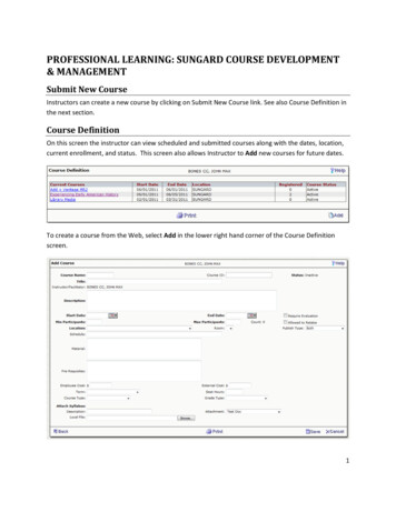
Example 6 Find the magnitudes of the forces F1 and F2as shown in Fig. such that longitudinal and lateral forcesdo not exceeding 200 N and 100 N respectively in a bolt,which is placed 30o to the horizontal.F1F260o30oBolt and nut30o60 NCourse on “Engineering Mechanics” by Dr. Vela Murali59
y’F1 cos30oF1NF2x’30oF1 sin 30o NO30o60 NFree-body diagram and resolving theforces along the x’- and y’-directionsCourse on “Engineering Mechanics” by Dr. Vela Murali60
For solution refer the Book on “EngineeringMechanics” By Vela MuraliPublished by Oxford University Press (2010)Page 48, Example 2.10Course on “Engineering Mechanics” by Dr. Vela Murali61
Equilibrium of a Particle on an Inclined planeFor equilibrium of a particle on an inclined plane,the resultant R 0 Falong the plane 0 and FPerpendicular to the plane 0Example 8Course on “Engineering Mechanics” by Dr. Vela Murali62
30o Falong the plane 0 , (, ve )F Cos(30) – 500 Sin(30) 0F 500 Sin 30 Cos 30 288.7 NApplying second equilibrium equation FPerpendicular to the plane 0, (30o, ve)R- F Sin(30) – 500 Cos(30) 0R 577.4 NCourse on “Engineering Mechanics” by Dr. Vela Murali63
Equilibrium of a Particle by force polygonThree or more concurrent coplanar forces, which areacting on the particle, are such that the particle isbeing under equilibrium.For this condition the force polygon, which is to bedrawn to the scale according to the direction andmagnitude of the system of the forces one after theother and is a closed one.Applicability of Newton’s I – law - EquilibriumCourse on “Engineering Mechanics” by Dr. Vela Murali64
Applicability of equilibrium of a particle –different engineering problems Many of engineering problems are subjected toconcurrent coplanar forces and satisfy the conditions ofstatic equilibriumEither they straight plane problems (or) inclined planeproblems.A free body diagram is to be drawn at a point in thebody, where the lines of actions of the concurrentforces pass through (called as particle) andrepresenting the direction and magnitude of theseforces.Course on “Engineering Mechanics” by Dr. Vela Murali65
Body weight of ‘W’Centroid ofthe bodyCentroid ofthe bodyCWWeight acting on ahorizontal planeWWeight acting on an InclinedplaneCourse on “Engineering Mechanics” by Dr. Vela Murali66
Newton’s III law – Reaction force - EquilibriumW1WWRFig. Reactive force „R‟at the Contact surfaceW1W2R1 W1W2R2 W1 W2Fig. Reactive forces R1 &R2 at two contact surfacesCourse on “Engineering Mechanics” by Dr. Vela Murali67
Reactive force R from an inclined surface due tothe body weightCourse on “Engineering Mechanics” by Dr. Vela Murali68
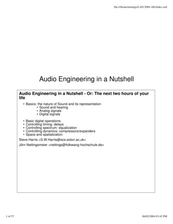
Space diagram and Free Body Diagrams (FBD)AO6O5O2CBO3Cylinders A, B and C have equaldiameter and weight of 16 cmand 100 N respectivelyO4O136 cmsSpace diagram showing the physical conditions of the problemCourse on “Engineering Mechanics” by Dr. Vela Murali69
RB/A45oRB/2BWBRB/1Free Body Diagram (FBD) drawn at point ‘B’Course on “Engineering Mechanics” by Dr. Vela Murali70
A45oRA/C45oRA/BWAFree body diagram drawn at point „A‟Course on “Engineering Mechanics” by Dr. Vela Murali71
RC/A45oCRC/3WCRC/4Free Body Diagram drawn at point „A‟Course on “Engineering Mechanics” by Dr. Vela Murali72
Reference:“EngineeringMechanics”byVela MuraliPublished byOxfordUniversityPress (2010)73
"Engineering Mechanics" -Introduction-continuation& Concurrent coplanar forces - Forces on a plane PPT 2 Dr. Vela Murali,Ph.D., Head& Professor i/c -Engineering Design Div., Mechanical Engineering Department, College of Engineering, Guindy, Anna University, Chennai -600 025 1 By