Transcription
Copyright 2010 Lindau Companies, Inc.April 30, 2010Structural Implications of Mounting SolarPanels on a Residential Wood Structure1
Thank you Andrea Luecke, the City ofMilwaukee, WE Energy, Attendees, andthe US Department of Energy for theopportunity to present this material.Regardless of how one may quantify thebenefits of renewable energies it is ourduty as engineers, installers, and codeofficials to take into account all aspectsof the installation. This includes theimpact on the existing structure.This material should, at the very least, makeone aware of the potential to do harmand instill the need to address thebuilding structure.The following information, calculations,drawings, and conclusions are part of aneducational seminar intended to presenta process. No claim is being made as totheir accuracy or relevance as errorshave been discovered since theircreation. In addition no informationshould be taken from the, drawings,tables or code excerpts due to thepotential for them to be incomplete, out ofdate, or still under development. Consultyour local building official for the currentand complete information.William H. Lindau, P.E.Lindau Companies, Inc.Hudson, Wisconsin715-386-4444Copyright 2010 Lindau Companies, Inc.2
To present the process by which astructural engineer mightevaluate a buildings ability tosupport solar hot water or photovoltaic equipment.Limited to:Residential structures as definedand governed by the UniformDwelling Code of WisconsinAdministrative Code (UDC)To provided examples of drawingsand calculations that could bean important part of thepermitting process.William H. Lindau, P.E.Lindau Companies, Inc.Hudson, Wisconsin715-386-4444Flush mounted flat solar panelsPhoto VoltaicSolar Hot WaterWood ConstructionSimple Trusses or RaftersThe calculations and drawingspresented here have not beenchecked and could contain errors.Copyright 2010 Lindau Companies, Inc.3
Today’s presentation is intended to provide aprocess from which a determination can bemade as to a building’s ability to supportsolar equipment. This process canincorporate many complicated mathematicalcalculations and the designer should beaware of their own, as well as their insurancepolicies, limitations:Copyright 2010 Lindau Companies, Inc.4
Based on my review and conversations with buildingofficials: Calculations may be required by a building official but they donot need to be created by a registered professional engineer. UDC can be interpreted and a permit application submittedby a contractor, designer or owner For all new construction, the Code must be satisfied as aminimum Existing construction that does not meet the minimum oderequirements is not required to be brought within compliancebut no increased or new loads can be imparted on it. Structural elements that do not conform to the Code cannotbe modified in such a way that decrease their strength.Copyright 2010 Lindau Companies, Inc.5
Become familiar with the entire Code – itcan only help l Typically Chapters 20, 21 and theappendices are the most applicable “Work shall be done in a workmanlikemanner” Become familiar with all structureaffected by installation of solarequipment Follow load path through foundation Don’t apply additional loads to nonCode compliant, damaged, orquestionable structural elementswithout providing adequatereinforcementCopyright 2010 Lindau Companies, Inc.6
Uniform Dwelling Code of theWisconsin AdministrativeCode (UDC) Most of the informationneeded is located inChapter 21 andAppendicesCopyright 2010 Lindau Companies, Inc.7
Uniform Dwelling Code of theWisconsin AdministrativeCode (UDC)Copyright 2010 Lindau Companies, Inc.8
Uniform Dwelling Code of theWisconsin AdministrativeCode (UDC) Snow load reduction forroof slope Review all of the Code, itcan only helpCopyright 2010 Lindau Companies, Inc.9
Uniform Dwelling Code of theWisconsin AdministrativeCode (UDC)Copyright 2010 Lindau Companies, Inc.10
Uniform Dwelling Code of theWisconsin AdministrativeCode (UDC) Note limitations of table Snow load reduction11
Uniform Dwelling Code of theWisconsin AdministrativeCode (UDC)How to choose a table:1) Rafter or Floor2) Loads3) Ceiling covering anddeflection requirements4) Roofing weight “Light” roofing 10 psf12
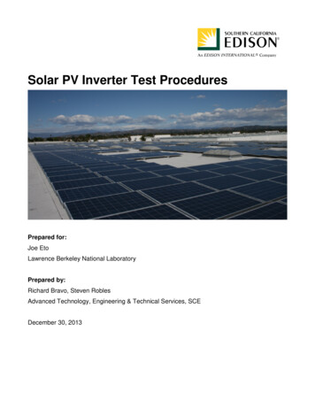
Uniform Dwelling Code of theWisconsin AdministrativeCode (UDC) Use Table R-14 – 30 psf LL 10 psf DL 2 x 6 @ 16” o.c. 10’-0” span Fb 1100 psi E 0.69 x 1,000,000 690,000 psi Locate member size, spacing and span Follow up to Fbmin and down to Emin13
Uniform Dwelling Code of theWisconsin AdministrativeCode (UDC) Note range in values Unless the lumber isstamped with grade andspecies, use SPF (South)and verify No. 2 grade perthe following informationCopyright 2010 Lindau Companies, Inc.14
Simplified method (compare new to existing): Determine original design loads of an existing structure and verify conformance to the currentbuilding code Determine and account for changes to roof loads due to the installation of solar equipment Live loads Snow loads Dead loads Other loads per building code Make comparison between the structure as originally designed and the structure after the solarequipment has been installed.More detailed method of evaluation: Perform complete structural analysis and review of all structural elements affected by theinstallation and make a determination as to their adequacy Includes the analysis of members, their connections, bearing condition, and stability, Follows loads through the foundations Used when the simplified method cannot be performed, is not conclusive, or yields unfavorableresults and reinforcing the structure is not easily accomplished. Removes any doubt of adequacy and grey areas Usually performed by a Structural Engineer.Only the simplified method is included in this presentationCopyright 2010 Lindau Companies, Inc.15
Original building construction documents or as-built drawings noting: Roof construction Rafter size, species, grade, span, and spacing Truss design literature Roof sheathing thickness and type Roofing material and composition Ceiling location and composition Any other elements affected by installation Typical elements include walls, headers, beams, and foundations. Missing or incomplete data requires the designer/reviewer to take a conservative approach andcould delay permitting processSolar equipment specifications and layout including: Weights of all equipment and their distribution Locations of all equipment and supportsCurrent and applicable code and standards Uniform Dwelling Code of the Wisconsin Administrative Code Additional design references as applicableCopyright 2010 Lindau Companies, Inc.16
TRUSSESRAFTERSStructural elements consisting of multiplemembers orientated in triangularpatternsOriginal truss design documents, created bythe manufacturer, are needed to utilizethe simplified method of evaluation.With room within attic space Can be complicated and areoutside the scope of thispresentation.Without room in attic space Simple spans that can beevaluated with the use of UDCtables.Copyright 2010 Lindau Companies, Inc.17
Example 1 – Flush Mounted Solar Hot WaterFlashed Into Roofing – NO RAILS – Rafter RoofExample 2 – Flush Mounted Solar Hot WaterFlashed Into Roof – NO RAILS – Truss RoofExample 3 – Flush Mounted PV SystemSupported by Rails – Rafter RoofExample 4 – Flush Mounted PV SystemSupported by Rails – Truss RoofCopyright 2010 Lindau Companies, Inc.18
1. Check adherence to current building codea.b.c.Tabulate dead loadsDL 10 psf or 10 DL 20 psfCheck UDC tables2. Tabulate new loadsa.b.Solar panel weightRemoval of roofing3. Make comparison & judgment(Creating moment and shear diagrams may be helpful if membercapacity is borderline)Copyright 2010 Lindau Companies, Inc.19
Example 1 – Flush MountedSolar Hot Water Flashed IntoRoofing – NO RAILS – RafterRoof Panels consist of (3) 72”x54”141lb SHW bearing directlyon roof sheathing. Roofing material is removedat panel Panel sits directly on roofsheathing and is supported onall sides Flashing is installed aroundpanelsCopyright 2010 Lindau Companies, Inc.20
Example 1 – Flush MountedSolar Hot Water Flashed IntoRoofing – NO RAILS – RafterRoofCopyright 2010 Lindau Companies, Inc.21
Example 1 – Flush MountedSolar Hot Water Flashed IntoRoofing – NO RAILS – RafterRoof Rafter Zone 2 30 psf No ceiling thus L/180defection requirement “Light” roofing 10 psf Table R-1422
Example 1 – Flush MountedSolar Hot Water Flashed IntoRoofing – NO RAILS – RafterRoof Use Table R-14 – 30 psf LL 10 psf DL 2 x 6 @ 16” o.c. 10’-0” span Fb 1100 psi E 0.69 x 1,000,000 690,000 psi Locate member size, spacing and span Follow up to Fbmin and down to Emin23
Example 1 – Flush MountedSolar Hot Water Flashed IntoRoofing – NO RAILS – RafterRoof Note range in values Unless the lumber isstamped with grade andspecies, use SPF (South)and verify No. 2 grade per“Identifying #2 StructuralFraming” (attached).Copyright 2010 Lindau Companies, Inc.24
Example 1 – Flush MountedSolar Hot Water Flashed IntoRoofing – NO RAILS – RafterRoofOSB) Weights of building materialsshould be calculated for eachjob based on a thoroughexamination of the building Exercise in unit conversionCopyright 2010 Lindau Companies, Inc.25
Example 1 – Flush MountedSolar Hot Water Flashed IntoRoofing – NO RAILS – RafterRoof Always provide manufacturer’sproduct specification thatinclude the product weights withthe permit applicationCopyright 2010 Lindau Companies, Inc.26
Example 1 – Flush MountedSolar Hot Water Flashed IntoRoofing – NO RAILS – RafterRoof As the panel is tilted upward,the lbs/sq ft applied to thehorizontal projection of the roofincreases even though thepanel weight does not changeCopyright 2010 Lindau Companies, Inc.27
Example 1 – Flush MountedSolar Hot Water Flashed IntoRoofing – NO RAILS – RafterRoof Determine area load of system(psf) Area is comprised of systemdimensionsCopyright 2010 Lindau Companies, Inc.28
Example 1 – Flush MountedSolar Hot Water Flashed IntoRoofing – NO RAILS – RafterRoof Already determined the live loadrequirement is satisfied Verify that the dead loads (“DL”)are not in excess of 10 psf If DL 10 psf, further evaluationutilizing shear & momentcalculation is neededCopyright 2010 Lindau Companies, Inc.29
1. Determine original construction design loadsa.b.c.Manufacturer supplied calculationsEngineering analysisOriginal documents2. Tabulate new loadsa.b.PanelsSolar panel weightRemoval of roofing3. Make comparison & judgmentSame process as Example 1Copyright 2010 Lindau Companies, Inc.30
1.2.3.4.Check adequacy of existing rafterDetermine maximum allowable moment and shear (“M” and “V”) ofexisting member based on UDC tables (using span & loads from tables)Determine new load amounts & configuration on each rafterCalculate new moments & shear diagrams and compare to maximumallowable moment and shear.If: Mnew Mallow OKVnew Vallow OKIf not: possibly add more supports or reinforce roofCopyright 2010 Lindau Companies, Inc.31
(s/b 2x8)Copyright 2010 Lindau Companies, Inc.32
Example 3 – FlushMounted PV System onRails – Rafter Roof Many structural designmanuals have beamdiagrams and formulas forvarious static loadingconditions such asMmax (WL2)/8Copyright 2010 Lindau Companies, Inc.33
The rail reactions shown here have beencomputed by the use of analysis softwarebecause the rail is continuous over its supportsand indeterminate to solveCopyright 2010 Lindau Companies, Inc.34
Copyright 2010 Lindau Companies, Inc.35
Copyright 2010 Lindau Companies, Inc.36
Copyright 2010 Lindau Companies, Inc.37
Approximate methodsinclude:a. Dividing the load amongthe tributary areas of itssupportsb. Treating all spans assimple spans and usingsummation of momentsand the summation offorces in the verticaldirection to solve for thereactions A conservative approachshould be taken when usingapproximate methodsCopyright 2010 Lindau Companies, Inc.38
Example 3 – FlushMounted PV System onRails – Rafter RoofSimple Spans: single beamsupported at each end (alsoworks for simple cantilevers withsome challenges) Find RB by summing momentsabout support AFind RA by summing verticalforcesChart shearArea under shear (“V”) curveas one moves from left to rightcreates the moment (“M“)curveThe slope of the Momentcurve at any point representsthe rate of change in shearMoment curve changesdirection where shear curvecrosses axisCopyright 2010 Lindau Companies, Inc.(10.75) 039
Example 3 – FlushMounted PV System onRails – Rafter Roof Compare resulting maximumMoments and Shears to thedesign Moment and Shears.Copyright 2010 Lindau Companies, Inc.40
Example 3 – FlushMounted PV System onRails – Rafter RoofStart the analysis with therafters supporting the mostload and similar memberswith less load and the sameload configuration can beevaluated by comparisonCopyright 2010 Lindau Companies, Inc.41
Example 3 – FlushMounted PV System onRails – Rafter RoofSimple Spans: single beamsupported at each end (alsoworks for simple cantilevers withsome challenges) Find RB by summing momentsabout support AFind RA by summing verticalforcesChart shearArea under shear (“V”) curveas one moves from left to rightcreates the moment (“M“)curveThe slope of the Momentcurve at any point representsthe rate of change in shearMoment curve changesdirection where shear curvecrosses axisCopyright 2010 Lindau Companies, Inc.42
Example 3 – FlushMounted PV System onRails – Rafter RoofSimple Spans: single beamsupported at each end (alsoworks for simple cantilevers withsome challenges) Find RB by summing momentsabout support AFind RA by summing verticalforcesChart shearArea under shear (“V”) curveas one moves from left to rightcreates the moment (“M“)curveThe slope of the Momentcurve at any point representsthe rate of change in shear(V)Moment curve changesdirection where shear curvecrosses axisCopyright 2010 Lindau Companies, Inc.43
Example 3 – FlushMounted PV System onRails – Rafter RoofStart the analysis with therafters supporting the mostload and similar memberswith less load and the sameload configuration can beevaluated by comparison Do not assume thatbecause the membersatisfies the momentcriteria that it will satisfythe shear criteriaCopyright 2010 Lindau Companies, Inc.44
Copyright 2010 Lindau Companies, Inc.45
Copyright 2010 Lindau Companies, Inc.46
Copyright 2010 Lindau Companies, Inc.47
Copyright 2010 Lindau Companies, Inc.48
1. Determine original construction design loads Manufacturer supplied calculationsEngineering analysisOriginal documents2. Calculate rail reactions, load configuration, and tabulate deadloads If rail reactions fall between nodes, determine maximummoment (M) and shear (V) of members directly supporting railsORIf rail reactions fall at nodes, determine reactions at truss nodesaffected3. Make comparison & judgmentCopyright 2010 Lindau Companies, Inc.49
Example 4 – FlushMounted PV System onRails – Truss RoofReview of Trusses: Capacities aredetermined through alengthy process Usually performed by atruss supplierCopyright 2010 Lindau Companies, Inc.50
Example 4 – FlushMounted PV System onRails – Truss RoofDivide top chord into simplespans and use summation ofmoments and summation ofvertical forces to determineM and V Copyright 2010 Lindau Companies, Inc.51
Example 4 – FlushMounted PV System onRails – Truss RoofTrusses are ideally loadedat nodes / panel pointsCopyright 2010 Lindau Companies, Inc.52
Example 4 – FlushMounted PV System onRails – Truss RoofCourtesy of Alan HarperPlan Review Specialist IIICity of MadisonBuilding InspectionReinforcing roof systemgreat simplifies theapproval process53
Example 1 – Flush Mounted Solar Hot WaterFlashed Into Roofing – NO RAILS – Rafter Roof Evenly distributed loads are usually within the dead loadcapacity of the roof systemExample 2 – Flush Mounted Solar Hot WaterFlashed Into Roof – NO RAILS – Truss Roof Evenly distributed loads are usually within the dead load capacity ofthe roof systemExample 3 – Flush Mounted PV SystemSupported by Rails – Rafter Roof Depending on the rail support configuration point loads can easily bein excess of the roofs capacity.Distributing these loads over members at 24” will almost always beacceptableExample 4 – Flush Mounted PV SystemSupported by Rails – Truss Roof Attachment or distribution to truss panel points/nodes may benecessaryCopyright 2010 Lindau Companies, Inc.54
Grading Existing Lumber#2 Structural FramingSource: National Grading Rule forDimension Lumber, “Standard GradingRules for West Coast Lumber No. 17”(2004 edition), West Coast LumberInspection BureauCourtesy of Alan HarperPlan Review Specialist IIICity of MadisonBuilding Inspection55
Grading Existing Lumber#2 Structural FramingSource: National Grading Rule forDimension Lumber, “Standard GradingRules for West Coast Lumber No. 17”(2004 edition), West Coast LumberInspection BureauCourtesy of Alan HarperPlan Review Specialist IIICity of MadisonBuilding Inspection56
Grading Existing Lumber#2 Structural FramingSource: National Grading Rule forDimension Lumber, “Standard GradingRules for West Coast Lumber No. 17”(2004 edition), West Coast LumberInspection BureauCourtesy of Alan HarperPlan Review Specialist IIICity of MadisonBuilding Inspection57
58
Copyright 2010 Lindau Companies, Inc.59
Copyright 2010 Lindau Companies, Inc.60
Copyright 2010 Lindau Companies, Inc.61
Copyright 2010 Lindau Companies, Inc.62
Copyright 2010 Lindau Companies, Inc.63
Copyright 2010 Lindau Companies, Inc.April 30, 2010Structural Implications of Mounting SolarPanels on a Residential Wood Structure64
23 Use Table R-14 -30 psf LL 10 psf DL 2 x 6 @ 16" o.c. 10'-0" span Example 1 -Flush Mounted Solar Hot Water Flashed Into Roofing -NO RAILS -Rafter Roof Locate member size, spacing and span Follow up to Fb min and down to E min